Page 653 of 687

Downloaded from www.Manualslib.com manuals search engine 6F-4 IGNITION SYSTEM (ELECTRONIC IGNITION SYSTEM)
IGNITION SYSTEM DIAGNOSTIC FLOW TABLE
Step Action Yes No
1Was “Engine Diagnostic Flow Table” in Section 6 per-
formed?Go to Step 2. Go to “Engine Diag.
Flow Table” in Section
6.
2Ignition Spark Test
1) Check all spark plugs for condition and type refer-
ring to “Spark Plugs” section.
2) If OK, perform ignition spark test, referring to “Igni-
tion Spark Test” section.
Is spark emitted from all spark plugs?Go to Step 11. Go to Step 3.
3Diagnostic Trouble Code (DTC) Check
Is DTC stored in ECM?Go to applicable DTC
Diag. Flow Table in
Section 6.Go to Step 4.
4Electrical Connection Check
1) Check ignition coil assemblies and high-tension
cords for electrical connection.
Are they connected securely?Go to Step 5. Connect securely.
5High-tension Cords Check
1) Check high-tension cord for resistance referring to
“High-Tension Cords” section.
Is check result satisfactory?Go to Step 6. Replace high-tension
cord(s).
6Ignition Coil Assembly Power Supply and Ground Cir-
cuit Check
1) Check ignition coil assembly power supply and
ground circuits for open and short.
Are circuits in good condition?Go to Step 7. Repair or replace.
7Ignition Coil Assembly Check
1) Check ignition coil for resistance referring to “Igni-
tion Coil Assembly” section.
Is check result satisfactory?Go to Step 8. Replace ignition coil
assembly.
8Crankshaft Position (CKP) Sensor Check
1) Check crankshaft position sensor referring to Step
2 and 6 of “DTC P0335 (No.23) CKP Sensor Cir-
cuit Malfunction” in Section 6.
Is check result satisfactory?Go to Step 9. Tighten CKP sensor
bolt, replace CKP sen-
sor or CKP sensor
plate.
9Ignition Trigger Signal Circuit Check
1) Check ignition trigger signal wire for open, short
and poor connection.
Is circuit in good condition?Go to Step 10. Repair or replace.
10A Known-good Ignition Coil Assembly Substitution
1) Substitute a known-good ignition coil assembly
and then repeat Step 2.
Is check result of Step 2 satisfactory?Go to Step 11. Substitute a known-
good ECM and then
repeat Step 2.
11Ignition Timing Check
1) Check initial ignition timing and ignition timing
advance referring to “Ignition Timing” section.
Is check result satisfactory?System is in good con-
dition.Check CKP sensor,
CKP sensor plate and
input signals related to
this system.
Page 657 of 687

Downloaded from www.Manualslib.com manuals search engine 6F-8 IGNITION SYSTEM (ELECTRONIC IGNITION SYSTEM)
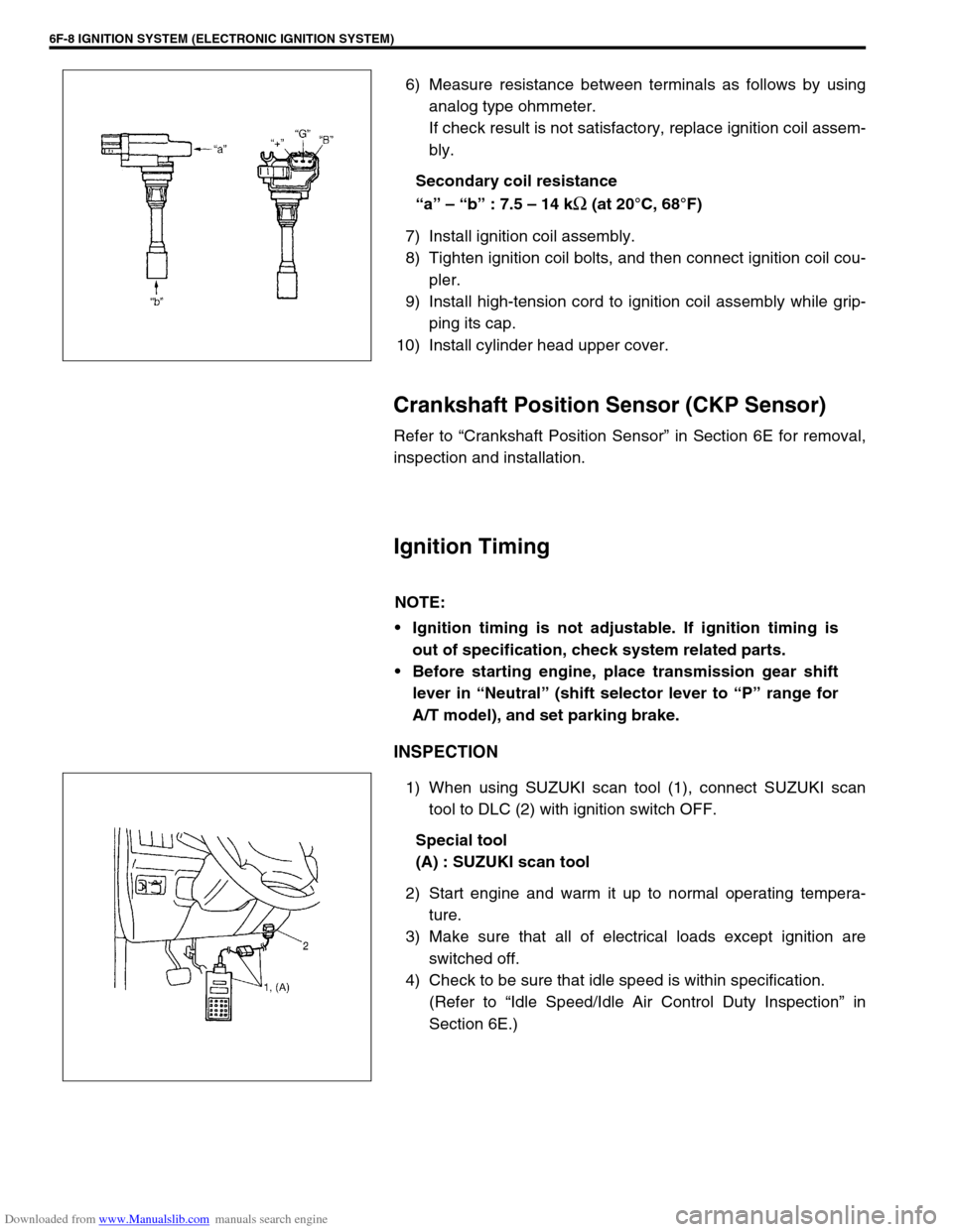
6) Measure resistance between terminals as follows by using
analog type ohmmeter.
If check result is not satisfactory, replace ignition coil assem-
bly.
Secondary coil resistance
“a” – “b” : 7.5 – 14 k
Ω (at 20°C, 68°F)
7) Install ignition coil assembly.
8) Tighten ignition coil bolts, and then connect ignition coil cou-
pler.
9) Install high-tension cord to ignition coil assembly while grip-
ping its cap.
10) Install cylinder head upper cover.
Crankshaft Position Sensor (CKP Sensor)
Refer to “Crankshaft Position Sensor” in Section 6E for removal,
inspection and installation.
Ignition Timing
INSPECTION
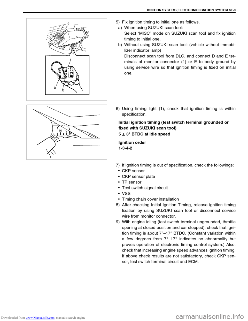
1) When using SUZUKI scan tool (1), connect SUZUKI scan
tool to DLC (2) with ignition switch OFF.
Special tool
(A) : SUZUKI scan tool
2) Start engine and warm it up to normal operating tempera-
ture.
3) Make sure that all of electrical loads except ignition are
switched off.
4) Check to be sure that idle speed is within specification.
(Refer to “Idle Speed/Idle Air Control Duty Inspection” in
Section 6E.)
NOTE:
Ignition timing is not adjustable. If ignition timing is
out of specification, check system related parts.
Before starting engine, place transmission gear shift
lever in “Neutral” (shift selector lever to “P” range for
A/T model), and set parking brake.
Page 658 of 687

Downloaded from www.Manualslib.com manuals search engine IGNITION SYSTEM (ELECTRONIC IGNITION SYSTEM 6F-9
5) Fix ignition timing to initial one as follows.
a) When using SUZUKI scan tool:
Select “MISC” mode on SUZUKI scan tool and fix ignition
timing to initial one.
b) Without using SUZUKI scan tool: (vehicle without immobi-
lizer indicator lamp)
Disconnect scan tool from DLC, and connect D and E ter-
minals of monitor connector (1) or E to body ground by
using service wire so that ignition timing is fixed on initial
one.
6) Using timing light (1), check that ignition timing is within
specification.
Initial ignition timing (test switch terminal grounded or
fixed with SUZUKI scan tool)
5
± 3° BTDC at idle speed
Ignition order
1-3-4-2
7) If ignition timing is out of specification, check the followings:
CKP sensor
CKP sensor plate
TP sensor
Test switch signal circuit
VSS
Timing chain cover installation
8) After checking Initial Ignition Timing, release ignition timing
fixation by using SUZUKI scan tool or disconnect service
wire from monitor connector.
9) With engine idling (test switch terminal ungrounded, throttle
opening at closed position and car stopped), check that igni-
tion timing is about 7°–17° BTDC. (Constant variation within
a few degrees from 7°–17° indicates no abnormality but
proves operation of electronic timing control system.) Also,
check that increasing engine speed advances ignition timing.
If above check results are not satisfactory, check CKP sen-
sor, test switch terminal circuit and ECM.
Page 687 of 687
Downloaded from www.Manualslib.com manuals search engine 6K-2 EXHAUST SYSTEM
On-Vehicle Service
COMPONENTS
Exhaust Manifold
REMOVAL AND INSTALLATION
Refer to “Exhaust Manifold” in Section 6A1 for removal and installation procedures of exhaust manifold.
INSPECTION
Check seals for deterioration or damage.
Exhaust Pipe
REMOVAL AND INSTALLATION
For replacement of exhaust pipe, exhaust center pipe, muffler or any parts used to mount or connect them, be
sure to hoist vehicle and observe WARNING under “Maintenance” and the following.
1. Exhaust pipe (Vehicle without TWC) 6. Gasket 11. Mounting nuts
2. Exhaust pipe (Vehicle with TWC) 7. Spring Tightening torque
3. Exhaust center pipe 8. Mounting Do not reuse.
4. Muffler 9. Oxygen sensor
5. Seal ring 10. Mounting bolts
CAUTION:
Exhaust pipe with three way catalytic converter should not be exposed to any impulse. Do not drop it
or hit it against something.