Page 582 of 687
Downloaded from www.Manualslib.com manuals search engine ENGINE COOLING 6B-5
Diagnosis
Condition Possible Cause Correction
Engine overheats
Loose or broken water pump belt
Not enough coolant
Faulty thermostat
Faulty water pump
Dirty or bent radiator fins
Coolant leakage on cooling system
Defective cooling fan clutch
Plugged radiator
Faulty radiator cap
Maladjusted ignition timing
Dragging brakes
Slipping clutchAdjust or replace.
Check coolant level and add as
necessary.
Replace.
Replace.
Clean or remedy.
Repair.
Check and replace as necessary.
Check and replace radiator as
necessary.
Replace.
Check system related parts.
Adjust brake.
Adjust or replace.
Page 586 of 687

Downloaded from www.Manualslib.com manuals search engine ENGINE COOLING 6B-9
9) Run engine, with radiator cap removed, until radiator upper
hose is hot.
10) With engine idling, add coolant to radiator until level reaches
the bottom of filler neck. Install radiator cap, making sure
that the ear of cap lines up with reservoir hose.
Water Pump Belt Tension
1) Inspect belt for cracks, cuts, deformation, wear and cleanli-
ness. If it is necessary to replace belt, refer to “Water Pump
Belt and Cooling Fan” in this section.
2) Check belt for tension. Belt is in proper tension when it
deflects 4.5 to 5.5 mm (0.18 – 0.22 in.) under thumb pres-
sure (about 10 kg or 22 lb.).
Water pump belt tension
“a” : 4.5 – 5.5 mm (0.18 – 0.22 in.) as deflection / 10 kg (22
lbs)
3) If belt is too tight or too loose, adjust it to proper tension by
displacing generator position.
4) Tighten generator adjusting bolt and pivot bolts as specified
torque.
Tightening torque
Generator adjusting bolt (a) : 23 N·m (2.3 kg-m, 17.0 lb-ft)
Generator pivot bolts (b) : 50 N·m (5.0 kg-m, 36.0 lb-ft)
5) Connect negative cable at battery terminal.WARNING:
Disconnect negative cable at battery before checking and
adjusting belt tension.
NOTE:
When replacing belt with a new one, adjust belt tension
to 3 – 4 mm (0.12 – 0.16 in.).
Page 590 of 687
Downloaded from www.Manualslib.com manuals search engine ENGINE COOLING 6B-13
Water Pump Belt and Cooling Fan
REMOVAL
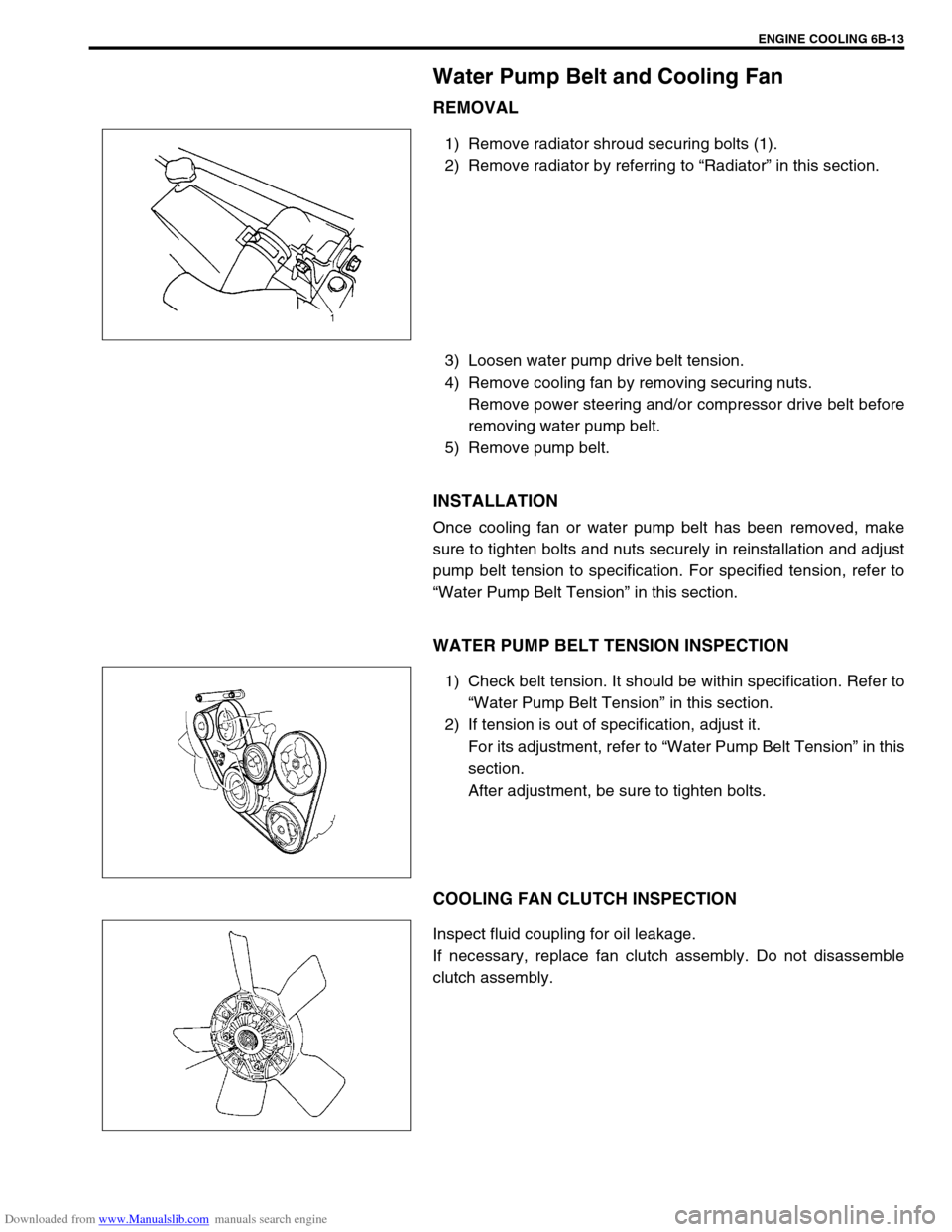
1) Remove radiator shroud securing bolts (1).
2) Remove radiator by referring to “Radiator” in this section.
3) Loosen water pump drive belt tension.
4) Remove cooling fan by removing securing nuts.
Remove power steering and/or compressor drive belt before
removing water pump belt.
5) Remove pump belt.
INSTALLATION
Once cooling fan or water pump belt has been removed, make
sure to tighten bolts and nuts securely in reinstallation and adjust
pump belt tension to specification. For specified tension, refer to
“Water Pump Belt Tension” in this section.
WATER PUMP BELT TENSION INSPECTION
1) Check belt tension. It should be within specification. Refer to
“Water Pump Belt Tension” in this section.
2) If tension is out of specification, adjust it.
For its adjustment, refer to “Water Pump Belt Tension” in this
section.
After adjustment, be sure to tighten bolts.
COOLING FAN CLUTCH INSPECTION
Inspect fluid coupling for oil leakage.
If necessary, replace fan clutch assembly. Do not disassemble
clutch assembly.
Page 592 of 687
Downloaded from www.Manualslib.com manuals search engine ENGINE COOLING 6B-15
Water Pump
COMPONENTS
REMOVAL
1) Drain cooling system.
Refer to Step 6) of “Cooling System Flush and Refill” in this
section.
2) Remove the radiator shroud.
3) Remove radiator referring to “Radiator” in this section.
4) Loosen water pump drive belt tension.
Then remove water pump pulley (2) with fan clutch (3) and
pump drive belt.
5) Remove water pump assembly (1).
1. Water pump 4. Radiator cooling fan 7. Radiator cooling fan mounting bolt
2. Water pump pulley 5. Water pump mounting bolts Tightening Torque
3. Radiator cooling fan clutch 6. Water pump pulley and fan clutch mounting nuts
1. Drain plug
Page 593 of 687
Downloaded from www.Manualslib.com manuals search engine 6B-16 ENGINE COOLING
INSPECTION
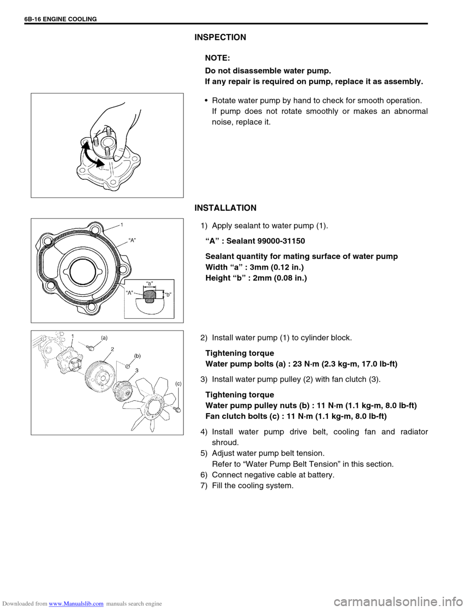
Rotate water pump by hand to check for smooth operation.
If pump does not rotate smoothly or makes an abnormal
noise, replace it.
INSTALLATION
1) Apply sealant to water pump (1).
“A” : Sealant 99000-31150
Sealant quantity for mating surface of water pump
Width “a” : 3mm (0.12 in.)
Height “b” : 2mm (0.08 in.)
2) Install water pump (1) to cylinder block.
Tightening torque
Water pump bolts (a) : 23 N·m (2.3 kg-m, 17.0 lb-ft)
3) Install water pump pulley (2) with fan clutch (3).
Tightening torque
Water pump pulley nuts (b) : 11 N·m (1.1 kg-m, 8.0 lb-ft)
Fan clutch bolts (c) : 11 N·m (1.1 kg-m, 8.0 lb-ft)
4) Install water pump drive belt, cooling fan and radiator
shroud.
5) Adjust water pump belt tension.
Refer to “Water Pump Belt Tension” in this section.
6) Connect negative cable at battery.
7) Fill the cooling system.NOTE:
Do not disassemble water pump.
If any repair is required on pump, replace it as assembly.
Page 678 of 687
Downloaded from www.Manualslib.com manuals search engine CHARGING SYSTEM 6H-11
Dismounting
1) Disconnect negative cable (3).
2) Disconnect positive cable (2).
3) Remove retainer (5).
4) Remove battery (1).
Handling
When handling battery, following safety precautions should be
followed:
Hydrogen gas is produced by battery. A flame or spark near
battery may cause the gas to ignite.
Battery fluid is highly acidic. Avoid spilling on clothing or
other fabric. Any spilled electrolyte should be flushed with
large quantity of water and cleaned immediately.
Remounting
1) Reverse removal procedure.
2) Torque battery cables to specification.
Tightening torque
Body ground bolt (a) : 8.0 N·m (0.8 kg-m, 6.0 lb-ft)
Generator
Generator belt
Refer to “Water Pump Belt and Cooling Fan” in Section 6B.
4. Body ground bolt
NOTE:
Check to be sure that ground cable has enough clear-
ance to hood panel by terminal.
Page 679 of 687
Downloaded from www.Manualslib.com manuals search engine 6H-12 CHARGING SYSTEM
Unit Repair Overhaul
Generator
Dismounting
1) Disconnect negative (–) cable (2) at battery (1).
2) Remove bolts (2) and then canister (1) together with its
bracket.
3) Disconnect “B” terminal wire (3) and coupler (2) from gener-
ator (1).
4) Remove generator belt. Refer to “Water Pump Belt and
Cooling Fan” in Section 6B.
5) Remove generator.
1. Generator adjusting bolt
2. Generator pivot bolt
3.“B” terminal
Page 680 of 687
Downloaded from www.Manualslib.com manuals search engine CHARGING SYSTEM 6H-13
Remounting
1) Mount generator on the generator bracket.
2) Tighten generator bolts.
Tightening torque
Generator pivot bolt
(a) : 23 N·m (2.3 kg-m, 16.5 lb-ft)
(b) : 50 N·m (5.0 kg-m, 36.0 lb-ft)
3) Install generator (cooling fan) belt. Refer to “Water Pump
Belt and Cooling Fan” in Section 6B.
4) Connect “B” terminal wire (3) and coupler to generator.
Tightening torque
“B” terminal outer nut of generator
(b) : 8.0 N·m (0.8 kg-m, 6.0 lb-ft)
5) Install canister.
6) Connect negative (–) cable at battery.
Disassembly and reassembly
1. Upper generator bolt (Short)
2. Lower generator bolt (Long)
1. Pulley 5. Rotor 9. Rear housing
2. Front housing 6. Stator 10. Brush
3. Bearing 7. IC regulator
4. Retainer 8. Rectifier


