Page 431 of 502
0-22
RODIUS 2005.07
6810-20
AIR CONDITIONING SYSTEM
2) Power Transistor
The power transistor controls the fan speed. It controls the blower motor operating speed
without stages by changing the current value to the base of power transistor when receiving the
fan control signal from FATC.
Front air conditioner power transistor
Rear air conditioner power transistor
(1) Inspection
If the power transistor defect code (DTC 6) is appeared, check as below.
▶
Turn the ignition switch to ON position.
Measure the voltage between terminals while changing the fan speed from stage 1 to stage
6
The specified voltage value in each stage:
1.
2.
3.
If the voltage is out of specified value, check the circuit for open. If the circuit is in normal
condition, replace the power transistor.
4.
Page 438 of 502
0-29
AIR CONDITIONING SYSTEM
RODIUS 2005.07
6810-20
6) Thermo AMP
The thermo AMP outputs the compressor ON or OFF signal to ECU to prevent evaporator from
freezing. The sensing part of the thermistor is the evaporator fin contact type.
Remove the thermo AMP and measure the voltage between terminal No. 1 and 2 on the
connector.
Check whether the output voltages (ON: approx. 12 V, off: 0 V).
If the voltage value is out of the specified value, replace the thermo AMP. If the circuit is in
normal condition, check as below.
Turn the ignition switch to ON position and turn on the air conditioner by pressing the
A/C
button. And measure the voltage between terminal A12 and A11 on the FATC controlle
r
connector. (standard: approx. 12 V)
If the voltage value cannot be measured, check the circuit for open. If the measured value is
within the specified range, replace the FATC controller.
1.
2.
3.
4.
5. If the air conditioner does not turn on, check as below.
▶
Page 445 of 502

0-8
RODIUS 2005.07
8810-01
AIR BAG SYSTEM
6) Contact Coil
The contact coil is installed between the steering wheel and the steering column and contains a
coil that enables to contact electrically between the airbag wiring harness, the driver airbag
module and the horn switch.
Turning the steering wheel more than three and onequarter turns may damage the clock
spring. The contact coil should never be disassembled and must be replaced if the airbag
have been deployed. -
Turn the label of the clock spring clockwise to lock and turn the label of the clock spring
counterclockwise approximately 2.9 ± 0.2 turns to the neutral positions with the front
wheels ahead.
Align the pointed marks “43”. -
7) Accelometer Sensor
The accelerometer sensor electronically represents the acceleration or deceleration of the
vehicle during a frontal impact.
In this electronic representation, the electrical signal is proportional to the acceleration o
r
deceleration of the vehicle.
8) Safety Sensor
The safety sensor is safety device made up of a dualcontact, electro-mechanical switch that:
Acts independently of the electronic components.
Connects the acceleration sensor in series in order to make up for the weak points in the
current electronic sensor. 1.
2.
Page 446 of 502

0-9
AIR BAG SYSTEM
RODIUS 2005.07
8810-01
9) Micro Controller
This device receives the impact signal from the sensor for vehicle impact and identifies whether
the current condition is necessary for airbag deployment or not. And then the controller sends
the specified currents to the airbag ignition circuit as needed.
This device always monitors the airbag system in conduction with the diagnostic circuit. When it
is detected any problem, it illuminates the airbag warning indicator to inform driver of the fault
and stores the fault information.
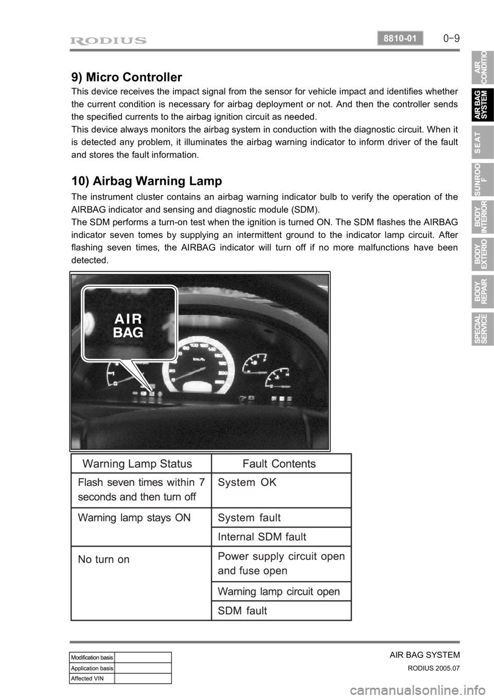
10) Airbag Warning Lamp
The instrument cluster contains an airbag warning indicator bulb to verify the operation of the
AIRBAG indicator and sensing and diagnostic module (SDM).
The SDM performs a turn-on test when the ignition is turned ON. The SDM flashes the
AIRBAG
indicator seven tomes by supplying an intermittent ground to the indicator lamp circuit.
After
flashing seven times, the AIRBAG indicator will turn off if no more malfunctions have been
detected.