Page 140 of 502

0-7
ENGINE LUBRICATION SYSTEM
RODIUS 2005.07
9210-01
1. OIL CIRCULATION
1. Oil pump
2. Oil gallery (to oil filter)
3. Oil filter
4. Oil pressure switch
5. Main oil gallery
6. Cylinder head closing cover
7. Oil gallery (at chain tensioner)
8. Oil non-return valve
9. Chain tensioner
10. Vent (chain tensioner)
11. Front closing cover (φ 17 mm)
12. Oil gallery (perpendicular to the shaft)
13. Ball (φ 6 mm)
14. Oil spray nozzle (timing chain)
15. Oil gallery (at cylinder head)
16. Ball (φ 15mm)
17. Oil restriction inner (φ 4mm)
18. Oil supply (to exhaust camshaft)19. Oil supply (to intake camshaft)
20. Oil supply (to exhaust camshaft bearing)
21. Oil supply (to intake camshaft bearing)
22. Oil gallery (oil supply to exhaust valve tappet)
23. Oil gallery (oil supply to intake valve tappet)
24. Camshaft closing cover
25. Ball (φ 8 mm)
26. Screw plug
27. Camshaft adjuster
28. Front closing cover (intake camshaft)
29. Front treaded bushing (exhaust camshaft)
30. Valve tappet
a. Oil gallery (from oil pump to oil filter)
b. Main oil gallery
c. Oil return line (oil returns to the oil pan when
replacing the filter element)
Page 147 of 502

08-9
ENGINE ELECTRIC SYSTEM
RODIUS 2005.07
1452-01
8) STARTER
Wound field starter motors have pole pieces, arranged around the armature, which are
energized by wound field coils.
Enclosed shift lever cranking motors have the shift lever mechanism and the solenoid plunge
r
enclosed in the drive housing, protecting them from exposure to dirt, icy conditions, and
splashes. In the basic circuit, solenoid windings are energized when the switch is closed. The
resulting plunger and shift lever movement causes the pinion to engage the engine flywheel
ring gear. The solenoid main contacts close. Cranking then takes place.
When the engine starts, pinion overrun protects the armature from excessive speed until the
switch is opened, at which time the return spring causes the pinion to disengage.
To prevent excessive overrun, the switch should be released immediately after the engine
starts.
9) STARTING SYSTEM
The engine electrical system includes the battery, the ignition, the starter, the alternator, and all
the related wiring.
Diagnostic tables will aid in troubleshooting system faults.
When a fault is traced to a particular component, refer to that component section of the service
manual.
The starting system circuit consists of the battery, the starter motor, the ignition switch, and all
the related electrical wiring. All of these components are connected electrically.
Page 154 of 502

09-8
RODIUS 2005.07
0452-01
ENGINE CONTROL SYSTEM
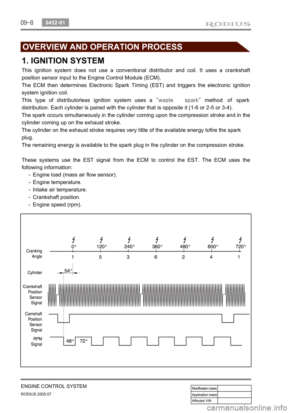
1. IGNITION SYSTEM
This ignition system does not use a conventional distributor and coil. It uses a crankshaft
position sensor input to the Engine Control Module (ECM).
The ECM then determines Electronic Spark Timing (EST) and triggers the electronic ignition
system ignition coil.
This type of distributorless ignition system uses a “waste spark” method of spark
distribution. Each cylinder is paired with the cylinder that is opposite it (1-6 or 2-5 or 3-4).
The spark occurs simultaneously in the cylinder coming upon the compression stroke and in the
cylinder coming up on the exhaust stroke.
The cylinder on the exhaust stroke requires very little of the available energy tofire the spark
plug.
The remaining energy is available to the spark plug in the cylinder on the compression stroke.
These systems use the EST signal from the ECM to control the EST. The ECM uses the
following information:
Engine load (mass air flow sensor).
Engine temperature.
Intake air temperature.
Crankshaft position.
Engine speed (rpm). -
-
-
-
-
Page 161 of 502
09-15
ENGINE CONTROL SYSTEM
RODIUS 2005.07
0452-01
2) ECU (GSL G32)
IGN COIL, CPS, AIR FLOW SENSOR, THROTTLE SENSOR, TPS ▶
Page 280 of 502
0-8
RODIUS 2005.07
4610-00
POWER STEERING SYSTEM
3. POWER STEERING PUMP
The vane type pump that is connected to engine by belt is used for the power steering system.
This pump generates and controls a proper hydraulic pressure and flows by using the flow
control valve and pressure relief valve.
The flow control valve regulates the excessive amount of discharging oil. When the steering
wheel is stationary or the oil circuit is blocked, the pressure relief valve returns the ove
r
pressurized oil to the oil reservoir.
4. OIL RESERVOIR
The oil reservoir sends the oil to the power steering pump and receives the oil from the power
steering gear.
The oil level in the reservoir depends on the steering wheel positions. therefore, measure the oil
level when the steering wheel is positioned at straight ahead direction (neutral).
Steering pump Reservoir tank
Page 356 of 502
0-4
RODIUS 2005.07
8010-10
CLUSTER
2. DESCRIPTIONS OF INDICATOR DISPLAY
1. Immobilizer indicator
2. Glow indicator
3. Winter mode indicator
4. Left turn signal indicator
5. Auto shift indicator (for automatic transmission)
6. Right turn signal indicator
7. Harzard indicator*
8. Engine check warning light
9. Cruise control indicator*
10. 4WD CHECK warning light
11. 4WD HIGH indicator
12. 4WD LOW indicator
13. Brake warning light14. Battery charge warning light
15. Seat belt reminder
16. Low fuel level warning light
17. Heated glass indicator
18. Door open warning light
19. High beam indicator
20. Engine oil pressure warning light
21. Air bag warning light
22. Water separator warning light
23. ABS warning light
24. EBD warning light
25. ESP warning light