Page 54 of 88
Wiring Diagram Ð WARN Ð/Diesel Engine
without Tachometer
GEL200B
WARNING LAMPS
EL-17
GI
MA
EM
LC
EC
FE
CL
MT
AT
TF
PD
FA
RA
BR
ST
RS
BT
HA
IDX
Page 55 of 88
GEL201B
WARNING LAMPS
Wiring Diagram Ð WARN Ð/Diesel Engine
without Tachometer (Cont'd)EL-18
Page 56 of 88
GEL202B
WARNING LAMPS
Wiring Diagram Ð WARN Ð/Diesel Engine
without Tachometer (Cont'd)EL-19
GI
MA
EM
LC
EC
FE
CL
MT
AT
TF
PD
FA
RA
BR
ST
RS
BT
HA
IDX
Page 57 of 88
GEL203B
WARNING LAMPS
Wiring Diagram Ð WARN Ð/Diesel Engine
without Tachometer (Cont'd)EL-20
Page 58 of 88
GEL204B
WARNING LAMPS
Wiring Diagram Ð WARN Ð/Diesel Engine
without Tachometer (Cont'd)EL-21
GI
MA
EM
LC
EC
FE
CL
MT
AT
TF
PD
FA
RA
BR
ST
RS
BT
HA
IDX
Page 59 of 88
Wiring Diagram Ð HORN Ð
GEL205B
HORN
EL-22
Page 76 of 88

Checking Equipment
When ordering the below equipment, contact your NISSAN distributor.
Tool name Description
NISSAN CONSULT-II
q
1CONSULT-II unit (Tester internal soft:
Resident version 3.3.0) and accesso-
ries
q
2Program card AED01C for diagnostic,
AEN00A/00B for NATS.
To confirm the best combination of
those softwares, refer to CONSULT-II
Operation Manual.
SGI083A
NOTE:
I The CONSULT-II must be used in conjunction with a program card.
CONSULT-II does not require loading (Initialization) procedure.
I Be sure the CONSULT-II is turned off before installing or removing a program card.
CONSULT-II Data Link Connector (DLC) Circuit
INSPECTION PROCEDURE
If the CONSULT-II cannot diagnose the system properly, check the following items.
Symptom Check item
CONSULT-II cannot access
any system. I
CONSULT-II DLC power supply circuit (Terminal 7) and ground circuit (Terminal 8)
(For detailed circuit, refer to ªMIL & Data Link Connectors Wiring Diagramº in EC section.)
I CONSULT-II DDL cable
CONSULT-II cannot access
individual system. (Other sys-
tems can be accessed.) I
CONSULT-II program card (Check the appropriate CONSULT-II program card for the system.
Refer to ªChecking Equipmentº above.)
I Power supply and ground circuit for the control unite of the system
(For detailed circuit, refer to wiring diagram for each system.)
I Open or short circuit between the system and CONSULT-II DLC
(For detailed circuit, refer to wiring diagram for each system.)
SGI984-B
CONSULT-II CHECKING SYSTEM
GI-4
Page 80 of 88

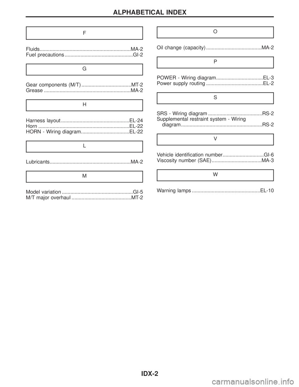
F
Fluids................................................................MA-2
Fuel precautions ................................................GI-2G
Gear components (M/T) ...................................MT-2
Grease .............................................................MA-2 H
Harness layout ................................................EL-24
Horn ................................................................EL-22
HORN - Wiring diagram..................................EL-22 L
Lubricants.........................................................MA-2M
Model variation ..................................................GI-5
M/T major overhaul ..........................................MT-2 O
Oil change (capacity) .......................................MA-2
P
POWER - Wiring diagram.................................EL-3
Power supply routing ........................................EL-2S
SRS - Wiring diagram ......................................RS-2
Supplemental restraint system - Wiringdiagram .........................................................RS-2
V
Vehicle identification number.............................GI-6
Viscosity number (SAE) ...................................MA-3 W
Warning lamps ................................................EL-10
ALPHABETICAL INDEX
IDX-2