Page 12 of 279

1. Headlight/turn signal switch (P.2-24)
2. Instrument brightness control switch
(P.2-26)
3. Driver supplemental air bag (P.1-29)/Horn
(P.2-27)
4. Meters/gauges (P.2-3)5. Cruise control main/set switch* (P.5-15)
6. Trip computer mode/setting switch (P.2-8)
7. Windshield wiper/washer switch (P.2-22)
8. Center ventilator (P.4-7)
9. Cup holder (P.2-33)
10. Passenger supplemental air bag (P.1-29)11. Side ventilators (P.4-7)
12. VDC (Vehicle dynamic control) OFF switch*
(P.2-29) or TCS (Traction control system)
OFF switch* (P.2-29)
13. Soft top operating switch (for Roadster
models) (P.3-19)
14. Fuel filler lid opener switch (P.3-13)
15. Hood lock release handle (P.3-9)
16. Fuse box (P.8-22)
17. Tilting steering wheel lock lever (P.3-15)
18. Ignition switch (P.5-6)
19. Navigation system display (P.4-2)*1 or In-
strument pocket (P.2-32)
20. Rear window and outside mirror defroster
switch (P.2-23)
21. Heater/air conditioner control (P.4-8)
22. Audio system (P.4-11)/Clock (P.2-30)
23. Heated seat switch* (P.2-28)
24. Hazard warning flasher switch (P.2-27)
25. Tray (P.2-33)
26. Power outlet (P.2-31)
*: if so equipped
*1: Refer to the separate Navigation System
Owner’s Manual.
SIC2268
INSTRUMENT PANEL
Illustrated table of contents
0-7
�
04.8.23/Z33-D/V5.0
�
Page 59 of 279

1. Headlight/turn signal switch
2. Instrument brightness control switch
3. Driver supplemental air bag/Horn
4. Meters/gauges
5. Cruise control main/set switch
(if so equipped)6. Trip computer mode/setting switch
7. Windshield wiper/washer switch
8. Center ventilator
9. Cup holder
10. Passenger supplemental air bag
11. Side ventilator12. VDC (Vehicle dynamic control) OFF switch
or TCS (Traction control system) OFF
switch
13. Soft top operating switch (for Roadster
models)
14. Fuel filler lid opener switch
15. Hood lock release handle
16. Fuse box
17. Tilting steering wheel lock lever
18. Ignition switch/steering lock
19. Navigation system display* or Instrument
pocket
20. Rear window and outside mirror defroster
switch
21. Heater/air conditioner control
22. Audio system/Clock
23. Heated seat switch (if so equipped)
24. Hazard warning flasher switch
25. Tray
26. Power outlet
*: Refer to the separate Navigation System
Owner’s Manual.
SIC2268
INSTRUMENT PANEL2-2
Instruments and controls
�
04.8.23/Z33-D/V5.0
�
Page 227 of 279

be followed.For additional information, see the
appropriate maintenance log shown in the
NISSAN Service and Maintenance Guide.BRAKE BOOSTERCheck the brake booster function as follows:
1. With the engine off, press and release the
brake pedal several times. When brake pedal
movement (distance of travel) remains the
same from one pedal application to the next,
continue on to the next step.
2. While depressing the brake pedal, start the
engine. The pedal height should drop a little.
3. With the brake pedal depressed, stop the
engine. Keeping the pedal depressed for
about 30 seconds, the pedal height should
not change.
4. Run the engine for one minute without de-
pressing the brake pedal, then turn it off.
Depress the brake pedal several times. The
pedal travel distance will decrease gradually
with each depression as the vacuum is re-
leased from the booster.
If the brakes do not operate properly, see a
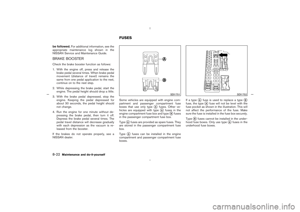
NISSAN dealer.Some vehicles are equipped with engine com-
partment and passenger compartment fuse
boxes that use only type
�A
fuses. Other ve-
hicles are equipped with type�A
fuses in the
engine compartment fuse box and type
�Bfuses
in the passenger compartment fuse box.
Type
�Afuses are provided as spare fuses. They
are stored in the passenger compartment fuse
box.
Type
�A
fuses can be installed in the engine
compartment and passenger compartment fuse
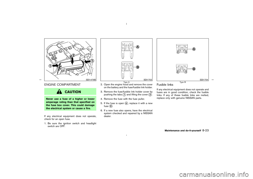
boxes.If a type
�A
fuse is used to replace a type
�B
fuse, the type
�A
fuse will not be level with the
fuse pocket as shown in the illustration. This will
not affect the performance of the fuse. Make
sure the fuse is installed in the fuse box securely.
Type
�B
fuses cannot be installed in the under-
hood fuse boxes. Only use type
�A
fuses in the
underhood fuse boxes.
SDI1751
SDI1752
FUSES
8-22
Maintenance and do-it-yourself
�
04.8.23/Z33-D/V5.0
�
Page 228 of 279

ENGINE COMPARTMENT
CAUTION
Never use a fuse of a higher or lower
amperage rating than that specified on
the fuse box cover. This could damage
the electrical system or cause a fire.
If any electrical equipment does not operate,
check for an open fuse.
1. Be sure the ignition switch and headlight
switch are OFF.2. Open the engine hood and remove the cover
on the battery and the fuse/fusible link holder.
3. Remove the fuse/fusible link holder cover by
pushing the tabs
�1
and lifting the cover
�2.
4. Remove the fuse with the fuse puller.
5. If the fuse is open
�A, replace it with a new
fuse
�B.
6. If a new fuse also opens, have the electrical
system checked and repaired by a NISSAN
dealer.
Fusible linksIf any electrical equipment does not operate and
fuses are in good condition, check the fusible
links. If any of these fusible links are melted,
replace only with genuine NISSAN parts.
SDI1479B
SDI1753
Type A
SDI1754
Type B
Maintenance and do-it-yourself
8-23
�
04.8.23/Z33-D/V5.0
�
Page 229 of 279
PASSENGER COMPARTMENT
CAUTION
Never use a fuse of a higher or lower
amperage rating than that specified on
the fuse box cover. This could damage
the electrical system or cause a fire.
If any electrical equipment does not operate,
check for an open fuse.
1. Be sure the ignition switch and the headlight
switch are OFF.2. Open the fuse box lid.
3. Pinch the fuse perpendicularly with the fuse
puller and pull it out.
4. If the fuse is open, replace it with a new fuse.
5. If a new fuse also opens, have the electrical
system checked and repaired by a NISSAN
dealer.
Replace the battery as follows:
1. Open the lid using a suitable tool.
2. Replace the battery with a new one.
Recommended battery: CR2025 or equiva-
lent
SDI1393
SDI1608
KEYFOB BATTERY
REPLACEMENT
8-24
Maintenance and do-it-yourself
�
04.8.23/Z33-D/V5.0
�