Page 389 of 788

54A-1
GROUP 54A
CHASSIS
ELECTRICAL
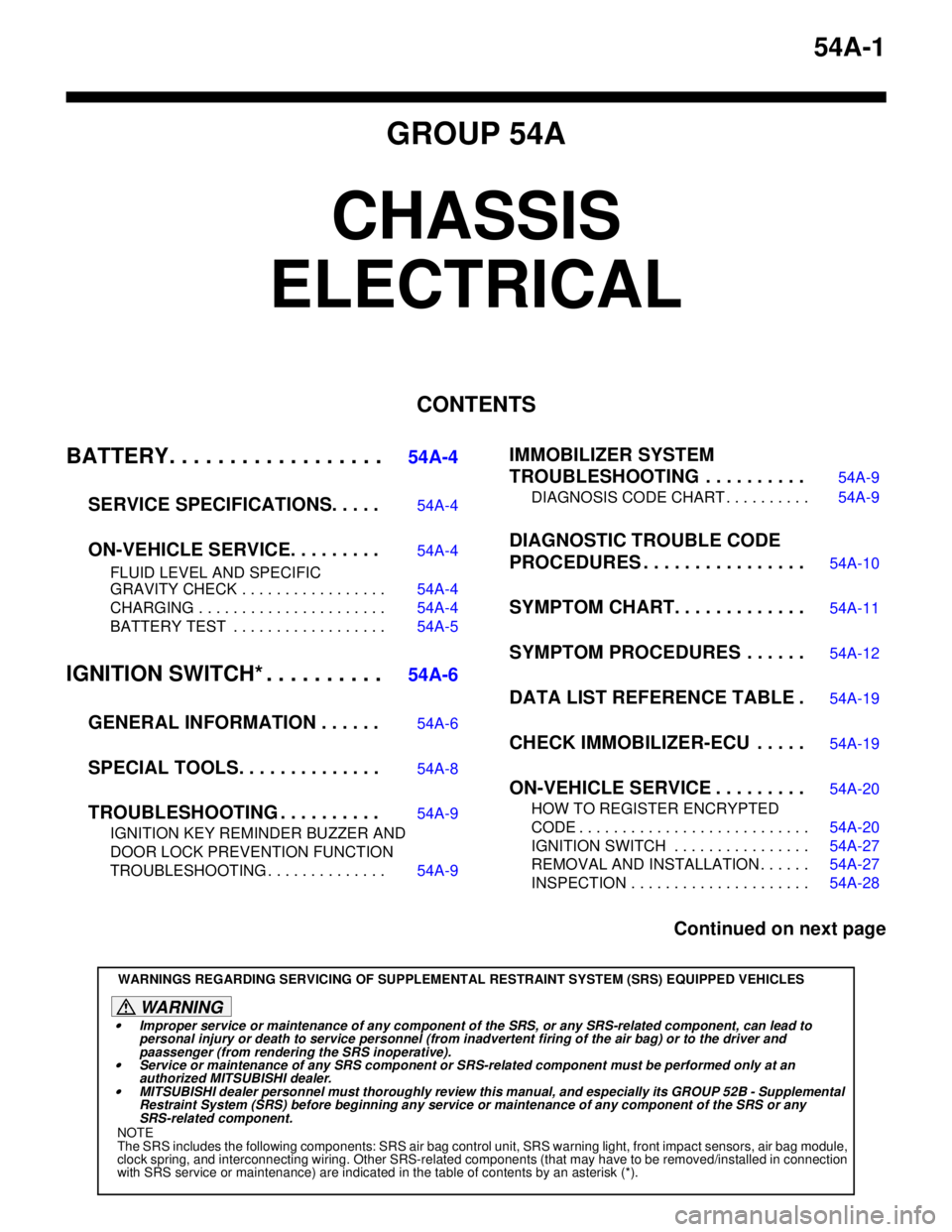
CONTENTS
BATTERY. . . . . . . . . . . . . . . . . .
54A-4
SERVICE SPECIFICATIONS. . . . .
54A-4
ON-VEHICLE SERVICE. . . . . . . . .54A-4
FLUID LEVEL AND SPECIFIC
GRAVITY CHECK . . . . . . . . . . . . . . . . . 54A-4
CHARGING . . . . . . . . . . . . . . . . . . . . . . 54A-4
BATTERY TEST . . . . . . . . . . . . . . . . . . 54A-5
IGNITION SWITCH* . . . . . . . . . .54A-6
GENERAL INFORMATION . . . . . .
54A-6
SPECIAL TOOLS. . . . . . . . . . . . . .54A-8
TROUBLESHOOTING . . . . . . . . . .54A-9
IGNITION KEY REMINDER BUZZER AND
DOOR LOCK PREVENTION FUNCTION
TROUBLESHOOTING . . . . . . . . . . . . . . 54A-9
IMMOBILIZER SYSTEM
TROUBLESHOOTING . . . . . . . . . .
54A-9
DIAGNOSIS CODE CHART . . . . . . . . . . 54A-9
DIAGNOSTIC TROUBLE CODE
PROCEDURES . . . . . . . . . . . . . . . .
54A-10
SYMPTOM CHART. . . . . . . . . . . . .54A-11
SYMPTOM PROCEDURES . . . . . .54A-12
DATA LIST REFERENCE TABLE .54A-19
CHECK IMMOBILIZER-ECU . . . . .54A-19
ON-VEHICLE SERVICE . . . . . . . . .54A-20
HOW TO REGISTER ENCRYPTED
CODE . . . . . . . . . . . . . . . . . . . . . . . . . . . 54A-20
IGNITION SWITCH . . . . . . . . . . . . . . . . 54A-27
REMOVAL AND INSTALLATION . . . . . . 54A-27
INSPECTION . . . . . . . . . . . . . . . . . . . . . 54A-28
Continued on next page
WARNINGS REGARDING SERVICING OF SUPPLEMENTAL RESTRAINT SYSTEM (SRS) EQUIPPED VEHICLES
WARNING
•Improper service or maintenance of any component of the SRS, or any SRS-related component, can lead to
personal injury or death to service personnel (from inadvertent firing of the air bag) or to the driver and
paassenger (from rendering the SRS inoperative).
•Service or maintenance of any SRS component or SRS-related component must be performed only at an
authorized MITSUBISHI dealer.
•MITSUBISHI dealer personnel must thoroughly review this manual, and especially its GROUP 52B - Supplemental
Restraint System (SRS) before beginning any service or maintenance of any component of the SRS or any
SRS-related component.
NOTE
The SRS includes the following components: SRS air bag control unit, SRS warning light, front impact sensors, air bag module,
clock spring, and interconnecting wiring. Other SRS-related components (that may have to be removed/installed in connection
with SRS service or maintenance) are indicated in the table of contents by an asterisk (*).
Page 397 of 788

IGNITION SWITCH
CHASSIS ELECTRICAL54A-9
TROUBLESHOOTING
IGNITION KEY REMINDER BUZZER AND
DOOR LOCK PREVENTION FUNCTION
TROUBLESHOOTING
M1543000701002
The ignition key reminder buzzers are controlled by
the Smart Wiring System (SWS). For
troubleshooting, refer to respective Groups below.
•Not using SWS monitor: GROUP 54B, SWS
Diagnosis P.54B-38.
•Using SWS monitor: GROUP 54C, SWS
Diagnosis P.54C-22.
IMMOBILIZER SYSTEM
TROUBLESHOOTING
DIAGNOSIS CODE CHARTM1543007100417
CAUTION
During diagnosis, a diagnosis code associated
with other system may be set when the ignition
switch is turned on with connector(s)
disconnected. On completion, confirm all
systems for diagnosis code code(s). If diagnosis
code code(s) are set, erase them all.
Use the following chart to develop proper diagnostic
strategy. MB991223
A: MB991219
B: MB991220
C: MB991221
D: MB991222Harness set
A: Test harness
B: LED harness
C: LED harness
adapter
D: ProbeMaking voltage and
resistance measurements
during troubleshooting
A: Connect pin contact
pressure inspection
B: Power circuit inspection
C: Power circuit inspection
D: Commercial tester
connection Tool Number Name Use
MB991223
A
B
C
D
AC
Diagnosis code No. Diagnosis item Reference page
11 Transponder communication system or radio interference
of encrypted codeP.54A-10.
12 Encrypted codes are not the same or are not registered
P.54A-11.
Page 398 of 788
IGNITION SWITCH
CHASSIS ELECTRICAL54A-10
DIAGNOSTIC TROUBLE CODE
PROCEDURES
Code No.11: Transponder Communication System or Radio Interference of Encrypted Code
DIAGNOSIS CODE SET CONDITION
•Diagnosis code No.11 may be set if other ignition
keys are in the vicinity of the vehicle as it is being
started.
•The transponder’s encrypted code is not sent to
the immobilizer-ECU immediately after the
ignition switch is turned to "ON" position.NOTE: Diagnosis code No.11 is always set together
with MPI system diagnosis code No.P0513.TROUBLESHOOTING HINTS
•Radio interference of the encrypted code.
•Malfunction of the transponder.
•Malfunction of the immobilizer-ECU.
HIGH-FREQUENCY
CIRCUIT IMMOBILIZER-ECU
IGNITION KEY
IGNITION KEY
RING ANTENNA
Ignition Key Ring and Immobilizer-ECU Circuit