2005 MITSUBISHI LANCER crank
[x] Cancel search: crankPage 8 of 788

GENERAL INFORMATION
ENGINE LUBRICATION12-2
GENERAL INFORMATION
M1121000100357
The lubrication method is a fully force-fed, full-flow
filtration type. The engine oil pump is a trochoid type
which is driven by the crankshaft <4G1>.The engine
oil pump is a gear type which is driven by the
crankshaft via the balancer timing belt <4G6>.
ENGINE OILS
Health Warning
Prolonged and repeated contact with mineral oil will
result in the removal of natural fats from the skin,
leading to dryness, irritation and dermatitis. In
addition, used engine oil contains potentially harmful
contaminants which may cause skin cancer.
Adequate means of skin protection and washing
facilities must be provided.
Recommended Precautions
The most effective precaution is to adapt working
practices which prevent, as far as practicable, the
risk of skin contact with mineral oils, for example by
using enclosed systems for handling used engine oil
and by degreasing components, where practicable,
before handling them. Other precautions:
•Avoid prolonged and repeated contact with oils,
particularly used engine oils.
•Wear protective clothing, including impervious
gloves where practicable.•Avoid contaminating clothes, particularly
underpants, with oil.
•Do not put oily rags in pockets, the use of overalls
without pockets will avoid this.
•Do not wear heavily soiled clothing and
oil-impregnated foot-wear. Overalls must be
cleaned regularly and kept separate from
personal clothing.
•Where there is a risk of eye contact, eye
protection should be worn, for example, chemical
goggles or face shields; in addition an eye wash
facility should be provided.
•Obtain first aid treatment immediately for open
cuts and wounds.
•Wash regularly with soap and water to ensure all
oil is removed, especially before meals (skin
cleansers and nail brushes will help). After
cleaning, the application of preparations
containing lanolin to replace the natural skin oils
is advised.
•Do not use petrol, kerosine, diesel fuel, gas oil,
thinners or solvents for cleaning skin.
•Use barrier creams, applying them before each
work period, to help the removal of oil from the
skin after work.
•If skin disorders develop, obtain medical advice
without delay.
SERVICE SPECIFICATION
M1121000300232
LUBRICANT
M1121000400433
Item Standard value
Oil pressure kPa at idle 29 or more
at 3,500 r/min 294 − 686
Item Specification
Engine oil ACEA classification A1, A2 or A3
Engine oil API classification SG or higher
Engine oil quantity L 4G1 Oil filter 0.3
To t a l 3 . 3
4G6 Oil filter 0.3
To t a l 4 . 3
Page 16 of 788

GENERAL INFORMATION
ENGINE COOLING14-2
GENERAL INFORMATION
M1141000100371The cooling system is designed to keep every part of
the engine at appropriate temperature in whatever
condition the engine may be operated. The cooling
method is of the water-cooled, pressure forced
circulation type in which the water pump pressurizes
coolant and circulates it throughout the engine. If the
coolant temperature exceeds the prescribed temperature, the thermostat opens to circulate the
coolant through the radiator as well so that the heat
absorbed by the coolant may be radiated into the air.
The water pump is of the centrifugal type and is
driven by the alternator drive belt from the
crankshaft. The radiator is the corrugated fin, down
flow type.
SERVICE SPECIFICATIONS
M1141000300416
LUBRICANT
M1141000400338
ItemSpecification
Radiator Performance kJ/h 4G13 Standard vehicles 137,720
Vehicles with capacity up radiator
(option)161,288
4G18 Standard vehicles 161,288
Vehicles with capacity up radiator
(option)181,800
4G63 181,800
A/T oil cooler Performance kJ/h 5,651
Item Standard value Limit
High-pressure valve opening pressure of radiator cap kPa 93 − 123 Minimum 83
Range of coolant antifreeze concentration of radiator % 30 − 60 -
Thermostat Valve opening temperature of
thermostat °C4G1 88 ± 1.5 -
4G6 82 ± 1.5 -
Full-opening temperature of
thermostat °C4G1 100 -
4G6 95 -
Valve lift mm 8.5 or more -
Item Specified coolant Quantity L
Engine coolant (including
condense tank)DIAQUEEN SUPER LONG LIFE COOLANT
or an equivalent4G1 5.0
4G6 7.0
Page 65 of 788

16-1
GROUP 16
ENGINE
ELECTRICAL
CONTENTS
CHARGING SYSTEM . . . . . . . .
16-2
GENERAL INFORMATION . . . . . .
16-2
SERVICE SPECIFICATIONS. . . . .16-3
SPECIAL TOOL . . . . . . . . . . . . . . .16-3
ON-VEHICLE SERVICE. . . . . . . . .16-3
ALTERNATOR OUTPUT LINE VOLTAGE
DROP TEST . . . . . . . . . . . . . . . . . . . . . 16-3
OUTPUT CURRENT TEST . . . . . . . . . . 16-5
REGULATED VOLTAGE TEST . . . . . . . 16-7
WAVEFORM CHECK USING AN
OSCILLOSCOPE . . . . . . . . . . . . . . . . . . 16-9
ALTERNATOR ASSEMBLY . . . . .16-12
REMOVAL AND INSTALLATION
<4G1> . . . . . . . . . . . . . . . . . . . . . . . . . . 16-12
REMOVAL AND INSTALLATION
<4G6> . . . . . . . . . . . . . . . . . . . . . . . . . . 16-13
DISASSEMBLY AND REASSEMBLY . . 16-15
INSPECTION . . . . . . . . . . . . . . . . . . . . . 16-17
STARTING SYSTEM . . . . . . . . .16-19
GENERAL INFORMATION . . . . . .
16-19
SERVICE SPECIFICATIONS. . . . .16-20
STARTER MOTOR ASSEMBLY . .16-21
REMOVAL AND INSTALLATION
<4G1> . . . . . . . . . . . . . . . . . . . . . . . . . . 16-21
REMOVAL AND INSTALLATION
<4G6> . . . . . . . . . . . . . . . . . . . . . . . . . . 16-22
STARTER MOTOR ASSEMBLY
INSPECTION . . . . . . . . . . . . . . . . . . . . . 16-23
DISASSEMBLY AND REASSEMBLY . . 16-26
INSPECTION . . . . . . . . . . . . . . . . . . . . . 16-27
IGNITION SYSTEM . . . . . . . . . 16-30
GENERAL INFORMATION . . . . . .
16-30
SERVICE SPECIFICATIONS . . . . .16-31
SPECIAL TOOL . . . . . . . . . . . . . . .16-31
ON-VEHICLE SERVICE . . . . . . . . .16-32
IGNITION COIL (WITH BUILT-IN
POWER TRANSISTOR) CHECK . . . . . . 16-32
RESISTIVE CORD CHECK . . . . . . . . . . 16-32
SPARK PLUG CHECK AND
CLEANING <4G1> . . . . . . . . . . . . . . . . . 16-32
SPARK PLUG CHECK AND
CLEANING <4G6> . . . . . . . . . . . . . . . . . 16-33
CAMSHAFT POSITION SENSOR
CHECK . . . . . . . . . . . . . . . . . . . . . . . . . . 16-33
CRANK ANGLE SENSOR CHECK . . . . 16-33
DETONATION SENSOR CHECK . . . . . 16-33
IGNITION SECONDARY VOLTAGE
WAVEFORM CHECK USING AN
OSCILLOSCOPE . . . . . . . . . . . . . . . . . . 16-33
IGNITION COIL RELAY CHECK . . . . . . 16-37
IGNITION COIL . . . . . . . . . . . . . . . .16-38
REMOVAL AND INSTALLATION
<4G1>. . . . . . . . . . . . . . . . . . . . . . . . . . . 16-38
REMOVAL AND INSTALLATION
<4G6>. . . . . . . . . . . . . . . . . . . . . . . . . . . 16-39
CAMSHAFT POSITION SENSOR .16-40
REMOVAL AND INSTALLATION . . . . . . 16-40
CRANKSHAFT POSITION SENSOR16-41
REMOVAL AND INSTALLATION
<4G1>. . . . . . . . . . . . . . . . . . . . . . . . . . . 16-41
REMOVAL AND INSTALLATION
<4G6>. . . . . . . . . . . . . . . . . . . . . . . . . . . 16-42
DETONATION SENSOR . . . . . . . .16-43
REMOVAL AND INSTALLATION . . . . . . 16-43
Page 76 of 788

CHARGING SYSTEM
ENGINE ELECTRICAL16-12
ALTERNATOR ASSEMBLY
REMOVAL AND INSTALLATION <4G1>M1161001400548
REMOVAL SERVICE POINT
<> ALTERNATOR ASSEMBLY
REMOVAL
Remove the alternator assembly from above the
vehicle.
Pre-removal Operation
•Under Cover Removal
•Drive Belt Removal (Refer to GROUP 11A - Crankshaft
Pulley P.11A-16).Post-installation Operation
•Drive Belt Installation (Refer to GROUP 11A - Crankshaft
Pulley P.11A-16).
•Drive Belt Tension Adjustment (Refer to GROUP 11A -
On-vehicle Service P.11A-7).
•Under Cover Installation
AC303729
1
2
4
3
44 ± 10 N·m
23 ± 2 N·m
24 ± 3 N·m12 ± 2 N·m
AB
Removal steps
1. Power steering pressure hose
clamp
2. Alternator connector and terminal3. Alternator adjusting brace
<>4. Alternator assemblyRemoval steps (Continued)
Page 77 of 788

CHARGING SYSTEM
ENGINE ELECTRICAL16-13
REMOVAL AND INSTALLATION <4G6>M1161001400559
Pre-removal Operation
•Under Cover Removal
•Strut Tower Bar Removal (Refer to GROUP 42 P.42-9).
•Drive Belt Removal (Refer to GROUP 11C - Crankshaft
Pulley P.11C-16).
•Air Cleaner Assembly Removal (Refer to GROUP 15
P.15-3).Post-installation Operation
•Air Cleaner Assembly Installation (Refer to GROUP 15
P.15-3).
•Drive Belt Installation (Refer to GROUP 11C - Crankshaft
Pulley P.11C-16).
•Strut Tower Bar Installation (Refer to GROUP 42 P.42-9).
•Drive Belt Tension Adjustment (Refer to GROUP 11C -
On-vehicle Service P.11C-7).
•Under Cover Installation
AC303826
1
2
318 ± 3 N·m
AB
Removal steps
1. Shift cable connection<>2. shift cable and shift cable bracket
assembly
3. Vehicle speed sensor connectorRemoval steps (Continued)
Page 94 of 788

IGNITION SYSTEM
ENGINE ELECTRICAL16-30
IGNITION SYSTEM
GENERAL INFORMATIONM1163000100294
This system is equipped with two ignition coils (A and
B) with built-in power transistors for the No. 1 and
No. 4 cylinders and the No. 2 and No. 3 cylinders
respectively.
Interruption of the primary current flowing in the
primary side of ignition coil A generates a high
voltage in the secondary side of ignition coil A. The
high voltage thus generated is applied to the spark
plugs of No. 1 and No. 4 cylinders to generate
sparks. At the time that the sparks are generated at
both spark plugs, if one cylinder is at the
compression stroke, the other cylinder is at the
exhaust stroke, so that ignition of the compressed
air/fuel mixture occurs only for the cylinder which is
at the compression stroke.
In the same way, when the primary current flowing in
ignition coil B is interrupted, the high voltage thus
generated is applied to the spark plugs of No. 2 and
No. 3 cylinders.The engine-ECU
turns the two power transistors inside the ignition
coils alternately on and off. This causes the primary
currents in the ignition coils to be alternately
interrupted and allowed to flow to fire the cylinders in
the order 1-3-4-2.
The engine-ECU
determines which ignition coil should be controlled
by means of the signals from the camshaft position
sensor which is incorporated in the camshaft and
from the crank angle sensor which is incorporated in
the crankshaft. It also detects the crankshaft position
in order to provide ignition at the most appropriate
timing in response to the engine operation
conditions. It also detects the crankshaft position in
order to provide ignition at the most appropriate
timing in response to the engine operation
conditions.
When the engine is cold or operated at high
altitudes, the ignition timing is slightly advanced to
provide optimum performance.
When the automatic transmission shifts gears, the
ignition timing is also retarded in order to reduce
output torque, thereby alleviating shifting shocks.
SYSTEM DIAGRAM
AK101074
Air flow sensor
<4G6> MAP sensor <4G1>
Intake air temperatur
sensor
Engine coolant
temperature sensor
Camshaft position
sensor
Crank angle sensor
Barometric pressure
sonsor <4G6>
Detonatoin sensor
Ignition switch-STEngine-A/T-
ECU Engine-ECU
Cylinder No.
23 4
AG
1 Spark plugIgnition coil AIgnition
switch
Battery
Page 97 of 788
IGNITION SYSTEM
ENGINE ELECTRICAL16-33
SPARK PLUG CHECK AND CLEANING
<4G6>
M1163004300353
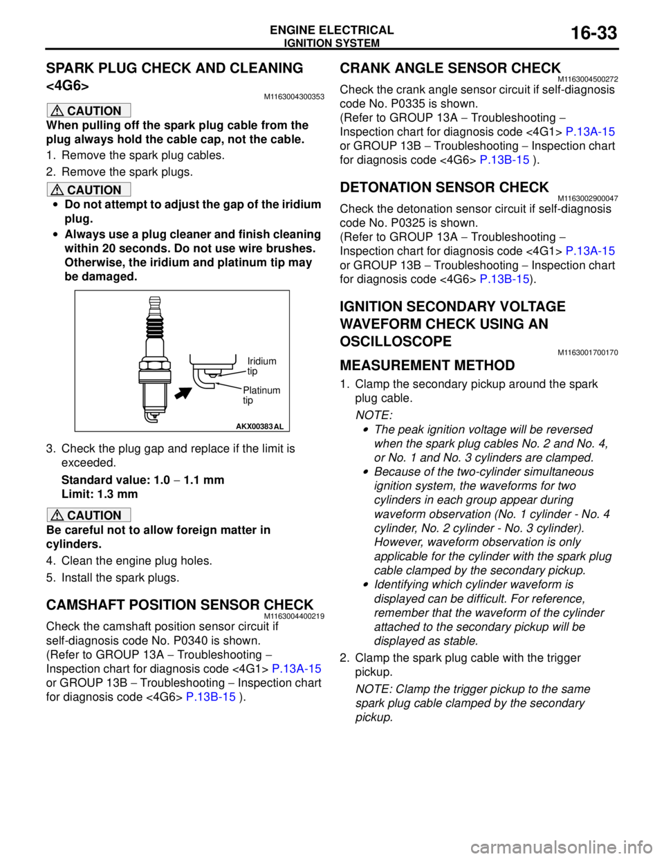
CAUTION
When pulling off the spark plug cable from the
plug always hold the cable cap, not the cable.
1. Remove the spark plug cables.
2. Remove the spark plugs.
CAUTION
•Do not attempt to adjust the gap of the iridium
plug.
•Always use a plug cleaner and finish cleaning
within 20 seconds. Do not use wire brushes.
Otherwise, the iridium and platinum tip may
be damaged.
3. Check the plug gap and replace if the limit is
exceeded.
Standard value: 1.0 − 1.1 mm
Limit: 1.3 mm
CAUTION
Be careful not to allow foreign matter in
cylinders.
4. Clean the engine plug holes.
5. Install the spark plugs.
CAMSHAFT POSITION SENSOR CHECKM1163004400219
Check the camshaft position sensor circuit if
self-diagnosis code No. P0340 is shown.
(Refer to GROUP 13A − Troubleshooting −
Inspection chart for diagnosis code <4G1> P.13A-15
or GROUP 13B − Troubleshooting − Inspection chart
for diagnosis code <4G6> P.13B-15 ).
CRANK ANGLE SENSOR CHECKM1163004500272
Check the crank angle sensor circuit if self-diagnosis
code No. P0335 is shown.
(Refer to GROUP 13A − Troubleshooting −
Inspection chart for diagnosis code <4G1> P.13A-15
or GROUP 13B − Troubleshooting − Inspection chart
for diagnosis code <4G6> P.13B-15 ).
DETONATION SENSOR CHECKM1163002900047
Check the detonation sensor circuit if self-diagnosis
code No. P0325 is shown.
(Refer to GROUP 13A − Troubleshooting −
Inspection chart for diagnosis code <4G1> P.13A-15
or GROUP 13B − Troubleshooting − Inspection chart
for diagnosis code <4G6> P.13B-15).
IGNITION SECONDARY VOLTAGE
WAVEFORM CHECK USING AN
OSCILLOSCOPE
M1163001700170
MEASUREMENT METHOD
1. Clamp the secondary pickup around the spark
plug cable.
NOTE: .
•The peak ignition voltage will be reversed
when the spark plug cables No. 2 and No. 4,
or No. 1 and No. 3 cylinders are clamped.
•Because of the two-cylinder simultaneous
ignition system, the waveforms for two
cylinders in each group appear during
waveform observation (No. 1 cylinder - No. 4
cylinder, No. 2 cylinder - No. 3 cylinder).
However, waveform observation is only
applicable for the cylinder with the spark plug
cable clamped by the secondary pickup.
•Identifying which cylinder waveform is
displayed can be difficult. For reference,
remember that the waveform of the cylinder
attached to the secondary pickup will be
displayed as stable.
2. Clamp the spark plug cable with the trigger
pickup.
NOTE: Clamp the trigger pickup to the same
spark plug cable clamped by the secondary
pickup.
AKX00383
AL
Platinum
tipIridium
tip
Page 105 of 788

IGNITION SYSTEM
ENGINE ELECTRICAL16-41
CRANKSHAFT POSITION SENSOR
REMOVAL AND INSTALLATION <4G1>
M1163003500439
Pre-removal and Post-installation Operation
•Valve Timing Belt Removal and Installation (Refer to
GROUP 11A P.11A-33).
AC208380AB
12
11 ± 1 N·m
8.8 ± 1.0 N·m
Removal steps
1. Engine crank angle sensor
2. Crank angle sensor connector
bracket