Page 47 of 788
Page 48 of 788
Page 50 of 788
Page 51 of 788
Page 53 of 788
15-1
GROUP 15
INTAKE AND
EXHAUST
CONTENTS
GENERAL INFORMATION . . . . . . . .15-2
SERVICE SPECIFICATION . . . . . . . .15-2
SPECIAL TOOL . . . . . . . . . . . . . . . . .15-2
AIR CLEANER . . . . . . . . . . . . . . . . . .15-3
REMOVAL AND INSTALLATION . . . . . . . . 15-3
INLET MANIFOLD . . . . . . . . . . . . . . .15-5
REMOVAL AND INSTALLATION <4G1> . . 15-5REMOVAL AND INSTALLATION <4G6> . . 15-6
INSPECTION . . . . . . . . . . . . . . . . . . . . . . . . 15-7
EXHAUST MANIFOLD . . . . . . . . . . . .15-7
REMOVAL AND INSTALLATION <4G1> . . 15-7
REMOVAL AND INSTALLATION <4G6> . . 15-9
INSPECTION . . . . . . . . . . . . . . . . . . . . . . . . 15-10
EXHAUST PIPE AND MAIN
MUFFLER . . . . . . . . . . . . . . . . . . . . . .15-11
REMOVAL AND INSTALLATION . . . . . . . . 15-11
Page 56 of 788
AIR CLEANER
INTAKE AND EXHAUST15-4
AC303619
4.0 ± 1.0 N·m 4.0 ± 1.0 N·m10*9*4
1*5
11
12 ± 1 N·m
9.0 ± 1.0 N·m 9.0 ± 1.0 N·m
AB
12 ± 1 N·m
Clamp
8*
3* <4G6>
6 7
N
2
8.8 ± 1.0 N·m
Removal steps
1. Air cleaner intake duct
2. Air cleaner air flow sensor connector
<4G6>
3. Air cleaner assembly <4G1> or Air
cleaner and air cleaner air flow sensor
assembly <4G6>
4. Rocker cover breather hose
connection
5. Air cleaner to throttle body duct6. Air cleaner air flow sensor <4G6>
7. Air cleaner air flow sensor gasket
<4G6>
8. Air cleaner cover
9. Air cleaner element
10. Air cleaner body assembly
11. Air cleaner bracketRemoval steps (Continued)
Page 57 of 788

INLET MANIFOLD
INTAKE AND EXHAUST15-5
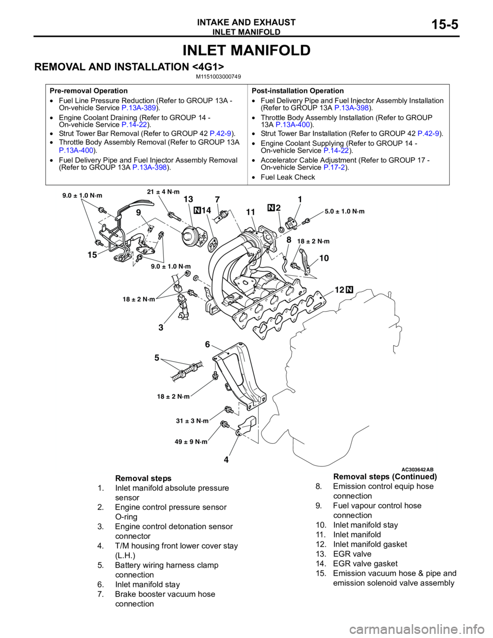
INLET MANIFOLD
REMOVAL AND INSTALLATION <4G1>M1151003000749
Pre-removal Operation
•Fuel Line Pressure Reduction (Refer to GROUP 13A -
On-vehicle Service P.13A-389).
•Engine Coolant Draining (Refer to GROUP 14 -
On-vehicle Service P.14-22).
•Strut Tower Bar Removal (Refer to GROUP 42 P.42-9).
•Throttle Body Assembly Removal (Refer to GROUP 13A
P.13A-400).
•Fuel Delivery Pipe and Fuel Injector Assembly Removal
(Refer to GROUP 13A P.13A-398).Post-installation Operation
•Fuel Delivery Pipe and Fuel Injector Assembly Installation
(Refer to GROUP 13A P.13A-398).
•Throttle Body Assembly Installation (Refer to GROUP
13A P.13A-400).
•Strut Tower Bar Installation (Refer to GROUP 42 P.42-9).
•Engine Coolant Supplying (Refer to GROUP 14 -
On-vehicle Service P.14-22).
•Accelerator Cable Adjustment (Refer to GROUP 17 -
On-vehicle Service P.17-2).
•Fuel Leak Check
AC303642AB
15
3
6
5
412 10 71
2
11
913
14
21 ± 4 N·m
9.0 ± 1.0 N·m
9.0 ± 1.0 N·m
18 ± 2 N·m
18 ± 2 N·m18 ± 2 N·m5.0 ± 1.0 N·m
31 ± 3 N·m
49 ± 9 N·m
N
N
N
8
Removal steps
1. Inlet manifold absolute pressure
sensor
2. Engine control pressure sensor
O-ring
3. Engine control detonation sensor
connector
4. T/M housing front lower cover stay
(L.H.)
5. Battery wiring harness clamp
connection
6. Inlet manifold stay
7. Brake booster vacuum hose
connection8. Emission control equip hose
connection
9. Fuel vapour control hose
connection
10. Inlet manifold stay
11. Inlet manifold
12. Inlet manifold gasket
13. EGR valve
14. EGR valve gasket
15. Emission vacuum hose & pipe and
emission solenoid valve assembly Removal steps (Continued)
Page 58 of 788

INLET MANIFOLD
INTAKE AND EXHAUST15-6
REMOVAL AND INSTALLATION <4G6>M1151003001236
Pre-removal Operation
•Fuel Line Pressure Reduction (Refer to GROUP 13A -
On-vehicle Service P.13A-389).
•Engine Coolant Draining (Refer to GROUP 14 -
On-vehicle Service P.14-22).
•Strut Tower Bar Removal (Refer to GROUP 42 P.42-9).
•Throttle Body Assembly Removal (Refer to GROUP 13B
P.13B-336).
•Fuel Delivery Pipe and Fuel Injector Assembly Removal
(Refer to GROUP 13B P.13B-334).Post-installation Operation
•Fuel Delivery Pipe and Fuel Injector Assembly Installation
(Refer to GROUP 13B P.13B-334).
•Throttle Body Assembly Installation (Refer to GROUP
13B P.13B-336).
•Strut Tower Bar Installation (Refer to GROUP 42 P.42-9).
•Engine Coolant Supplying (Refer to GROUP 14 -
On-vehicle Service P.14-22).
•Accelerator Cable Adjustment (Refer to GROUP 17 -
On-vehicle Service P.17-2).
•Fuel Leak Check
AC303657
9.0 ± 1.0 N·m11 ± 1 N·m
20 ± 2 N·m
31 ± 3 N·m 36 ± 6 N·m
20 ± 2 N·m
20 ± 2 N·m
36 ± 6 N·m
36 ± 6 N·m
11
9 10 212
N1413N
AB
5.0 ± 1.0 N·m
3
1
11 ± 1 N·m
4
N
13 ± 1 N·m
5
6
(Engine oil)
7
8
Removal steps
1. Emission control equip hose
connector
2. Brake booster vacuum hose
connection
3. Earth cable connection4. Engine control detonation sensor
connector
5. Engine oil level gauge and guide
assembly
6. Engine oil filler O-ring
7. Emission vacuum hose connectionRemoval steps (Continued)