2005 MITSUBISHI 380 ECU
[x] Cancel search: ECUPage 1442 of 1500
DRIVE SHAFT ASSEMBLY
FRONT AXLE26-25
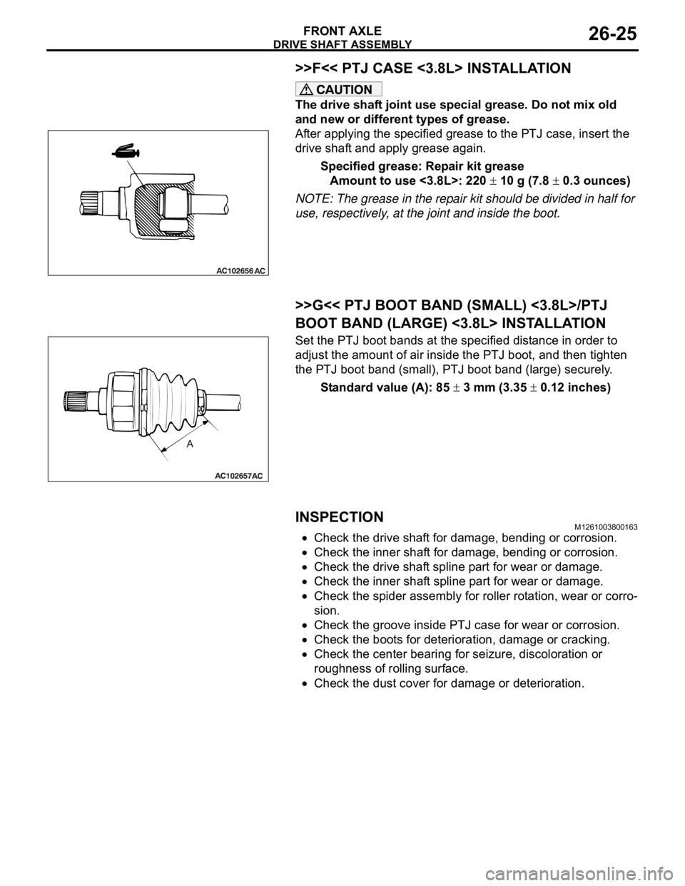
>>F<< PTJ CASE <3.8L> INSTALLATION
The drive shaft joint use special grease. Do not mix old
and new or different types of grease.
After applying the specified grease to the PTJ case, insert the
drive shaft and apply grease again.
Specified grease: Repair kit grease
Amount to use <3.8L>: 220
10 g (7.8 0.3 ounces)
NOTE: The grease in the repair kit should be divided in half for
use, respectively, at the joint and inside the boot.
.
>>G<< PTJ BOOT BAND (SMALL) <3.8L>/PTJ
BOOT BAND (LARGE) <3.8L> INSTALLATION
Set the PTJ boot bands at the specified distance in order to
adjust the amount of air inside the PTJ boot, and then tighten
the PTJ boot band (small), PTJ boot band (large) securely.
Standard value (A): 85
3 mm (3.35 0.12 inches)
INSPECTIONM1261003800163
Check the drive shaft for damage, bending or corrosion.
Check the inner shaft for damage, bending or corrosion.
Check the drive shaft spline part for wear or damage.
Check the inner shaft spline part for wear or damage.
Check the spider assembly for roller rotation, wear or corro-
sion.
Check the groove inside PTJ case for wear or corrosion.
Check the boots for deterioration, damage or cracking.
Check the center bearing for seizure, discoloration or
roughness of rolling surface.
Check the dust cover for damage or deterioration.
Page 1444 of 1500
DRIVE SHAFT ASSEMBLY
FRONT AXLE26-27
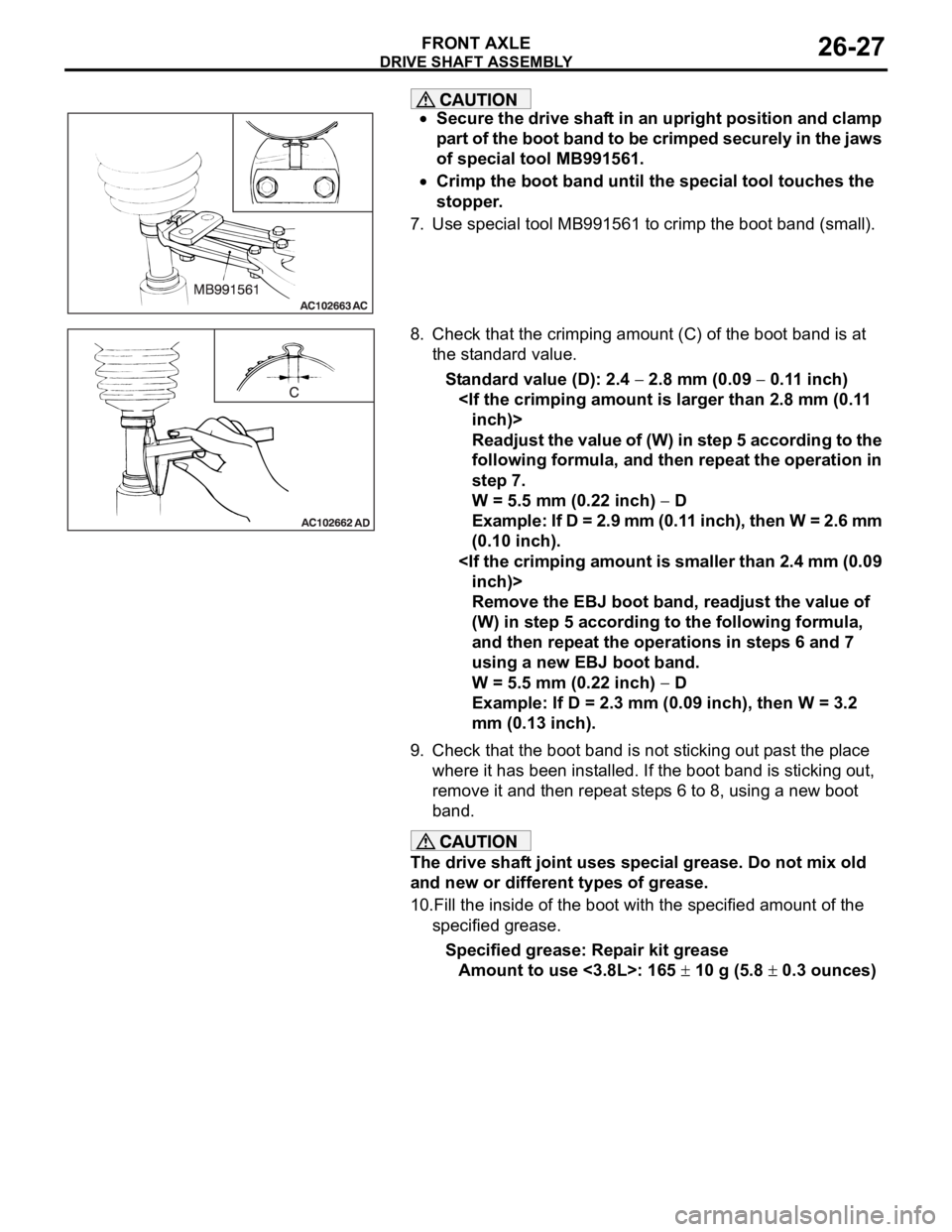
Secure the drive shaft in an upright position and clamp
part of the boot band to be crimped securely in the jaws
of special tool MB991561.
Crimp the boot band until the special tool touches the
stopper.
7. Use special tool MB991561 to crimp the boot band (small).
8. Check that the crimping amount (C) of the boot band is at
the standard value.
Standard value (D): 2.4
2.8 mm (0.09 0.11 inch)
Readjust the value of (W) in step 5 according to the
following formula, and then repeat the operation in
step 7.
W = 5.5 mm (0.22 inch)
D
Example: If D = 2.9 mm (0.11 inch), then W = 2.6 mm
(0.10 inch).
Remove the EBJ boot band, readjust the value of
(W) in step 5 according to the following formula,
and then repeat the operations in steps 6 and 7
using a new EBJ boot band.
W = 5.5 mm (0.22 inch)
D
Example: If D = 2.3 mm (0.09 inch), then W = 3.2
mm (0.13 inch).
9. Check that the boot band is not sticking out past the place
where it has been installed. If the boot band is sticking out,
remove it and then repeat steps 6 to 8, using a new boot
band.
The drive shaft joint uses special grease. Do not mix old
and new or different types of grease.
10.Fill the inside of the boot with the specified amount of the
specified grease.
Specified grease: Repair kit grease
Amount to use <3.8L>: 165
10 g (5.8 0.3 ounces)
Page 1453 of 1500
REAR AXLE HUB ASSEMBLY
REAR AXLE27-6
REAR AXLE HUB ASSEMBLY
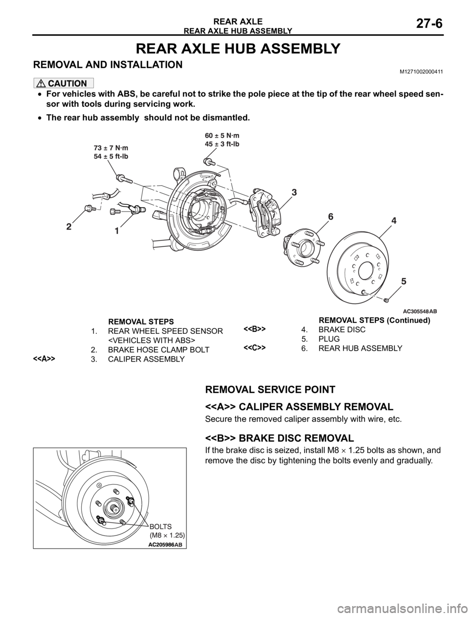
REMOVAL AND INSTALLATIONM1271002000411
For vehicles with ABS, be careful not to strike the pole piece at the tip of the rear wheel speed sen-
sor with tools during servicing work.
The rear hub assembly should not be dismantled.
REMOVAL SERVICE POINT
.
<> CALIPER ASSEMBLY REMOVAL
Secure the removed caliper assembly with wire, etc.
.
<> BRAKE DISC REMOVAL
If the brake disc is seized, install M8 1.25 bolts as shown, and
remove the disc by tightening the bolts evenly and gradually.
.
REMOVAL STEPS
1. REAR WHEEL SPEED SENSOR
2. BRAKE HOSE CLAMP BOLT
<>3. CALIPER ASSEMBLY
<>4. BRAKE DISC
5. PLUG
<
Page 1460 of 1500
23A-1
GROUP 23A
AUTOMATIC
TRANSMISSION
CONTENTS
GENERAL DESCRIPTION. . . . . . . . .23A-3
AUTOMATIC TRANSMISSION
DIAGNOSIS . . . . . . . . . . . . . . . . . . . .23A-12
DIAGNOSTIC TROUBLESHOOTING FLOW23A-12
INTRODUCTION TO A/T DIAGNOSIS . . . . 23A-12
A/T DIAGNOSTIC TROUBLESHOOTING
STRATEGY . . . . . . . . . . . . . . . . . . . . . . . . . 23A-13
DIAGNOSTIC FUNCTION . . . . . . . . . . . . . 23A-13
HOW TO INITIALIZE A/T LEARNING
VALUE . . . . . . . . . . . . . . . . . . . . . . . . . . . . 23A-17
FAIL-SAFE/BACKUP FUNCTION. . . . . . . . 23A-18
ROAD TEST . . . . . . . . . . . . . . . . . . . . . . . . 23A-19
TORQUE CONVERTER STALL TEST . . . . 23A-25
HYDRAULIC PRESSURE TESTS . . . . . . . 23A-26
HYDRAULIC CIRCUIT . . . . . . . . . . . . . . . . 23A-32LINE PRESSURE ADJUSTMENT . . . . . . . . 23A-33
DIAGNOSTIC TROUBLE CODE CHART . . 23A-34
SYMPTOM CHART . . . . . . . . . . . . . . . . . . . 23A-35
DIAGNOSTIC TROUBLE CODE
PROCEDURES . . . . . . . . . . . . . . . . . . . . . . 23A-36
SYMPTOM PROCEDURES . . . . . . . . . . . . 23A-218
DATA LIST REFERENCE TABLE . . . . . . . . 23A-271
ACTUATOR TEST REFERENCE TABLE . . 23A-276
A/T-ECU TERMINAL VOLTAGE REFERENCE
CHART FOR TRANSMISSION OPERATION23A-278
A/T-ECU TERMINAL RESISTANCE AND
CONTINUITY INSPECTION CHART . . . . . 23A-284
INSPECTION PROCEDURE USING AN
OSCILLOSCOPE . . . . . . . . . . . . . . . . . . . . 23A-285
Continued on next page
WARNINGS REGARDING SERVICING OF SUPPLEMENTAL RESTRAINT SYSTEM (SRS) EQUIPPED VEHICLES
Page 1467 of 1500
GENERAL DESCRIPTION
AUTOMATIC TRANSMISSION23A-8
FEATURES
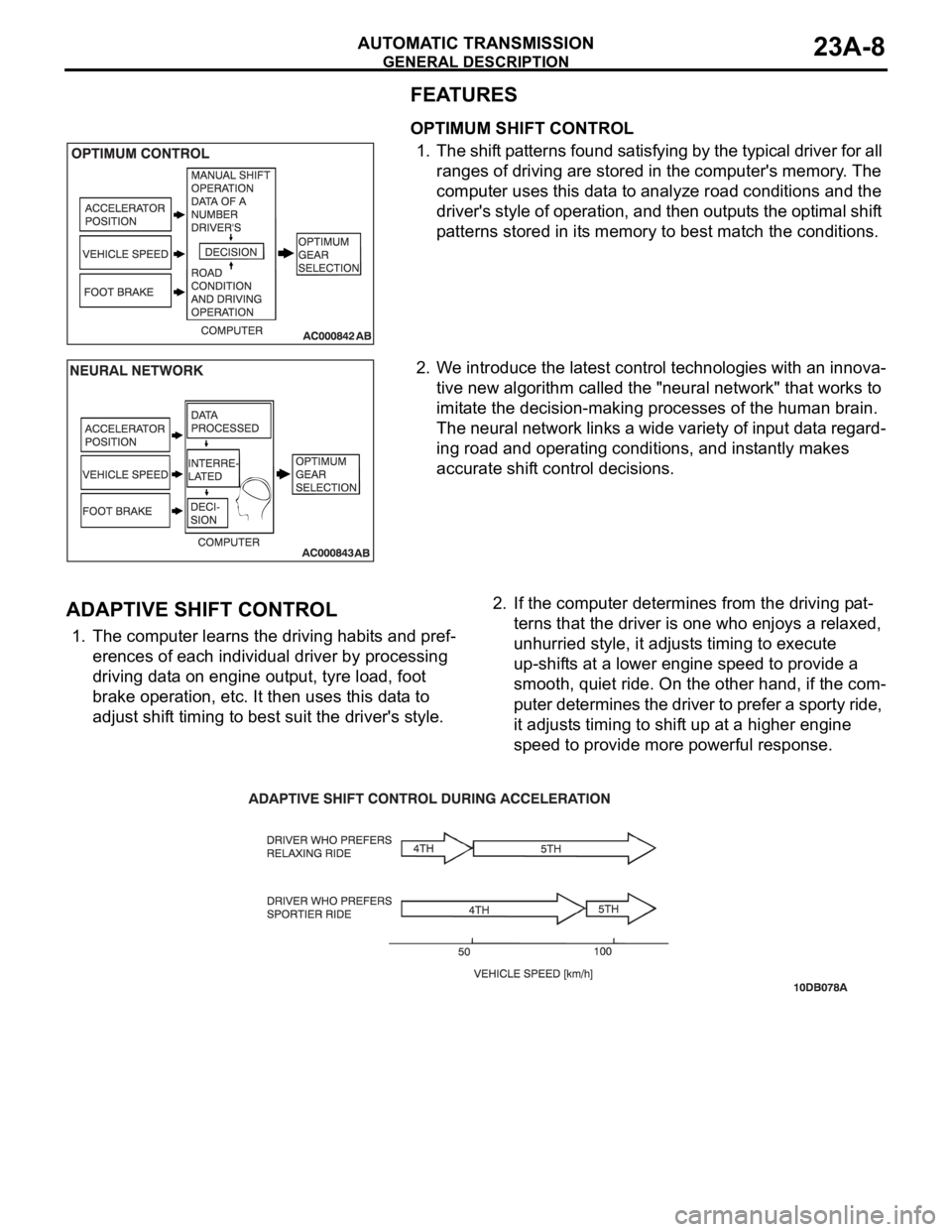
OPTIMUM SHIFT CONTROL
1. The shift patterns found satisfying by the typical driver for all
ranges of driving are stored in the computer's memory. The
computer uses this data to analyze road conditions and the
driver's style of operation, and then outputs the optimal shift
patterns stored in its memory to best match the conditions.
2. We introduce the latest control technologies with an innova-
tive new algorithm called the "neural network" that works to
imitate the decision-making processes of the human brain.
The neural network links a wide variety of input data regard-
ing road and operating conditions, and instantly makes
accurate shift control decisions.
.
ADAPTIVE SHIFT CONTROL
1. The computer learns the driving habits and pref-
erences of each individual driver by processing
driving data on engine output, tyre load, foot
brake operation, etc. It then uses this data to
adjust shift timing to best suit the driver's style.2. If the computer determines from the driving pat-
terns that the driver is one who enjoys a relaxed,
unhurried style, it adjusts timing to execute
up-shifts at a lower engine speed to provide a
smooth, quiet ride. On the other hand, if the com-
puter determines the driver to prefer a sporty ride,
it adjusts timing to shift up at a higher engine
speed to provide more powerful response.
.
Page 1471 of 1500
AUTOMATIC TRANSMISSION DIAGNOSIS
AUTOMATIC TRANSMISSION23A-12
AUTOMATIC TRANSMISSION DIAGNOSIS
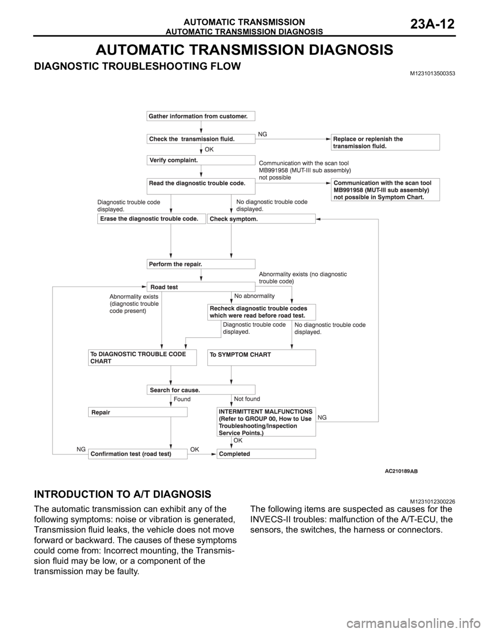
DIAGNOSTIC TROUBLESHOOTING FLOWM1231013500353
INTRODUCTION TO A/T DIAGNOSISM1231012300226
The automatic transmission can exhibit any of the
following symptoms: noise or vibration is generated,
Transmission fluid leaks, the vehicle does not move
forward or backward. The causes of these symptoms
could come from: Incorrect mounting, the Transmis-
sion fluid may be low, or a component of the
transmission may be faulty. The following items are suspected as causes for the
INVECS-II troubles: malfunction of the A/T-ECU, the
sensors, the switches, the harness or connectors.
Page 1472 of 1500
AUTOMATIC TRANSMISSION DIAGNOSIS
AUTOMATIC TRANSMISSION23A-13
A/T DIAGNOSTIC TROUBLESHOOTING STRATEGYM1231007600339
Use these steps to plan your diagnostic strategy. If
you follow them carefully, you will find most A/T mal-
functions.
1. Gather as much information as possible about the
complaint from the customer.
2. Verify that the condition described by the
customer exists.
3. Check the vehicle for any A/T Diagnostic Trouble
Codes (DTCs).
4. If you can not verify the condition and there are no
DTCs, the malfunction is intermittent. For
information on how to cope with intermittent
malfunctions, refer to GROUP 00, How to Use
Troubleshooting/Inspection Service Points
How
to Cope with Intermittent Malfunction P.00-14.
5. If you can verify the condition but there are no
DTCs, or the system can not communicate with
diagnostic tool, refer to the Symptom Chart
P.23A-35.6. If there is a DTC, record the number of the code,
then erase the code from memory using
diagnostic tool.
7. Reconfirm the symptom with a Road Test.
8. If a DTC is set again, go to the Inspection Chart
for Diagnostic Trouble Codes.
9. If a DTC is not set again, the malfunction is
intermittent. For information on how to cope with
intermittent malfunctions, refer to GROUP 00,
How to Use Troubleshooting/Inspection Service
Points
How to Cope with Intermittent
Malfunction P.00-14.
10.After repairs are completed, conduct a Road Test
duplicating the complaint conditions to confirm the
malfunction has been eliminated.
DIAGNOSTIC FUNCTIONM1231022500135
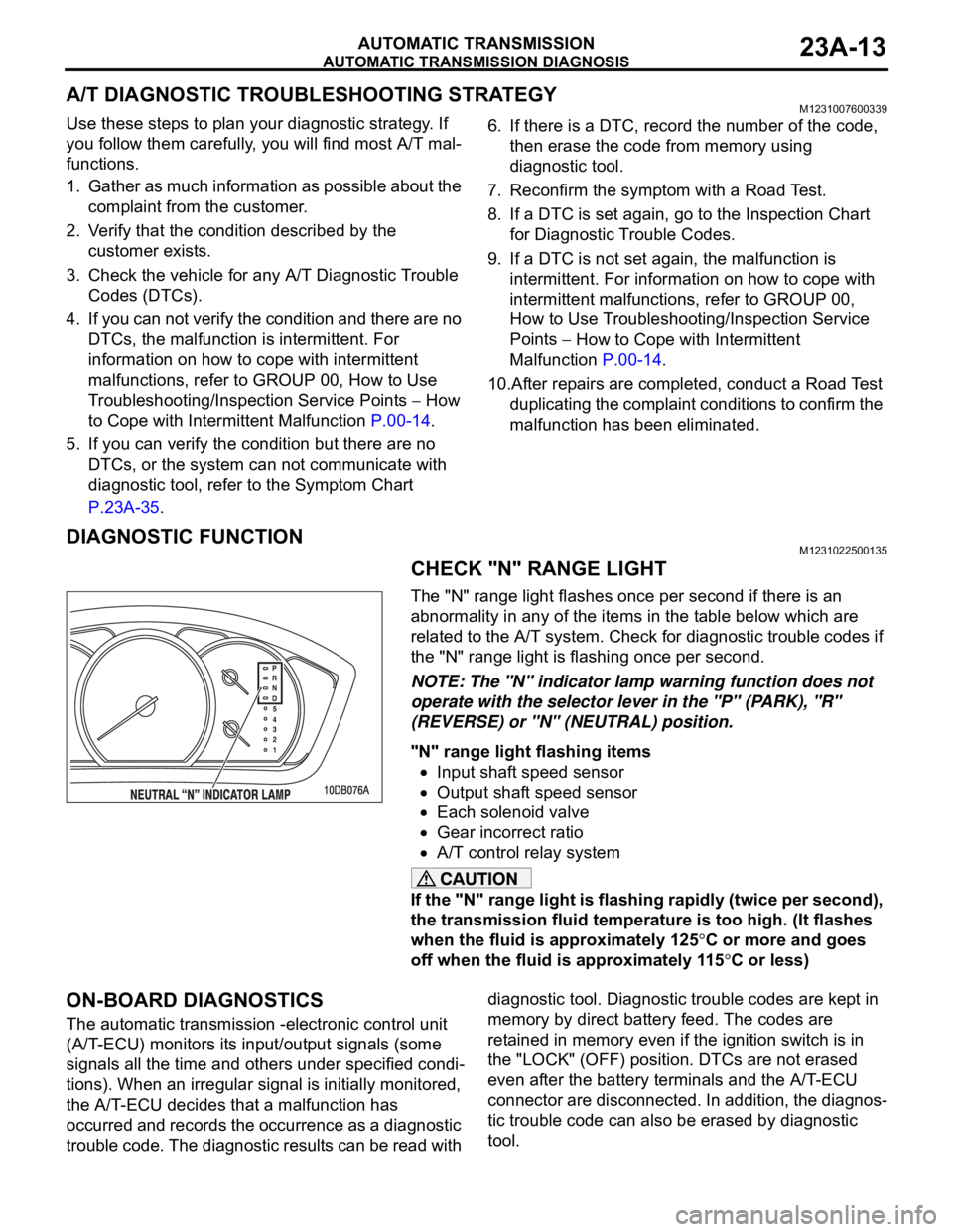
CHECK "N" RANGE LIGHT
The "N" range light flashes once per second if there is an
abnormality in any of the items in the table below which are
related to the A/T system. Check for diagnostic trouble codes if
the "N" range light is flashing once per second.
NOTE: The "N" indicator lamp warning function does not
operate with the selector lever in the "P" (PARK), "R"
(REVERSE) or "N" (NEUTRAL) position.
"N" range light flashing items
Input shaft speed sensor
Output shaft speed sensor
Each solenoid valve
Gear incorrect ratio
A/T control relay system
If the "N" range light is flashing rapidly (twice per second),
the transmission fluid temperature is too high. (It flashes
when the fluid is approximately 125
C or more and goes
off when the fluid is approximately 115
C or less)
ON-BOARD DIAGNOSTICS
The automatic transmission -electronic control unit
(A/T-ECU) monitors its input/output signals (some
signals all the time and others under specified condi-
tions). When an irregular signal is initially monitored,
the A/T-ECU decides that a malfunction has
occurred and records the occurrence as a diagnostic
trouble code. The diagnostic results can be read with diagnostic tool. Diagnostic trouble codes are kept in
memory by direct battery feed. The codes are
retained in memory even if the ignition switch is in
the "LOCK" (OFF) position. DTCs are not erased
even after the battery terminals and the A/T-ECU
connector are disconnected. In addition, the diagnos-
tic trouble code can also be erased by diagnostic
tool.
Page 1477 of 1500

AUTOMATIC TRANSMISSION DIAGNOSIS
AUTOMATIC TRANSMISSION23A-18
FAIL-SAFE/BACKUP FUNCTIONM1231008300234
When a malfunction of a main sensor or actuator is
detected by the A/T-ECU, the transmission is con-
trolled by pre-set control logic to maintain safe condi-
tions for driving.The following table shows how the fail-safe/backup
function affects vehicle driveability and operation.
MALFUNCTIONING ITEM JUDGEMENT
CONDITIONCONTROL DEFAULT DURING MALFUNCTION
Input shaft speed sensor If no output pulse
from the input shaft
speed sensor is
detected for one
second or more
when the vehicle
speed is 30 km/h (19
mph) or greater.The diagnostic trouble code is recorded when the
malfunction occurs during 4 monitoring periods in
one drive cycle. When the judgment condition is
met, the transmission holds 3rd gear or 2nd gear,
depending on speed, as a fail-safe.
Output shaft speed sensor The output signal
from the output shaft
speed sensor is not
present for one
second or more
while the vehicle is
driven.The diagnostic trouble code is recorded when the
malfunction occurs during 4 monitoring periods in
one drive cycle. When the judgment condition is
met, the transmission holds 3rd gear or 2nd gear,
depending on speed, as a fail-safe.
Low-reverse solenoid valve Solenoid valve
resistance is below
2.7 ohms for 0.32
seconds.The diagnostic trouble code is recorded when the
malfunction occurs during 5 monitoring periods in
one drive cycle. When the judgment condition is
met, the A/T control relay is turned off. The
transmission will only operate in 3rd and reverse
gears until the system is repaired. Underdrive solenoid valve
Second solenoid valve
Overdrive solenoid valve
Reduction (RED) solenoid valve
Damper control clutch (DCC)
solenoid valve
Incomplete shifting 1st The gear ratio value
from the output shaft
speed sensor is not
the same as the
output from the input
shaft speed sensor
for one second after
shifting has been
completed.The diagnostic trouble code is recorded when the
malfunction occurs during 5 monitoring periods in
one drive cycle. When the judgment condition is
met, the A/T control relay is turned off. The
transmission will only operate in 3rd and reverse
gears until the system is repaired. 2nd
3rd
4th
5th
Reverse
A/T control relay A/T control relay
voltage is less than
seven volts for 0.1
second after the
ignition switch is
turned "ON."The A/T control relay is switched off. The
transmission will only operate in 3rd and reverse
gears until the system is repaired.
Malfunction in the A/T-ECU Malfunction has
occurred in the
A/T-ECU.The A/T control relay is switched off. The
transmission will only operate in 3rd and reverse
gears until the system is repaired.