Page 1318 of 1500
TRACTION CONTROL SYSTEM (TCL) DIAGNOSIS
TRACTION CONTROL SYSTEM (TCL)13C-39
RESISTANCE AND CONTINUITY BETWEEN
ABS-ECU AND WHEEL SPEED SENSOR
HARNESS-SIDE CONNECTOR TERMINALS
.
Required Special Tools:
MB991219: Inspection Test Harness
MB991223: Harness Set
1. Disconnect the ABS/TCL-ECU connector A-02 and the
related wheel speed sensor connector, then turn the ignition
switch to the "LOCK" (OFF) position.
2. Measure the resistance and continuity between the
ABS/TCL-ECU wiring harness-side connector A-02 and the
Wheel Speed Sensor connectors using the Inspection test
harness MB991219 (by inserting probe) and an ohmmeter
between terminals shown in the table below.
NOTE: The special tool (Inspection test harness) MB991219
for connector pin contact pressure should be used. The test
probe should never be forcibly inserted, as it may cause a
defective contact.
3. The terminal layout is shown in the table below.
Page 1319 of 1500
TRACTION CONTROL SYSTEM (TCL) DIAGNOSIS
TRACTION CONTROL SYSTEM (TCL)13C-40
SIGNAL TERMINAL NO. NORMAL CONDITION
ABS (A-02) SENSOR
FR wheel speed sensor
(A-01)9 2 Less than 2 ohms
10 1 Less than 2 ohms
RR wheel speed sensor
(D-30)8 1 Less than 2 ohms
19 2 Less than 2 ohms
FL wheel speed sensor
(A-04)16 2 Less than 2 ohms
5 1 Less than 2 ohms
RL wheel speed sensor
(D-31)6 1 Less than 2 ohms
17 2 Less than 2 ohms
Page 1320 of 1500

TRACTION CONTROL SYSTEM (TCL) DIAGNOSIS
TRACTION CONTROL SYSTEM (TCL)13C-41
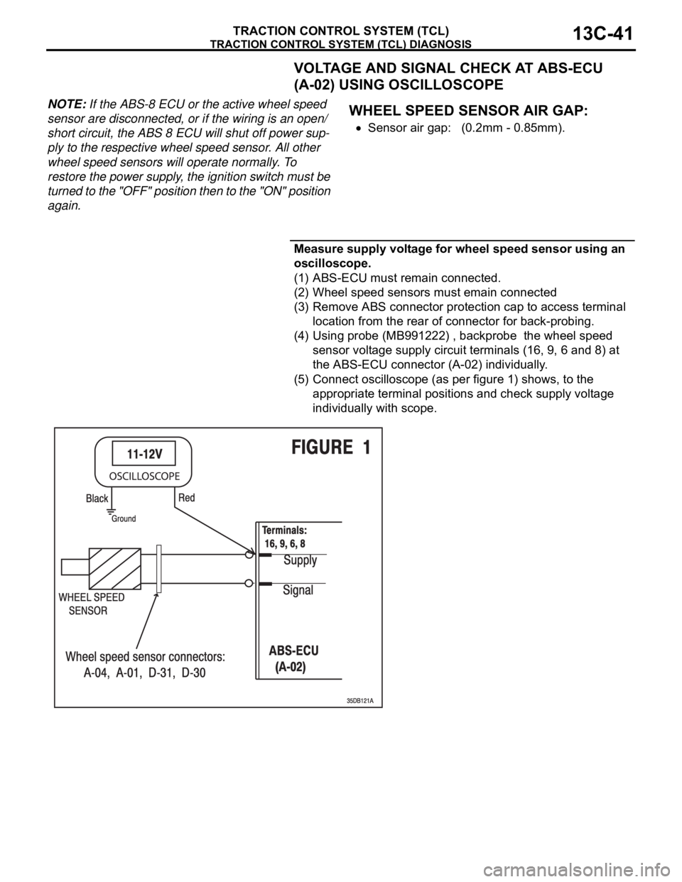
VOLTAGE AND SIGNAL CHECK AT ABS-ECU
(A-02) USING OSCILLOSCOPE
NOTE: If the ABS-8 ECU or the active wheel speed
sensor are disconnected, or if the wiring is an open/
short circuit, the ABS 8 ECU will shut off power sup-
ply to the respective wheel speed sensor. All other
wheel speed sensors will operate normally. To
restore the power supply, the ignition switch must be
turned to the "OFF" position then to the "ON" position
again..
WHEEL SPEED SENSOR AIR GAP:
Sensor air gap: (0.2mm - 0.85mm).
.
Measure supply voltage for wheel speed sensor using an
oscilloscope.
(1) ABS-ECU must remain connected.
(2) Wheel speed sensors must emain connected
(3) Remove ABS connector protection cap to access terminal
location from the rear of connector for back-probing.
(4) Using probe (MB991222) , backprobe the wheel speed
sensor voltage supply circuit terminals (16, 9, 6 and 8) at
the ABS-ECU connector (A-02) individually.
(5) Connect oscilloscope (as per figure 1) shows, to the
appropriate terminal positions and check supply voltage
individually with scope.
Page 1321 of 1500
TRACTION CONTROL SYSTEM (TCL) DIAGNOSIS
TRACTION CONTROL SYSTEM (TCL)13C-42
Connect oscilloscope to FL sensor signal terminal (16)
at ABS-ECU (A-02)
Connect oscilloscope to FR sensor signal terminal (9) at
ABS-ECU (A-02)
Connect oscilloscope to RL sensor signal terminal (6) at
ABS-ECU (A-02)
Connect oscilloscope to RR sensor signal terminal (8) at
ABS-ECU (A-02)
(6) Turn the ignition switch to the "ON" position.
Page 1322 of 1500

TRACTION CONTROL SYSTEM (TCL) DIAGNOSIS
TRACTION CONTROL SYSTEM (TCL)13C-43
(7) The recommended Supply Voltage at terminals 16, 9, 6,
and 8 are:
Set value: 10.0Volts - 14.5Volts
Q: Is the supply voltage within the set value?
YES : Check wheel speed sensor signal at ABS-ECU using
an oscillopscope
NO :
Refer to Power supply systemP.35B-63
Refer to Motor supply systemP.35B-48
Refer to Valve relay systemP.35B-56
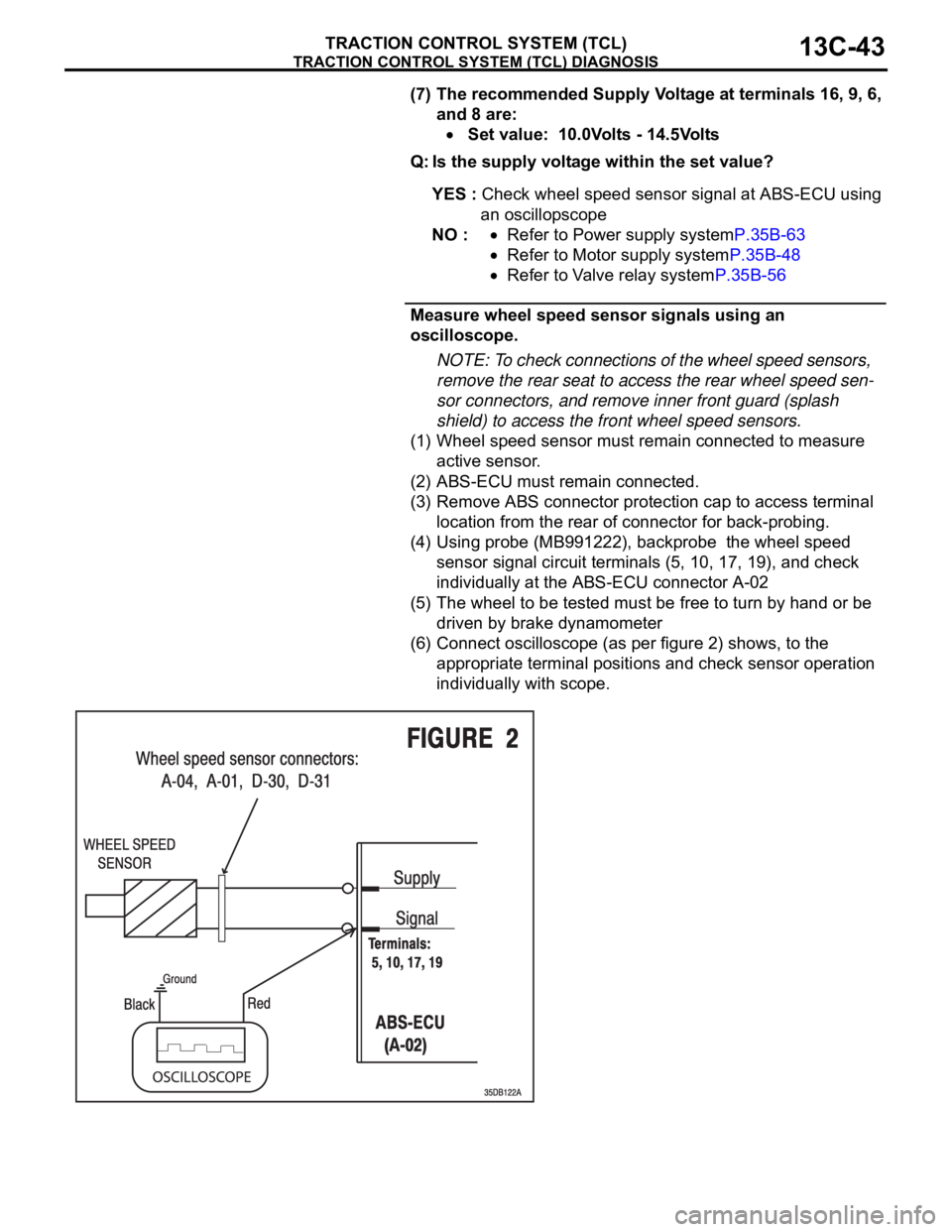
Measure wheel speed sensor signals using an
oscilloscope.
NOTE: To check connections of the wheel speed sensors,
remove the rear seat to access the rear wheel speed sen-
sor connectors, and remove inner front guard (splash
shield) to access the front wheel speed sensors.
(1) Wheel speed sensor must remain connected to measure
active sensor.
(2) ABS-ECU must remain connected.
(3) Remove ABS connector protection cap to access terminal
location from the rear of connector for back-probing.
(4) Using probe (MB991222), backprobe the wheel speed
sensor signal circuit terminals (5, 10, 17, 19), and check
individually at the ABS-ECU connector A-02
(5) The wheel to be tested must be free to turn by hand or be
driven by brake dynamometer
(6) Connect oscilloscope (as per figure 2) shows, to the
appropriate terminal positions and check sensor operation
individually with scope.
Page 1323 of 1500
TRACTION CONTROL SYSTEM (TCL) DIAGNOSIS
TRACTION CONTROL SYSTEM (TCL)13C-44
Connect oscilloscope to FL sensor signal terminal (5) at
ABS-ECU (A-02)
Connect oscilloscope to FR sensor signal terminal (10)
at ABS-ECU (A-02)
Connect oscilloscope to RL sensor signal terminal (17)
at ABS-ECU (A-02)
Connect oscilloscope to RR sensor signal terminal (19)
at ABS-ECU (A-02)
(7) Recommended Oscilloscope setting:
Y-axis: 2Volts
X-axis: 100ms
(8) Turn the ignition switch to the "ON" position.
(9) Turn wheel by hand at approximately 1 revolution per
second (r/sec) or drive on brake dynamometer at 5km/h.
The measurement reading of the active wheel speed sen-
sors on the oscilloscope should correspond to figure 3
below.
NOTE: If the oscilloscope signal shape is correct and wheel
sensor air gap is within specification, but the voltage values are
either higher or lower as shown in the table below, the wheel
speed sensor must be changed.
Page 1324 of 1500
SPECIAL TOOLS
TRACTION CONTROL SYSTEM (TCL)13C-45
SPECIAL TOOLSM1136000600024
TOOL TOOL NUMBER AND NAME SUPERSESSION APPLICATION
MB991958
A: MB991824
B: MB991827
C: MB991910
D: MB991911
E: MB991914
F: MB991825
G: MB991826
MUT-III sub assembly
A: Vehicle communication
interface (V.C.I.)
B: MUT-III USB cable
C: MUT-III main harness A
(Vehicles with CAN
communication system)
D: MUT-III main harness B
(Vehicles without CAN
communication system)
E: MUT-III main harness C
(for Daimler Chrysler
models only)
F: MUT-III measurement
adapter
G: MUT-III trigger harnessMB991824-KIT
NOTE: G: MB991826
MUT-III trigger
harness is not
necessary when
pushing V.C.I. ENTER
key.Checking diagnostic
trouble codes
For vehicles with CAN
communication, use
MUT-III main harness A
to send simulated
vehicle speed. If you
connect MUT-III main
harness B instead, the
CAN communication
does not function
correctly.
Page 1325 of 1500
SPECIAL TOOLS
TRACTION CONTROL SYSTEM (TCL)13C-46
MB991223
A: MB991219
B: MB991220
C: MB991221
D: MB991222
Harness set
A: Inspection harness
B: LED harness
C: LED harness adapter
D: ProbeGeneral service tools Checking the continuity
and measuring the
voltage at the harness
connector TOOL TOOL NUMBER AND NAME SUPERSESSION APPLICATION