2005 MERCEDES-BENZ SPRINTER wheel torque
[x] Cancel search: wheel torquePage 1022 of 1232
TORQUE CONVERTER CLUTCH (TCC)
In a standard torque converter, the impeller and
turbine are rotating at about the same speed and the
stator is freewheeling, providing no torque multipli-
cation. By applying the turbine's piston and friction
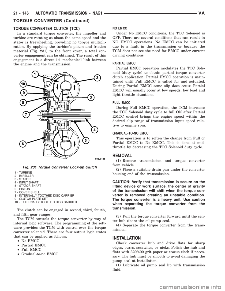
material (Fig. 231) to the front cover, a total con-
verter engagement can be obtained. The result of this
engagement is a direct 1:1 mechanical link between
the engine and the transmission.
The clutch can be engaged in second, third, fourth,
and fifth gear ranges.
The TCM controls the torque converter by way of
internal logic software. The programming of the soft-
ware provides the TCM with control over the torque
converter solenoid. There are four output logic states
that can be applied as follows:
²No EMCC
²Partial EMCC
²Full EMCC
²Gradual-to-no EMCCNO EMCC
Under No EMCC conditions, the TCC Solenoid is
OFF. There are several conditions that can result in
NO EMCC operations. No EMCC can be initiated
due to a fault in the transmission or because the
TCM does not see the need for EMCC under current
driving conditions.
PARTIAL EMCC
Partial EMCC operation modulates the TCC Sole-
noid (duty cycle) to obtain partial torque converter
clutch application. Partial EMCC operation is main-
tained until Full EMCC is called for and actuated.
During Partial EMCC some slip does occur. Partial
EMCC will usually occur at low speeds, low load and
light throttle situations.
FULL EMCC
During Full EMCC operation, the TCM increases
the TCC Solenoid duty cycle to full ON after Partial
EMCC control brings the engine speed within the
desired slip range of transmission input speed rela-
tive to engine rpm.
GRADUAL-TO-NO EMCC
This operation is to soften the change from Full or
Partial EMCC to No EMCC. This is done at mid-
throttle by decreasing the TCC Solenoid duty cycle.
REMOVAL
(1) Remove transmission and torque converter
from vehicle.
(2) Place a suitable drain pan under the converter
housing end of the transmission.
CAUTION: Verify that transmission is secure on the
lifting device or work surface, the center of gravity
of the transmission will shift when the torque con-
verter is removed creating an unstable condition.
The torque converter is a heavy unit. Use caution
when separating the torque converter from the
transmission.
(3) Pull the torque converter forward until the cen-
ter hub clears the oil pump seal.
(4) Separate the torque converter from the trans-
mission.
INSTALLATION
Check converter hub and drive flats for sharp
edges, burrs, scratches, or nicks. Polish the hub and
flats with 320/400 grit paper or crocus cloth if neces-
sary. The hub must be smooth to avoid damaging the
pump seal at installation.
(1) Lubricate oil pump seal lip with transmission
fluid.
Fig. 231 Torque Converter Lock-up Clutch
1 - TURBINE
2 - IMPELLER
3-STATOR
4 - INPUT SHAFT
5 - STATOR SHAFT
6 - PISTON
7 - COVER SHELL
8 - INTERNALLY TOOTHED DISC CARRIER
9 - CLUTCH PLATE SET
10 - EXTERNALLY TOOTHED DISC CARRIER
21 - 146 AUTOMATIC TRANSMISSION - NAG1VA
TORQUE CONVERTER (Continued)
Page 1025 of 1232
TIRES/WHEELS
TABLE OF CONTENTS
page page
TIRES/WHEELS
DIAGNOSIS AND TESTING - TIRE AND
WHEEL RUNOUT......................1
STANDARD PROCEDURE
STANDARD PROCEDURE - MATCH
MOUNTING...........................2
STANDARD PROCEDURE - TIRE AND
WHEEL BALANCE......................3
STANDARD PROCEDURE - TIRE ROTATION . 5
SPECIFICATIONS
TORQUE CHART......................5
TIRES
DESCRIPTION
DESCRIPTION - TIRES..................6
DESCRIPTION - RADIAL ± PLY TIRES......6
DESCRIPTION - TIRE PRESSURE FOR
HIGH SPEEDS.........................6
DESCRIPTION - REPLACEMENT TIRES.....7
DESCRIPTION - TIRE INFLATION
PRESSURES..........................7
DIAGNOSIS AND TESTING
DIAGNOSIS AND TESTING - PRESSURE
GAUGES.............................8
DIAGNOSIS AND TESTING - TIRE NOISE
OR VIBRATION........................8
DIAGNOSIS AND TESTING - TREAD WEAR
INDICATORS..........................8DIAGNOSIS AND TESTING - TIRE WEAR
PATTERNS...........................8
DIAGNOSIS AND TESTING - TIRE/VEHICLE
LEAD................................8
STANDARD PROCEDURE - REPAIRING
LEAKS..............................10
CLEANING............................10
SPECIFICATIONS
TIRES..............................10
SPARE TIRE CARRIER
REMOVAL.............................10
INSTALLATION.........................10
WHEELS
DESCRIPTION.........................11
OPERATION...........................11
DIAGNOSIS AND TESTING
WHEEL INSPECTION..................11
STANDARD PROCEDURE
STANDARD PROCEDURE - WHEEL
REPLACEMENT.......................11
STANDARD PROCEDURE - DUAL REAR
WHEEL INSTALLATION.................12
REMOVAL.............................13
INSTALLATION.........................13
TIRES/WHEELS
DIAGNOSIS AND TESTING - TIRE AND WHEEL
RUNOUT
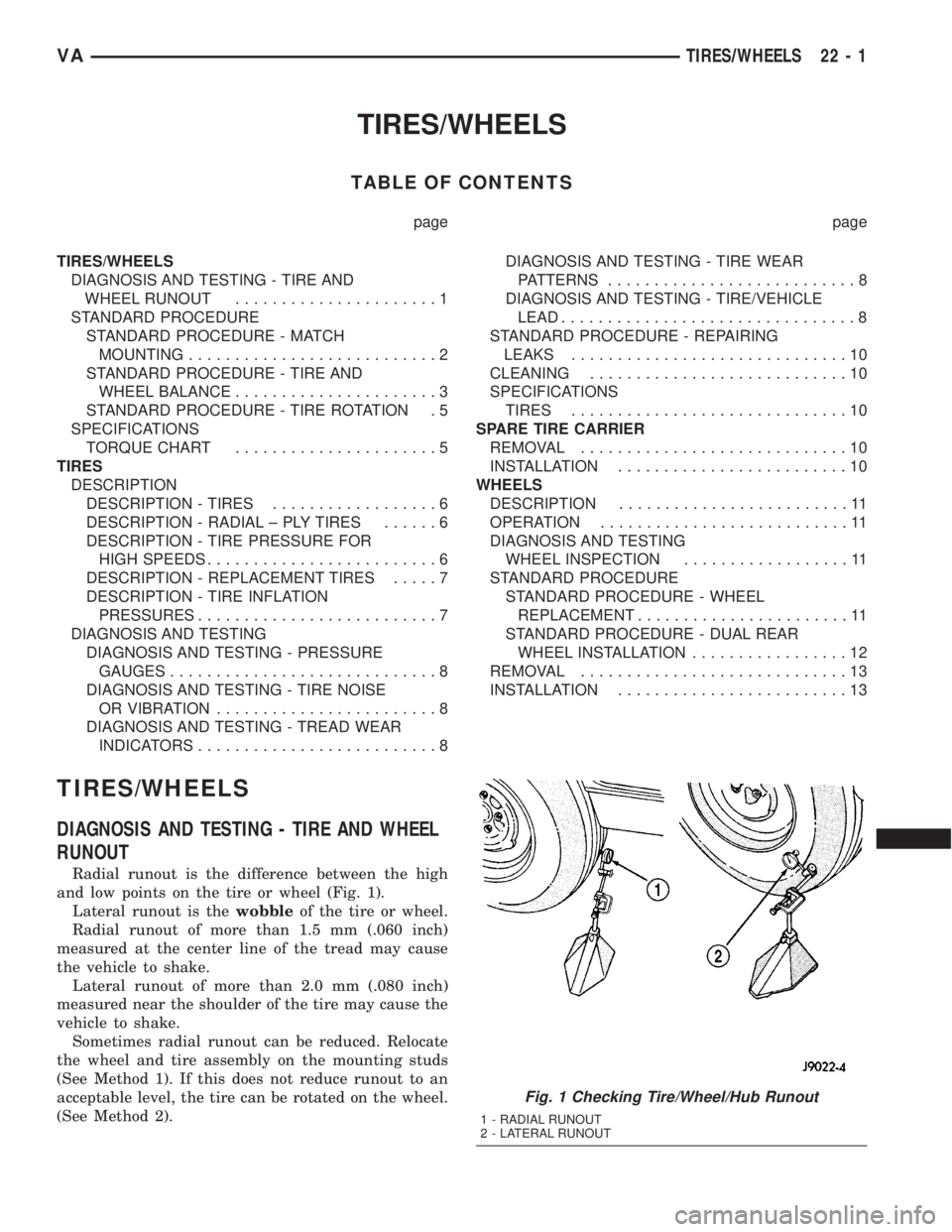
Radial runout is the difference between the high
and low points on the tire or wheel (Fig. 1).
Lateral runout is thewobbleof the tire or wheel.
Radial runout of more than 1.5 mm (.060 inch)
measured at the center line of the tread may cause
the vehicle to shake.
Lateral runout of more than 2.0 mm (.080 inch)
measured near the shoulder of the tire may cause the
vehicle to shake.
Sometimes radial runout can be reduced. Relocate
the wheel and tire assembly on the mounting studs
(See Method 1). If this does not reduce runout to an
acceptable level, the tire can be rotated on the wheel.
(See Method 2).
Fig. 1 Checking Tire/Wheel/Hub Runout
1 - RADIAL RUNOUT
2 - LATERAL RUNOUT
VATIRES/WHEELS 22 - 1
Page 1026 of 1232
METHOD 1 (RELOCATE WHEEL ON HUB)
(1) Drive vehicle a short distance to eliminate tire
flat spotting from a parked position.
(2) Check wheel bearings and adjust if adjustable
or replace if necessary.
(3) Check the wheel mounting surface.
(4) Relocate wheel on the mounting, two studs
over from the original position.
(5) Tighten wheel nuts until all are properly
torqued, to eliminate brake distortion.
(6) Check radial runout. If still excessive, mark
tire sidewall, wheel, and stud at point of maximum
runout and proceed to Method 2.
METHOD 2 (RELOCATE TIRE ON WHEEL)
NOTE: Rotating the tire on wheel is particularly
effective when there is runout in both tire and
wheel.
(1) Remove tire from wheel and mount wheel on
service dynamic balance machine.
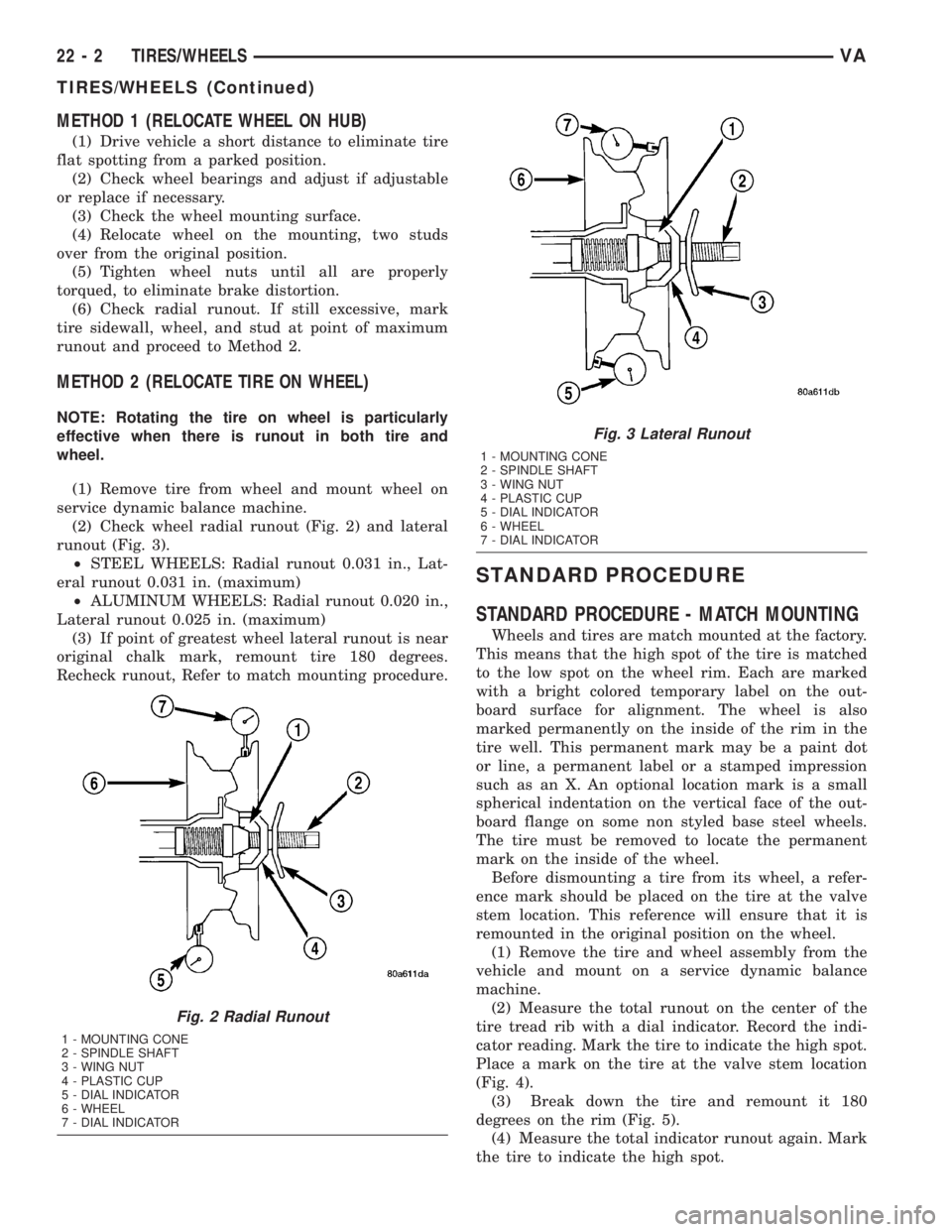
(2) Check wheel radial runout (Fig. 2) and lateral
runout (Fig. 3).
²STEEL WHEELS: Radial runout 0.031 in., Lat-
eral runout 0.031 in. (maximum)
²ALUMINUM WHEELS: Radial runout 0.020 in.,
Lateral runout 0.025 in. (maximum)
(3) If point of greatest wheel lateral runout is near
original chalk mark, remount tire 180 degrees.
Recheck runout, Refer to match mounting procedure.
STANDARD PROCEDURE
STANDARD PROCEDURE - MATCH MOUNTING
Wheels and tires are match mounted at the factory.
This means that the high spot of the tire is matched
to the low spot on the wheel rim. Each are marked
with a bright colored temporary label on the out-
board surface for alignment. The wheel is also
marked permanently on the inside of the rim in the
tire well. This permanent mark may be a paint dot
or line, a permanent label or a stamped impression
such as an X. An optional location mark is a small
spherical indentation on the vertical face of the out-
board flange on some non styled base steel wheels.
The tire must be removed to locate the permanent
mark on the inside of the wheel.
Before dismounting a tire from its wheel, a refer-
ence mark should be placed on the tire at the valve
stem location. This reference will ensure that it is
remounted in the original position on the wheel.
(1) Remove the tire and wheel assembly from the
vehicle and mount on a service dynamic balance
machine.
(2) Measure the total runout on the center of the
tire tread rib with a dial indicator. Record the indi-
cator reading. Mark the tire to indicate the high spot.
Place a mark on the tire at the valve stem location
(Fig. 4).
(3) Break down the tire and remount it 180
degrees on the rim (Fig. 5).
(4) Measure the total indicator runout again. Mark
the tire to indicate the high spot.
Fig. 2 Radial Runout
1 - MOUNTING CONE
2 - SPINDLE SHAFT
3 - WING NUT
4 - PLASTIC CUP
5 - DIAL INDICATOR
6 - WHEEL
7 - DIAL INDICATOR
Fig. 3 Lateral Runout
1 - MOUNTING CONE
2 - SPINDLE SHAFT
3 - WING NUT
4 - PLASTIC CUP
5 - DIAL INDICATOR
6 - WHEEL
7 - DIAL INDICATOR
22 - 2 TIRES/WHEELSVA
TIRES/WHEELS (Continued)
Page 1029 of 1232
STANDARD PROCEDURE - TIRE ROTATION
Tires on the front and rear axles operate at differ-
ent loads and perform different steering, driving, and
braking functions. For these reasons, the tires wear
at unequal rates. They may also develop irregular
wear patterns. These effects can be reduced by rotat-
ing the tires according to the maintenance schedule
in the Owners Manual. This will improve tread life,
traction and maintain a smooth quiet ride.
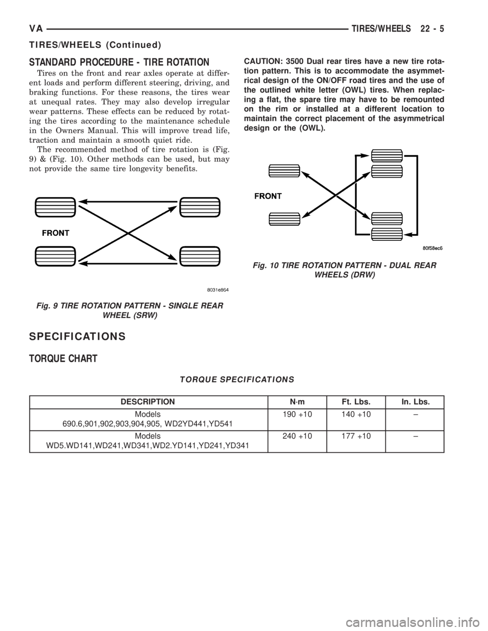
The recommended method of tire rotation is (Fig.
9) & (Fig. 10). Other methods can be used, but may
not provide the same tire longevity benefits.CAUTION: 3500 Dual rear tires have a new tire rota-
tion pattern. This is to accommodate the asymmet-
rical design of the ON/OFF road tires and the use of
the outlined white letter (OWL) tires. When replac-
ing a flat, the spare tire may have to be remounted
on the rim or installed at a different location to
maintain the correct placement of the asymmetrical
design or the (OWL).
SPECIFICATIONS
TORQUE CHART
TORQUE SPECIFICATIONS
DESCRIPTION N´m Ft. Lbs. In. Lbs.
Models
690.6,901,902,903,904,905, WD2YD441,YD541190 +10 140 +10 ±
Models
WD5.WD141,WD241,WD341,WD2.YD141,YD241,YD341240 +10 177 +10 ±
Fig. 9 TIRE ROTATION PATTERN - SINGLE REAR
WHEEL (SRW)
Fig. 10 TIRE ROTATION PATTERN - DUAL REAR
WHEELS (DRW)
VATIRES/WHEELS 22 - 5
TIRES/WHEELS (Continued)
Page 1034 of 1232
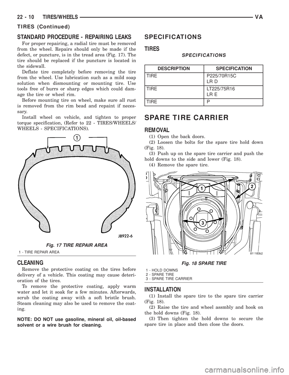
STANDARD PROCEDURE - REPAIRING LEAKS
For proper repairing, a radial tire must be removed
from the wheel. Repairs should only be made if the
defect, or puncture, is in the tread area (Fig. 17). The
tire should be replaced if the puncture is located in
the sidewall.
Deflate tire completely before removing the tire
from the wheel. Use lubrication such as a mild soap
solution when dismounting or mounting tire. Use
tools free of burrs or sharp edges which could dam-
age the tire or wheel rim.
Before mounting tire on wheel, make sure all rust
is removed from the rim bead and repaint if neces-
sary.
Install wheel on vehicle, and tighten to proper
torque specification, (Refer to 22 - TIRES/WHEELS/
WHEELS - SPECIFICATIONS).
CLEANING
Remove the protective coating on the tires before
delivery of a vehicle. This coating may cause deteri-
oration of the tires.
To remove the protective coating, apply warm
water and let it soak for a few minutes. Afterwards,
scrub the coating away with a soft bristle brush.
Steam cleaning may also be used to remove the coat-
ing.
NOTE: DO NOT use gasoline, mineral oil, oil-based
solvent or a wire brush for cleaning.
SPECIFICATIONS
TIRES
SPECIFICATIONS
DESCRIPTION SPECIFICATION
TIRE P225/70R15C
LR D
TIRE LT225/75R16
LR E
TIRE P
SPARE TIRE CARRIER
REMOVAL
(1) Open the back doors.
(2) Loosen the bolts for the spare tire hold down
(Fig. 18).
(3) Push up on the spare tire carrier and push the
hold downs to the side and lower (Fig. 18).
(4) Remove the spare tire.
INSTALLATION
(1) Install the spare tire to the spare tire carrier
(Fig. 18).
(2) Raise the tire and wheel assmbly and hook on
the hold downs (Fig. 18).
(3) Then tighten the hold downs to secure the
spare tire in place and then close the doors.
Fig. 17 TIRE REPAIR AREA
1 - TIRE REPAIR AREA
Fig. 18 SPARE TIRE
1 - HOLD DOWNS
2 - SPARE TIRE
3 - SPARE TIRE CARRIER
22 - 10 TIRES/WHEELSVA
TIRES (Continued)
Page 1035 of 1232
WHEELS
DESCRIPTION
Original equipment wheels are designed for the
specified Maximum Vehicle Capacity.
All models use steel or aluminum wheels.
Aluminum wheels require special balance weights
and alignment equipment.
(1) On vehicles equipped with dual rear wheels,
The slots in the wheel must be aligned to provide
access to the valve stem.
OPERATION
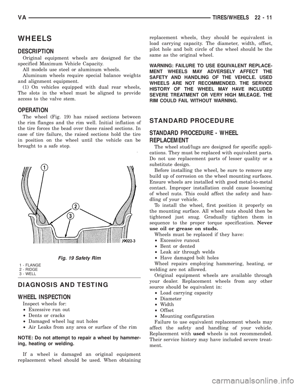
The wheel (Fig. 19) has raised sections between
the rim flanges and the rim well. Initial inflation of
the tire forces the bead over these raised sections. In
case of tire failure, the raised sections hold the tire
in position on the wheel until the vehicle can be
brought to a safe stop.
DIAGNOSIS AND TESTING
WHEEL INSPECTION
Inspect wheels for:
²Excessive run out
²Dents or cracks
²Damaged wheel lug nut holes
²Air Leaks from any area or surface of the rim
NOTE: Do not attempt to repair a wheel by hammer-
ing, heating or welding.
If a wheel is damaged an original equipment
replacement wheel should be used. When obtainingreplacement wheels, they should be equivalent in
load carrying capacity. The diameter, width, offset,
pilot hole and bolt circle of the wheel should be the
same as the original wheel.
WARNING: FAILURE TO USE EQUIVALENT REPLACE-
MENT WHEELS MAY ADVERSELY AFFECT THE
SAFETY AND HANDLING OF THE VEHICLE. USED
WHEELS ARE NOT RECOMMENDED. THE SERVICE
HISTORY OF THE WHEEL MAY HAVE INCLUDED
SEVERE TREATMENT OR VERY HIGH MILEAGE. THE
RIM COULD FAIL WITHOUT WARNING.
STANDARD PROCEDURE
STANDARD PROCEDURE - WHEEL
REPLACEMENT
The wheel stud/lugs are designed for specific appli-
cations. They must be replaced with equivalent parts.
Do not use replacement parts of lesser quality or a
substitute design.
Before installing the wheel, be sure to remove any
build up of corrosion on the wheel mounting surfaces.
Ensure wheels are installed with good metal-to-metal
contact. Improper installation could cause loosening
of wheel nuts. This could affect the safety and han-
dling of your vehicle.
To install the wheel, first position it properly on
the mounting surface. All wheel nuts should then be
tightened just snug. Gradually tighten them in
sequence to the proper torque specification.Never
use oil or grease on studs.
Wheels must be replaced if they have:
²Excessive runout
²Bent or dented
²Leak air through welds
²Have damaged bolt holes
Wheel repairs employing hammering, heating, or
welding are not allowed.
Original equipment wheels are available through
your dealer. Replacement wheels from any other
source should be equivalent in:
²Load carrying capacity
²Diameter
²Width
²Offset
²Mounting configuration
Failure to use equivalent replacement wheels may
affect the safety and handling of your vehicle.
Replacement withusedwheels is not recommended.
Their service history may have included severe treat-
ment.
Fig. 19 Safety Rim
1 - FLANGE
2 - RIDGE
3 - WELL
VATIRES/WHEELS 22 - 11
Page 1036 of 1232
STANDARD PROCEDURE - DUAL REAR WHEEL
INSTALLATION
The tires on both wheels must be completely raised
off the ground when tightening the lug nuts. This
will ensure correct wheel centering and maximum
wheel clamping.
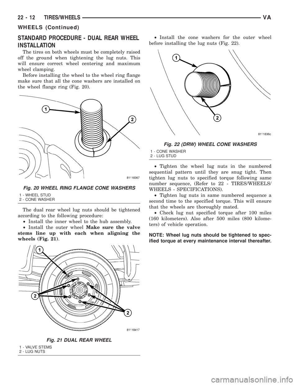
Before installing the wheel to the wheel ring flange
make sure that all the cone washers are installed on
the wheel flange ring (Fig. 20).
The dual rear wheel lug nuts should be tightened
according to the following procedure:
²Install the inner wheel to the hub assembly.
²Install the outer wheelMake sure the valve
stems line up with each when aligning the
wheels (Fig. 21).²Install the cone washers for the outer wheel
before installing the lug nuts (Fig. 22).
²Tighten the wheel lug nuts in the numbered
sequential pattern until they are snug tight. Then
tighten lug nuts to specified torque following same
number sequence, (Refer to 22 - TIRES/WHEELS/
WHEELS - SPECIFICATIONS).
²Tighten lug nuts in same numbered sequence a
second time to the specified torque. This will ensure
that the wheels are thoroughly mated.
²Check lug nut specified torque after 100 miles
(160 kilometers). Also after 500 miles (800 kilome-
ters) of vehicle operation.
NOTE: Wheel lug nuts should be tightened to spec-
ified torque at every maintenance interval thereafter.
Fig. 20 WHEEL RING FLANGE CONE WASHERS
1 - WHEEL STUD
2 - CONE WASHER
Fig. 21 DUAL REAR WHEEL
1 - VALVE STEMS
2 - LUG NUTS
Fig. 22 (DRW) WHEEL CONE WASHERS
1 - CONE WASHER
2 - LUG STUD
22 - 12 TIRES/WHEELSVA
WHEELS (Continued)
Page 1214 of 1232
CIRCUIT BREAKER - OPERATION......8W-97-2
CIRCUIT INFORMATION - DESCRIPTION . 8W-01-5
CLAMP PLATES - INSTALLATION,
SPRING..............................2-8
CLAMP PLATES - REMOVAL, SPRING......2-8
CLASSIFICATION - STANDARD
PROCEDURE, INJECTOR...............14-22
CLEARANCE LAMP BULB -
INSTALLATION........................8L-8
CLEARANCE LAMP BULB - REMOVAL.....8L-8
CLEARANCE LAMP UNIT -
INSTALLATION........................8L-9
CLEARANCE LAMP UNIT - REMOVAL......8L-8
CLOCK - DESCRIPTION................8J-13
CLOCK - OPERATION..................8J-14
CLOCKSPRING - DESCRIPTION.........8O-12
CLOCKSPRING - INSTALLATION.........8O-15
CLOCKSPRING - OPERATION...........8O-13
CLOCKSPRING - REMOVAL............8O-14
CLOCKSPRING CENTERING - STANDARD
PROCEDURE........................8O-13
CLOGGED INDICATOR - DESCRIPTION,
FUEL FILTER........................8J-15
CLOGGED INDICATOR - OPERATION,
FUEL FILTER........................8J-15
CLUSTER - DESCRIPTION, INSTRUMENT . . . 8J-2
CLUSTER - DIAGNOSIS AND TESTING,
INSTRUMENT........................8J-7
CLUSTER - INSTALLATION, INSTRUMENT . . 8J-9
CLUSTER - INSTALLATION, TOP COVER . . . 23-62
CLUSTER - OPERATION, INSTRUMENT.....8J-5
CLUSTER - REMOVAL, INSTRUMENT......8J-7
CLUSTER - REMOVAL, TOP COVER......23-62
CLUSTER BEZEL - INSTALLATION........23-54
CLUSTER BEZEL - REMOVAL...........23-53
CLUTCH - ASSEMBLY, FREEWHEELING . . 21-107
CLUTCH - DESCRIPTION, A/C
COMPRESSOR........................24-8
CLUTCH - DESCRIPTION,
FREEWHEELING.....................21-105
CLUTCH - DISASSEMBLY,
FREEWHEELING.....................21-106
CLUTCH - INSTALLATION, FAN DRIVE
VISCOUS............................7-16
CLUTCH - OPERATION, A/C
COMPRESSOR........................24-8
CLUTCH - OPERATION, FREEWHEELING . . 21-105
CLUTCH - REMOVAL, FAN DRIVE
VISCOUS............................7-16
CLUTCH AIR GAP - STANDARD
PROCEDURE, COMPRESSOR............24-9
CLUTCH B1 - ASSEMBLY, HOLDING.....21-113
CLUTCH B1 - DISASSEMBLY, HOLDING . . 21-112
CLUTCH B2 - ASSEMBLY, HOLDING.....21-116
CLUTCH B2 - DISASSEMBLY, HOLDING . . 21-115
CLUTCH BREAK-IN - STANDARD
PROCEDURE, COMPRESSOR............24-9
CLUTCH COIL - DIAGNOSIS AND
TESTING, COMPRESSOR...............24-12
CLUTCH K1 - ASSEMBLY, DRIVING.......21-75
CLUTCH K1 - DISASSEMBLY, DRIVING....21-74
CLUTCH K2 - ASSEMBLY, DRIVING.......21-78
CLUTCH K2 - DISASSEMBLY, DRIVING....21-76
CLUTCH K3 - ASSEMBLY, DRIVING.......21-80
CLUTCH K3 - DISASSEMBLY, DRIVING....21-80
CLUTCH/COIL - INSPECTION,
COMPRESSOR.......................24-10
CLUTCHES - DESCRIPTION, DRIVING.....21-72
CLUTCHES - DESCRIPTION, HOLDING . . . 21-111
CLUTCHES - OPERATION, DRIVING......21-72
CLUTCHES - OPERATION, HOLDING.....21-112
CODES - SPECIFICATIONS, PAINT........23-74
COIL - DIAGNOSIS AND TESTING,
COMPRESSOR CLUTCH...............24-12
COLUMN OPENING COVER -
INSTALLATION, STEERING.............23-66
COLUMN OPENING COVER - REMOVAL,
STEERING..........................23-66
COMPRESSION TESTING ENGINE -
STANDARD PROCEDURE.................9-3
COMPRESSOR - DESCRIPTION, A/C......24-49
COMPRESSOR - INSTALLATION, A/C
.....24-51
COMPRESSOR - OPERATION, A/C
........24-49
COMPRESSOR - REMOVAL, A/C
.........24-50
COMPRESSOR CLUTCH - DESCRIPTION,
A/C
................................24-8
COMPRESSOR CLUTCH - OPERATION,
A/C
................................24-8COMPRESSOR CLUTCH AIR GAP -
STANDARD PROCEDURE................24-9
COMPRESSOR CLUTCH BREAK-IN -
STANDARD PROCEDURE................24-9
COMPRESSOR CLUTCH COIL -
DIAGNOSIS AND TESTING.............24-12
COMPRESSOR CLUTCH/COIL -
INSPECTION........................24-10
COMPRESSOR NOISE - DIAGNOSIS AND
TESTING...........................24-49
CONDENSER - DESCRIPTION, A/C.......24-52
CONDENSER - INSTALLATION, A/C.......24-52
CONDENSER - OPERATION, A/C.........24-52
CONDENSER - REMOVAL, A/C..........24-52
CONDITIONER - DESCRIPTION, HEATER
AND AIR ............................24-1
CONDITIONER - OPERATION, HEATER
AND AIR ............................24-2
CONNECTING FUEL LINES - STANDARD
PROCEDURE, DISCONNECTING...........14-2
CONNECTING ROD - DESCRIPTION,
PISTON.............................9-40
CONNECTING RODS - STANDARD
PROCEDURE, CHECKING AND
REPAIRING..........................9-40
CONNECTOR - INSTALLATION........8W-01-9
CONNECTOR - REMOVAL............8W-01-8
CONNECTOR, GROUND AND SPLICE
INFORMATION - DESCRIPTION........8W-01-5
CONNECTOR/GROUND/SPLICE LOCATION
- DESCRIPTION....................8W-91-1
CONTACT - DESCRIPTION, PARK/
NEUTRAL..........................21-139
CONTACT - OPERATION, PARK/NEUTRAL . 21-140
CONTAMINATION - DIAGNOSIS AND
TESTING, BRAKE FLUID................5-14
CONTAMINATION - DIAGNOSIS AND
TESTING, FLUID....................21-102
CONTINUITY - STANDARD PROCEDURE,
TESTING.........................8W-01-8
CONTROL ARM - INSTALLATION, LOWER . . . 2-6
CONTROL ARM - REMOVAL, LOWER.......2-6
CONTROL INDICATOR - DESCRIPTION,
TRACTION..........................8J-24
CONTROL INDICATOR - OPERATION,
TRACTION..........................8J-24
CONTROL MALFUNCTION INDICATOR -
DESCRIPTION, TRACTION..............8J-25
CONTROL MALFUNCTION INDICATOR -
OPERATION, TRACTION................8J-25
CONTROL MODULE - DESCRIPTION......24-24
CONTROL MODULE - DESCRIPTION,
AIRBAG.............................8O-8
CONTROL MODULE - DESCRIPTION,
ENGINE.............................8E-3
CONTROL MODULE - DESCRIPTION,
TRANSMISSION.......................8E-5
CONTROL MODULE - DIAGNOSIS AND
TESTING...........................24-24
CONTROL MODULE - INSTALLATION.....24-25
CONTROL MODULE - INSTALLATION,
AIRBAG............................8O-11
CONTROL MODULE - INSTALLATION,
ENGINE.............................8E-4
CONTROL MODULE - OPERATION.......24-24
CONTROL MODULE - OPERATION,
AIRBAG.............................8O-9
CONTROL MODULE - OPERATION,
TRANSMISSION.......................8E-5
CONTROL MODULE - REMOVAL.........24-24
CONTROL MODULE - REMOVAL, AIRBAG . 8O-10
CONTROL MODULE - REMOVAL, ENGINE . . . 8E-4
CONTROLLER - INSTALLATION, ALB......5-15
CONTROLLER - REMOVAL, ALB..........5-15
CONTROLLER ANTILOCK BRAKE -
DESCRIPTION........................8E-3
CONTROLLER ANTILOCK BRAKE -
INSTALLATION........................8E-3
CONTROLLER ANTILOCK BRAKE -
REMOVAL...........................8E-3
CONVERTER - DESCRIPTION, TORQUE . . . 21-141
CONVERTER - INSTALLATION, CATALYTIC . . 11-3
CONVERTER - INSTALLATION, TORQUE
. . 21-146
CONVERTER - OPERATION, TORQUE
....21-143
CONVERTER - REMOVAL, CATALYTIC
......11-3
CONVERTER - REMOVAL, TORQUE
......21-146
CONVERTER HUB SEAL - INSTALLATION,
TORQUE
...........................21-147CONVERTER HUB SEAL - REMOVAL,
TORQUE...........................21-147
COOLANT - DESCRIPTION...............7-9
COOLANT - DESCRIPTION, ENGINE........0-1
COOLANT - DESCRIPTION, HOAT..........0-2
COOLANT - STANDARD PROCEDURE,
ADDING ADDITIONAL..................7-11
COOLANT LEVEL SENSOR -
INSTALLATION........................7-13
COOLANT LEVEL SENSOR - REMOVAL.....7-13
COOLANT LOW INDICATOR -
DESCRIPTION.......................8J-14
COOLANT LOW INDICATOR - OPERATION . 8J-14
COOLANT PUMP - DESCRIPTION,
ELECTRIC..........................24-57
COOLANT PUMP - INSTALLATION,
ELECTRIC..........................24-57
COOLANT PUMP - OPERATION,
ELECTRIC..........................24-57
COOLANT PUMP - REMOVAL, ELECTRIC . . 24-57
COOLANT TEMP SENSOR -
DESCRIPTION, ENGINE.................7-14
COOLANT TEMP SENSOR -
INSTALLATION, ENGINE................7-15
COOLANT TEMP SENSOR - REMOVAL,
ENGINE.............................7-14
COOLANT THERMOSTAT -
INSTALLATION, ENGINE................7-16
COOLANT THERMOSTAT - REMOVAL,
ENGINE.............................7-15
COOLER & LINES - INSTALLATION, OIL....9-50
COOLER & LINES - REMOVAL, OIL.......9-50
COOLER AND PLUMBING - CLEANING,
CHARGE AIR.........................11-5
COOLER AND PLUMBING -
DESCRIPTION, CHARGE AIR.............11-4
COOLER AND PLUMBING - INSPECTION,
CHARGE AIR.........................11-5
COOLER AND PLUMBING -
INSTALLATION, CHARGE AIR............11-5
COOLER AND PLUMBING - OPERATION,
CHARGE AIR.........................11-4
COOLER AND PLUMBING - REMOVAL,
CHARGE AIR.........................11-5
COOLER SYSTEM - LEAKS - DIAGNOSIS
AND TESTING, CHARGE AIR.............11-4
COOLER TUBE - INSTALLATION, FLUID . . . 19-14
COOLER TUBE - INSTALLATION, RETURN
HOSE FROM GEAR TO................19-15
COOLER TUBE - INSTALLATION, RETURN
LINE FROM PUMP TO.................19-15
COOLER TUBE - REMOVAL, FLUID.......19-14
COOLER TUBE - REMOVAL, RETURN
HOSE FROM GEAR TO................19-15
COOLER TUBE - REMOVAL, RETURN
LINE FROM PUMP TO.................19-15
COOLING SYSTEM - DIAGNOSIS AND
TESTING.............................7-2
COOLING SYSTEM - OPERATION..........7-1
COOLING SYSTEM - STANDARD
PROCEDURE, DRAINING................7-12
COOLING SYSTEM - STANDARD
PROCEDURE, REFILLING................7-12
COOLING SYSTEM LEAKS - DIAGNOSIS
AND TESTING........................7-10
COOLING SYSTEM REQUIREMENTS -
DESCRIPTION........................24-1
CORE - DESCRIPTION, HEATER.........24-57
CORE - INSTALLATION, HEATER.........24-58
CORE - OPERATION, HEATER...........24-57
CORE - REMOVAL, HEATER............24-58
CORE AND OIL GALLERY PLUGS -
STANDARD PROCEDURE, REPLACING
ENGINE.............................9-34
COVER - CLUSTER - INSTALLATION, TOP . 23-62
COVER - CLUSTER - REMOVAL, TOP.....23-62
COVER - INSTALLATION, CYLINDER
HEAD FRONT.........................9-26
COVER - INSTALLATION, ENGINE..........9-7
COVER - INSTALLATION, STEERING
COLUMN OPENING...................23-66
COVER - INSTALLATION, TIMING CHAIN
. . . 9-60
COVER - INSTALLATION, TOP
...........23-65
COVER - REMOVAL, CYLINDER HEAD
FRONT
..............................9-23
COVER - REMOVAL, ENGINE
..............9-4
COVER - REMOVAL, STEERING COLUMN
OPENING
...........................23-66
4 INDEXVA
Description Group-Page Description Group-Page Description Group-Page