2005 MERCEDES-BENZ SPRINTER coolant level
[x] Cancel search: coolant levelPage 838 of 1232
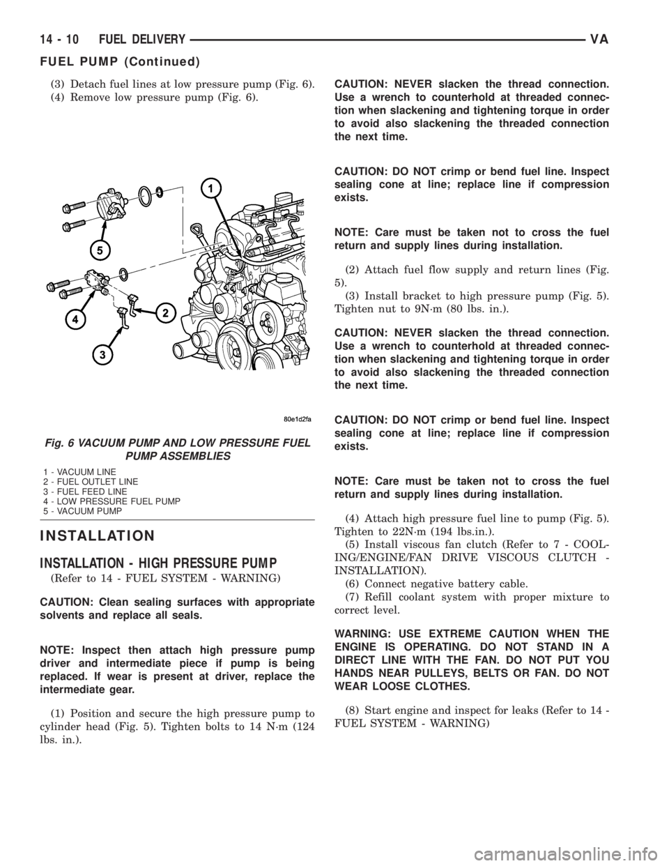
(3) Detach fuel lines at low pressure pump (Fig. 6).
(4) Remove low pressure pump (Fig. 6).
INSTALLATION
INSTALLATION - HIGH PRESSURE PUMP
(Refer to 14 - FUEL SYSTEM - WARNING)
CAUTION: Clean sealing surfaces with appropriate
solvents and replace all seals.
NOTE: Inspect then attach high pressure pump
driver and intermediate piece if pump is being
replaced. If wear is present at driver, replace the
intermediate gear.
(1) Position and secure the high pressure pump to
cylinder head (Fig. 5). Tighten bolts to 14 N´m (124
lbs. in.).CAUTION: NEVER slacken the thread connection.
Use a wrench to counterhold at threaded connec-
tion when slackening and tightening torque in order
to avoid also slackening the threaded connection
the next time.
CAUTION: DO NOT crimp or bend fuel line. Inspect
sealing cone at line; replace line if compression
exists.
NOTE: Care must be taken not to cross the fuel
return and supply lines during installation.
(2) Attach fuel flow supply and return lines (Fig.
5).
(3) Install bracket to high pressure pump (Fig. 5).
Tighten nut to 9N´m (80 lbs. in.).
CAUTION: NEVER slacken the thread connection.
Use a wrench to counterhold at threaded connec-
tion when slackening and tightening torque in order
to avoid also slackening the threaded connection
the next time.
CAUTION: DO NOT crimp or bend fuel line. Inspect
sealing cone at line; replace line if compression
exists.
NOTE: Care must be taken not to cross the fuel
return and supply lines during installation.
(4) Attach high pressure fuel line to pump (Fig. 5).
Tighten to 22N´m (194 lbs.in.).
(5) Install viscous fan clutch (Refer to 7 - COOL-
ING/ENGINE/FAN DRIVE VISCOUS CLUTCH -
INSTALLATION).
(6) Connect negative battery cable.
(7) Refill coolant system with proper mixture to
correct level.
WARNING: USE EXTREME CAUTION WHEN THE
ENGINE IS OPERATING. DO NOT STAND IN A
DIRECT LINE WITH THE FAN. DO NOT PUT YOU
HANDS NEAR PULLEYS, BELTS OR FAN. DO NOT
WEAR LOOSE CLOTHES.
(8) Start engine and inspect for leaks (Refer to 14 -
FUEL SYSTEM - WARNING)
Fig. 6 VACUUM PUMP AND LOW PRESSURE FUEL
PUMP ASSEMBLIES
1 - VACUUM LINE
2 - FUEL OUTLET LINE
3 - FUEL FEED LINE
4 - LOW PRESSURE FUEL PUMP
5 - VACUUM PUMP
14 - 10 FUEL DELIVERYVA
FUEL PUMP (Continued)
Page 853 of 1232
(15) Install battery tray(Refer to 8 - ELECTRI-
CAL/BATTERY SYSTEM/TRAY - INSTALLATION).
(16) Connect PDC to battery tray.
(17) Install battery (Refer to 8 - ELECTRICAL/
BATTERY SYSTEM/BATTERY - INSTALLATION).
(18) Connect steering coupler at gear box (RHD
Only).
(19) Install turbocharger to right engine mount
bracket (Refer to 11 - EXHAUST SYSTEM/TURBO-
CHARGER SYSTEM - INSTALLATION).
(20) Install charge air cooler to turbocharger inlet
adaptor (Refer to 11 - EXHAUST SYSTEM/CHARGE
AIR COOLER AND PLUMBING - INSTALLATION) .
(21) Install charger air cooler inlet hose (Refer to
11 - EXHAUST SYSTEM/CHARGE AIR COOLER
AND PLUMBING - INSTALLATION).
(22) Install air cleaner box assembly and hoses.
(23) Install upper radiator hose.
(24) Raise vehicle.
(25) Install dipstick tube into oil pan and tighten
retaining bolt.
(26) Install turbocharger down pipe assembly.
(27) Close cooling system drain.
(28) Install lower radiator deflector plate.
(29) Lower vehicle.
(30) Connect negative battery cable.
(31) Install engine cover (Refer to 9 - ENGINE -
INSTALLATION)..
(32) Fill cooling system with the correct mixture to
the proper level (Refer to 7 - COOLING/ENGINE/
COOLANT - STANDARD PROCEDURE).
WARNING: USE EXTREME CAUTION WHEN THE
ENGINE IS OPERATING. DO NOT PUT YOUR
HANDS NEAR PULLEYS, BELTS OR FAN. DO NOT
WEAR LOOSE CLOTHING.
(33) Start engine and inspect for leaks.
(34) Recharge air conditioning system.
FUEL PRESSURE SENSOR
DESCRIPTION
DESCRIPTION
The fuel pressure sensor provides the current low
pressure (the pressure that exist at the inlet of the
high pressure injection pump) fuel pressure to the
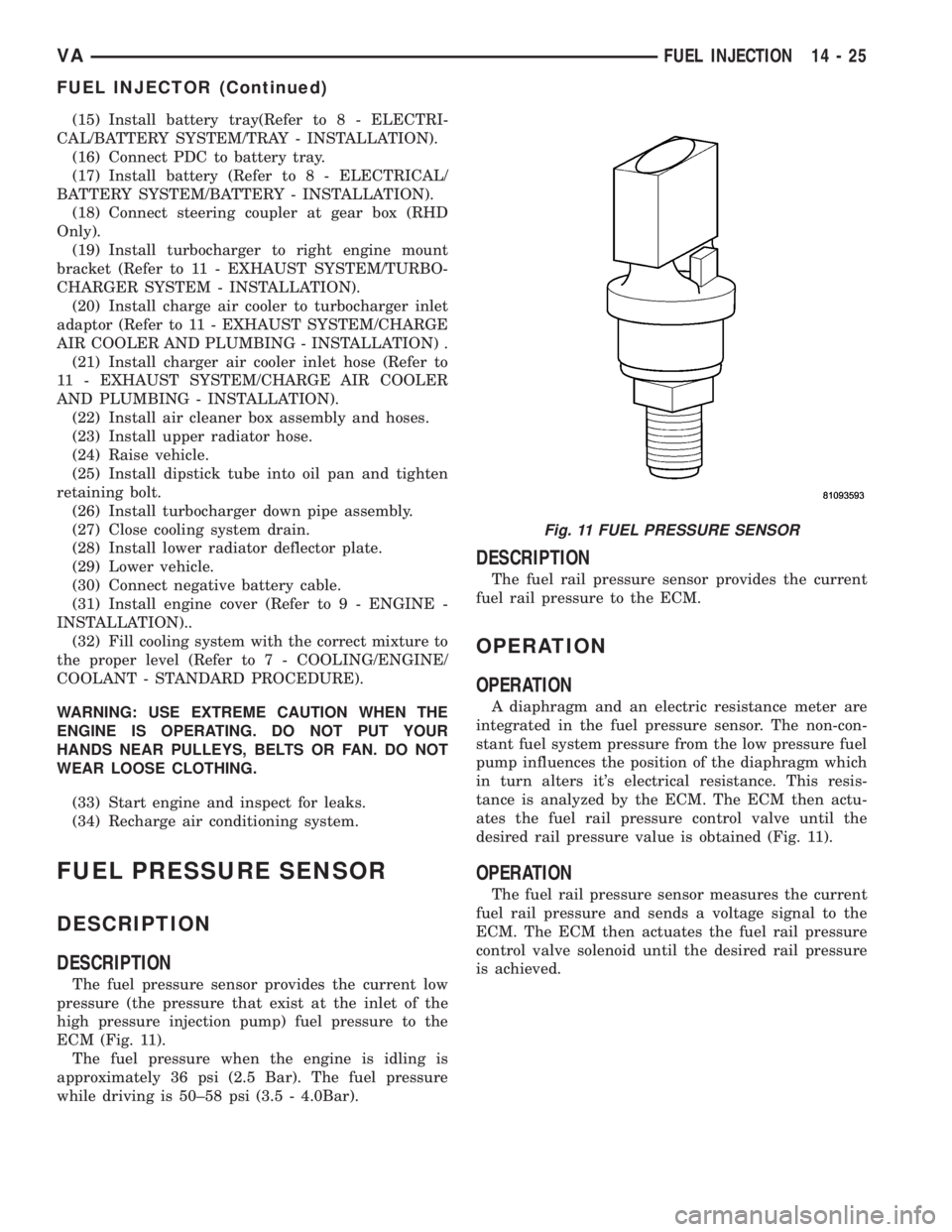
ECM (Fig. 11).
The fuel pressure when the engine is idling is
approximately 36 psi (2.5 Bar). The fuel pressure
while driving is 50±58 psi (3.5 - 4.0Bar).
DESCRIPTION
The fuel rail pressure sensor provides the current
fuel rail pressure to the ECM.
OPERATION
OPERATION
A diaphragm and an electric resistance meter are
integrated in the fuel pressure sensor. The non-con-
stant fuel system pressure from the low pressure fuel
pump influences the position of the diaphragm which
in turn alters it's electrical resistance. This resis-
tance is analyzed by the ECM. The ECM then actu-
ates the fuel rail pressure control valve until the
desired rail pressure value is obtained (Fig. 11).
OPERATION
The fuel rail pressure sensor measures the current
fuel rail pressure and sends a voltage signal to the
ECM. The ECM then actuates the fuel rail pressure
control valve solenoid until the desired rail pressure
is achieved.
Fig. 11 FUEL PRESSURE SENSOR
VAFUEL INJECTION 14 - 25
FUEL INJECTOR (Continued)
Page 978 of 1232
DIAGNOSIS AND TESTING
DIAGNOSIS AND TESTING - EFFECTS OF
INCORRECT FLUID LEVEL
A low fluid level allows the pump to take in air
along with the fluid. Air in the fluid will cause fluid
pressures to be low and develop slower than normal.
If the transmission is overfilled, the gears churn the
fluid into foam. This aerates the fluid and causing
the same conditions occurring with a low level. In
either case, air bubbles cause fluid overheating, oxi-
dation and varnish buildup which interferes with
valve and clutch operation. Foaming also causes fluid
expansion which can result in fluid overflow from the
transmission vent or fill tube. Fluid overflow can eas-
ily be mistaken for a leak if inspection is not careful.
DIAGNOSIS AND TESTING - CAUSES OF
BURNT FLUID
Burnt, discolored fluid is a result of overheating
which has three primary causes.
(1) Internal clutch slippage, usually caused by low
line pressure, inadequate clutch apply pressure, or
clutch seal failure.
(2) A result of restricted fluid flow through the
main and/or auxiliary cooler. This condition is usu-
ally the result of a faulty or improperly installed
drainback valve, a damaged main cooler, or severe
restrictions in the coolers and lines caused by debris
or kinked lines.
(3) Heavy duty operation with a vehicle not prop-
erly equipped for this type of operation. Trailer tow-
ing or similar high load operation will overheat the
transmission fluid if the vehicle is improperly
equipped. Such vehicles should have an auxiliary
transmission fluid cooler, a heavy duty cooling sys-
tem, and the engine/axle ratio combination needed to
handle heavy loads.
DIAGNOSIS AND TESTING - FLUID
CONTAMINATION
Transmission fluid contamination is generally a
result of:
²adding incorrect fluid
²failure to clean dipstick and fill tube when
checking level
²engine coolant entering the fluid
²internal failure that generates debris
²overheat that generates sludge (fluid break-
down)
²failure to replace contaminated converter after
repair
The use of non-recommended fluids can result in
transmission failure. The usual results are erratic
shifts, slippage, abnormal wear and eventual failuredue to fluid breakdown and sludge formation. Avoid
this condition by using recommended fluids only.
The dipstick cap and fill tube should be wiped
clean before checking fluid level. Dirt, grease and
other foreign material on the cap and tube could fall
into the tube if not removed beforehand. Take the
time to wipe the cap and tube clean before withdraw-
ing the dipstick.
Engine coolant in the transmission fluid is gener-
ally caused by a cooler malfunction. The only remedy
is to replace the radiator as the cooler in the radiator
is not a serviceable part. If coolant has circulated
through the transmission, an overhaul is necessary.
The torque converter should be replaced whenever
a failure generates sludge and debris. This is neces-
sary because normal converter flushing procedures
will not remove all contaminants.
STANDARD PROCEDURE
STANDARD PROCEDURE - CHECK OIL LEVEL
(1) Verify that the vehicle is parked on a level sur-
face.
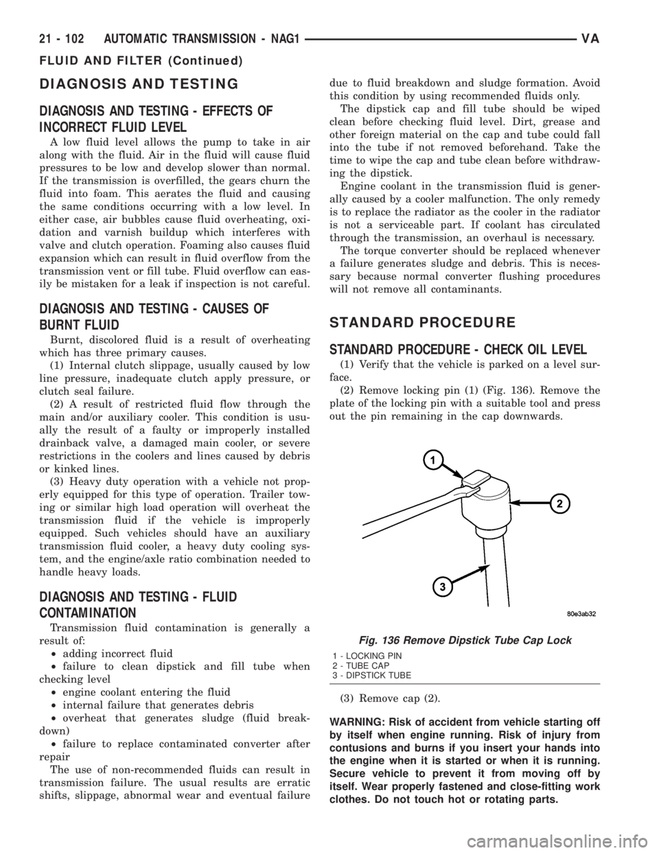
(2) Remove locking pin (1) (Fig. 136). Remove the
plate of the locking pin with a suitable tool and press
out the pin remaining in the cap downwards.
(3) Remove cap (2).
WARNING: Risk of accident from vehicle starting off
by itself when engine running. Risk of injury from
contusions and burns if you insert your hands into
the engine when it is started or when it is running.
Secure vehicle to prevent it from moving off by
itself. Wear properly fastened and close-fitting work
clothes. Do not touch hot or rotating parts.
Fig. 136 Remove Dipstick Tube Cap Lock
1 - LOCKING PIN
2 - TUBE CAP
3 - DIPSTICK TUBE
21 - 102 AUTOMATIC TRANSMISSION - NAG1VA
FLUID AND FILTER (Continued)
Page 1129 of 1232
HEATING & AIR CONDITIONING
TABLE OF CONTENTS
page page
HEATING & AIR CONDITIONING
DESCRIPTION
DESCRIPTION - COOLING SYSTEM
REQUIREMENTS.......................1
DESCRIPTION - HEATER AND AIR
CONDITIONER........................1
OPERATION - HEATER AND AIR
CONDITIONER........................2
DIAGNOSIS AND TESTING
DIAGNOSIS AND TESTING - FUNCTION
TEST................................3
DIAGNOSIS AND TESTING - A/C
PERFORMANCE TEST..................3DIAGNOSIS AND TESTING - HEATER
PERFORMANCE.......................4
SPECIFICATIONS
A/C SYSTEM..........................5
CONTROLS - FRONT......................8
CONTROLS - REAR......................22
DISTRIBUTION - FRONT...................31
DISTRIBUTION - REAR....................39
PLUMBING.............................43
CABIN HEATER.........................72
HEATING & AIR
CONDITIONING
DESCRIPTION
DESCRIPTION - COOLING SYSTEM
REQUIREMENTS
To maintain the performance level of the heating-
air conditioning system, the engine cooling system
must be properly maintained. The use of a bug
screen is not recommended. Any obstructions in front
of the radiator or condenser will reduce the perfor-
mance of the air conditioning and engine cooling sys-
tems.
The engine cooling system includes the radiator,
thermostat, heater core, heater hoses and the engine
coolant pump. Refer to Cooling for more information
before opening or attempting any service to the
engine cooling system.
DESCRIPTION - HEATER AND AIR
CONDITIONER
A automatic temperature control (ATC) single zone
type heating-air conditioning system is standard
equipment on this model. A manually controlled rear
air conditioning system is available as a factory-in-
stalled option.
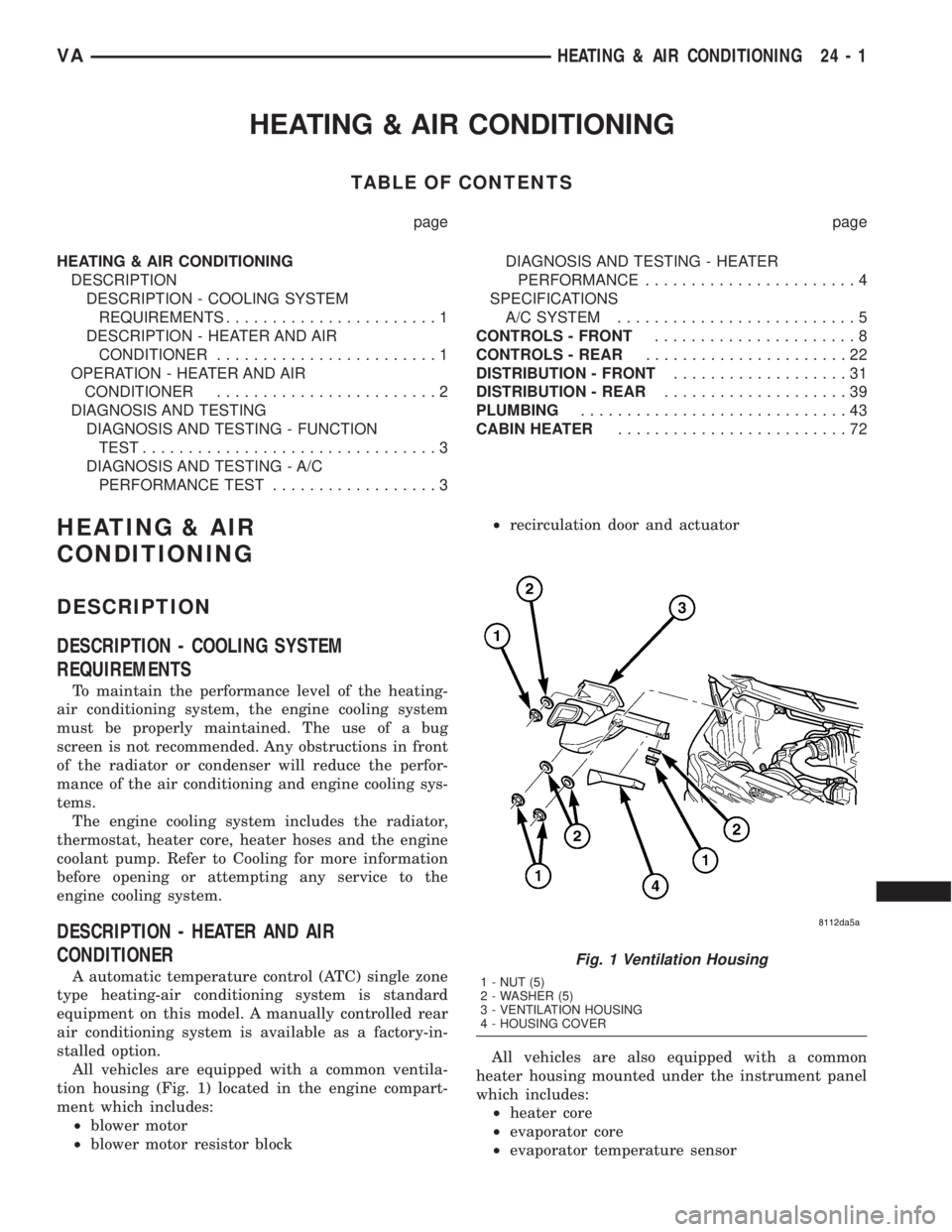
All vehicles are equipped with a common ventila-
tion housing (Fig. 1) located in the engine compart-
ment which includes:
²blower motor
²blower motor resistor block²recirculation door and actuator
All vehicles are also equipped with a common
heater housing mounted under the instrument panel
which includes:
²heater core
²evaporator core
²evaporator temperature sensor
Fig. 1 Ventilation Housing
1 - NUT (5)
2 - WASHER (5)
3 - VENTILATION HOUSING
4 - HOUSING COVER
VAHEATING & AIR CONDITIONING 24 - 1
Page 1131 of 1232
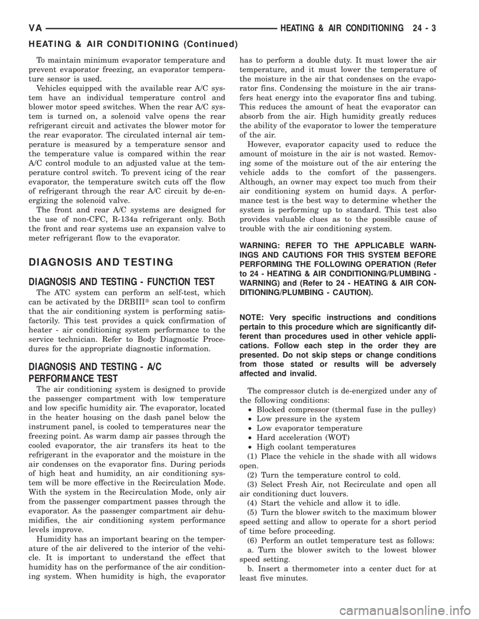
To maintain minimum evaporator temperature and
prevent evaporator freezing, an evaporator tempera-
ture sensor is used.
Vehicles equipped with the available rear A/C sys-
tem have an individual temperature control and
blower motor speed switches. When the rear A/C sys-
tem is turned on, a solenoid valve opens the rear
refrigerant circuit and activates the blower motor for
the rear evaporator. The circulated internal air tem-
perature is measured by a temperature sensor and
the temperature value is compared within the rear
A/C control module to an adjusted value at the tem-
perature control switch. To prevent icing of the rear
evaporator, the temperature switch cuts off the flow
of refrigerant through the rear A/C circuit by de-en-
ergizing the solenoid valve.
The front and rear A/C systems are designed for
the use of non-CFC, R-134a refrigerant only. Both
the front and rear systems use an expansion valve to
meter refrigerant flow to the evaporator.
DIAGNOSIS AND TESTING
DIAGNOSIS AND TESTING - FUNCTION TEST
The ATC system can perform an self-test, which
can be activated by the DRBIIItscan tool to confirm
that the air conditioning system is performing satis-
factorily. This test provides a quick confirmation of
heater - air conditioning system performance to the
service technician. Refer to Body Diagnostic Proce-
dures for the appropriate diagnostic information.
DIAGNOSIS AND TESTING - A/C
PERFORMANCE TEST
The air conditioning system is designed to provide
the passenger compartment with low temperature
and low specific humidity air. The evaporator, located
in the heater housing on the dash panel below the
instrument panel, is cooled to temperatures near the
freezing point. As warm damp air passes through the
cooled evaporator, the air transfers its heat to the
refrigerant in the evaporator and the moisture in the
air condenses on the evaporator fins. During periods
of high heat and humidity, an air conditioning sys-
tem will be more effective in the Recirculation Mode.
With the system in the Recirculation Mode, only air
from the passenger compartment passes through the
evaporator. As the passenger compartment air dehu-
midifies, the air conditioning system performance
levels improve.
Humidity has an important bearing on the temper-
ature of the air delivered to the interior of the vehi-
cle. It is important to understand the effect that
humidity has on the performance of the air condition-
ing system. When humidity is high, the evaporatorhas to perform a double duty. It must lower the air
temperature, and it must lower the temperature of
the moisture in the air that condenses on the evapo-
rator fins. Condensing the moisture in the air trans-
fers heat energy into the evaporator fins and tubing.
This reduces the amount of heat the evaporator can
absorb from the air. High humidity greatly reduces
the ability of the evaporator to lower the temperature
of the air.
However, evaporator capacity used to reduce the
amount of moisture in the air is not wasted. Remov-
ing some of the moisture out of the air entering the
vehicle adds to the comfort of the passengers.
Although, an owner may expect too much from their
air conditioning system on humid days. A perfor-
mance test is the best way to determine whether the
system is performing up to standard. This test also
provides valuable clues as to the possible cause of
trouble with the air conditioning system.
WARNING: REFER TO THE APPLICABLE WARN-
INGS AND CAUTIONS FOR THIS SYSTEM BEFORE
PERFORMING THE FOLLOWING OPERATION (Refer
to 24 - HEATING & AIR CONDITIONING/PLUMBING -
WARNING) and (Refer to 24 - HEATING & AIR CON-
DITIONING/PLUMBING - CAUTION).
NOTE: Very specific instructions and conditions
pertain to this procedure which are significantly dif-
ferent than procedures used in other vehicle appli-
cations. Follow each step in the order they are
presented. Do not skip steps or change conditions
from those stated or results will be adversely
affected and invalid.
The compressor clutch is de-energized under any of
the following conditions:
²Blocked compressor (thermal fuse in the pulley)
²Low pressure in the system
²Low evaporator temperature
²Hard acceleration (WOT)
²High coolant temperatures
(1) Place the vehicle in the shade with all widows
open.
(2) Turn the temperature control to cold.
(3) Select Fresh Air, not Recirculate and open all
air conditioning duct louvers.
(4) Start the vehicle and allow it to idle.
(5) Turn the blower switch to the maximum blower
speed setting and allow to operate for a short period
of time before proceeding.
(6) Perform an outlet temperature test as follows:
a. Turn the blower switch to the lowest blower
speed setting.
b. Insert a thermometer into a center duct for at
least five minutes.
VAHEATING & AIR CONDITIONING 24 - 3
HEATING & AIR CONDITIONING (Continued)
Page 1132 of 1232
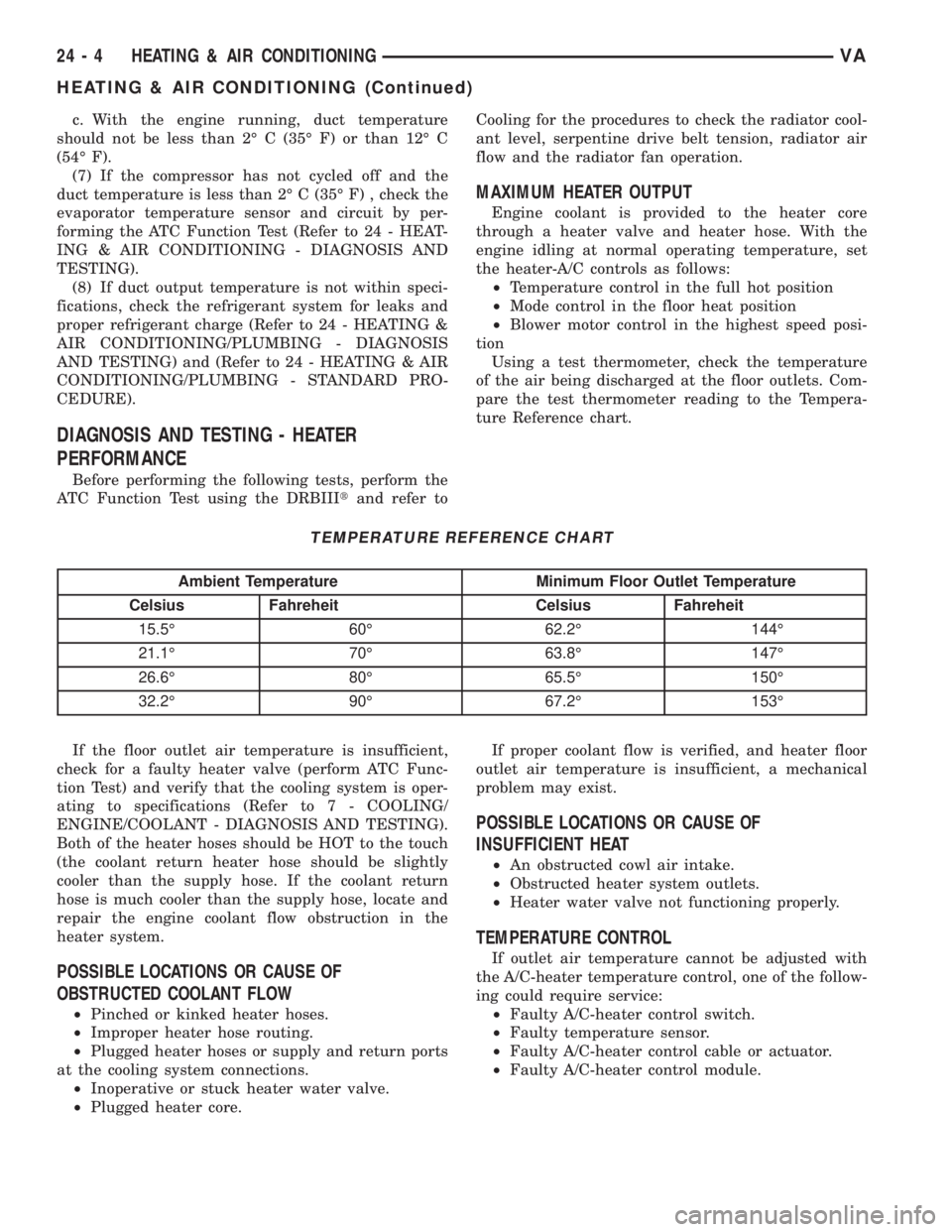
c. With the engine running, duct temperature
should not be less than 2É C (35É F) or than 12É C
(54É F).
(7) If the compressor has not cycled off and the
duct temperature is less than 2É C (35É F) , check the
evaporator temperature sensor and circuit by per-
forming the ATC Function Test (Refer to 24 - HEAT-
ING & AIR CONDITIONING - DIAGNOSIS AND
TESTING).
(8) If duct output temperature is not within speci-
fications, check the refrigerant system for leaks and
proper refrigerant charge (Refer to 24 - HEATING &
AIR CONDITIONING/PLUMBING - DIAGNOSIS
AND TESTING) and (Refer to 24 - HEATING & AIR
CONDITIONING/PLUMBING - STANDARD PRO-
CEDURE).
DIAGNOSIS AND TESTING - HEATER
PERFORMANCE
Before performing the following tests, perform the
ATC Function Test using the DRBIIItand refer toCooling for the procedures to check the radiator cool-
ant level, serpentine drive belt tension, radiator air
flow and the radiator fan operation.
MAXIMUM HEATER OUTPUT
Engine coolant is provided to the heater core
through a heater valve and heater hose. With the
engine idling at normal operating temperature, set
the heater-A/C controls as follows:
²Temperature control in the full hot position
²Mode control in the floor heat position
²Blower motor control in the highest speed posi-
tion
Using a test thermometer, check the temperature
of the air being discharged at the floor outlets. Com-
pare the test thermometer reading to the Tempera-
ture Reference chart.
TEMPERATURE REFERENCE CHART
Ambient Temperature Minimum Floor Outlet Temperature
Celsius Fahreheit Celsius Fahreheit
15.5É 60É 62.2É 144É
21.1É 70É 63.8É 147É
26.6É 80É 65.5É 150É
32.2É 90É 67.2É 153É
If the floor outlet air temperature is insufficient,
check for a faulty heater valve (perform ATC Func-
tion Test) and verify that the cooling system is oper-
ating to specifications (Refer to 7 - COOLING/
ENGINE/COOLANT - DIAGNOSIS AND TESTING).
Both of the heater hoses should be HOT to the touch
(the coolant return heater hose should be slightly
cooler than the supply hose. If the coolant return
hose is much cooler than the supply hose, locate and
repair the engine coolant flow obstruction in the
heater system.
POSSIBLE LOCATIONS OR CAUSE OF
OBSTRUCTED COOLANT FLOW
²Pinched or kinked heater hoses.
²Improper heater hose routing.
²Plugged heater hoses or supply and return ports
at the cooling system connections.
²Inoperative or stuck heater water valve.
²Plugged heater core.If proper coolant flow is verified, and heater floor
outlet air temperature is insufficient, a mechanical
problem may exist.
POSSIBLE LOCATIONS OR CAUSE OF
INSUFFICIENT HEAT
²An obstructed cowl air intake.
²Obstructed heater system outlets.
²Heater water valve not functioning properly.
TEMPERATURE CONTROL
If outlet air temperature cannot be adjusted with
the A/C-heater temperature control, one of the follow-
ing could require service:
²Faulty A/C-heater control switch.
²Faulty temperature sensor.
²Faulty A/C-heater control cable or actuator.
²Faulty A/C-heater control module.
24 - 4 HEATING & AIR CONDITIONINGVA
HEATING & AIR CONDITIONING (Continued)
Page 1171 of 1232
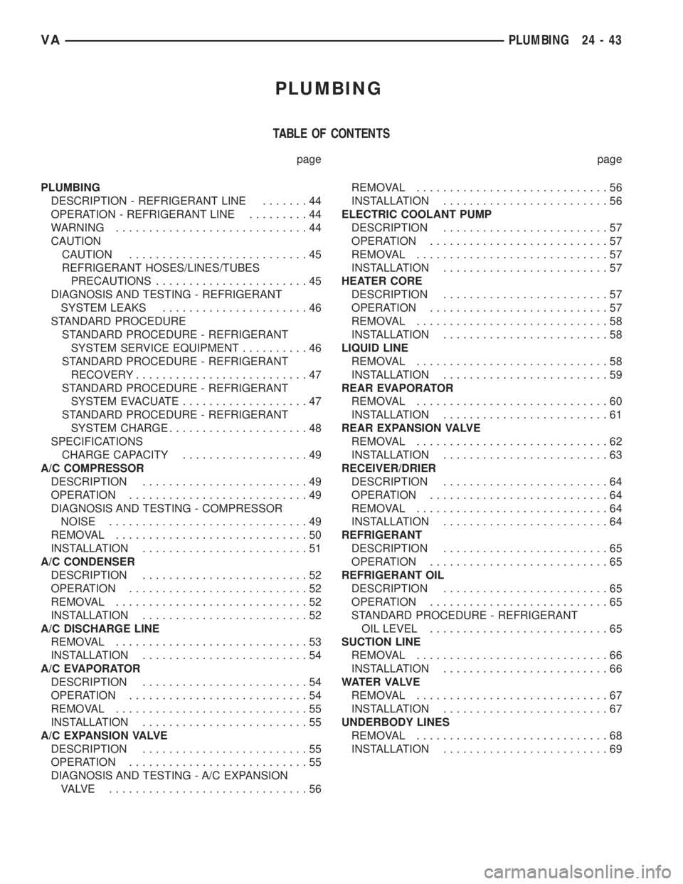
PLUMBING
TABLE OF CONTENTS
page page
PLUMBING
DESCRIPTION - REFRIGERANT LINE.......44
OPERATION - REFRIGERANT LINE.........44
WARNING.............................44
CAUTION
CAUTION...........................45
REFRIGERANT HOSES/LINES/TUBES
PRECAUTIONS.......................45
DIAGNOSIS AND TESTING - REFRIGERANT
SYSTEM LEAKS......................46
STANDARD PROCEDURE
STANDARD PROCEDURE - REFRIGERANT
SYSTEM SERVICE EQUIPMENT..........46
STANDARD PROCEDURE - REFRIGERANT
RECOVERY..........................47
STANDARD PROCEDURE - REFRIGERANT
SYSTEM EVACUATE...................47
STANDARD PROCEDURE - REFRIGERANT
SYSTEM CHARGE.....................48
SPECIFICATIONS
CHARGE CAPACITY...................49
A/C COMPRESSOR
DESCRIPTION.........................49
OPERATION...........................49
DIAGNOSIS AND TESTING - COMPRESSOR
NOISE..............................49
REMOVAL.............................50
INSTALLATION.........................51
A/C CONDENSER
DESCRIPTION.........................52
OPERATION...........................52
REMOVAL.............................52
INSTALLATION.........................52
A/C DISCHARGE LINE
REMOVAL.............................53
INSTALLATION.........................54
A/C EVAPORATOR
DESCRIPTION.........................54
OPERATION...........................54
REMOVAL.............................55
INSTALLATION.........................55
A/C EXPANSION VALVE
DESCRIPTION.........................55
OPERATION...........................55
DIAGNOSIS AND TESTING - A/C EXPANSION
VALVE ..............................56REMOVAL.............................56
INSTALLATION.........................56
ELECTRIC COOLANT PUMP
DESCRIPTION.........................57
OPERATION...........................57
REMOVAL.............................57
INSTALLATION.........................57
HEATER CORE
DESCRIPTION.........................57
OPERATION...........................57
REMOVAL.............................58
INSTALLATION.........................58
LIQUID LINE
REMOVAL.............................58
INSTALLATION.........................59
REAR EVAPORATOR
REMOVAL.............................60
INSTALLATION.........................61
REAR EXPANSION VALVE
REMOVAL.............................62
INSTALLATION.........................63
RECEIVER/DRIER
DESCRIPTION.........................64
OPERATION...........................64
REMOVAL.............................64
INSTALLATION.........................64
REFRIGERANT
DESCRIPTION.........................65
OPERATION...........................65
REFRIGERANT OIL
DESCRIPTION.........................65
OPERATION...........................65
STANDARD PROCEDURE - REFRIGERANT
OIL LEVEL...........................65
SUCTION LINE
REMOVAL.............................66
INSTALLATION.........................66
WAT E R VA LV E
REMOVAL.............................67
INSTALLATION.........................67
UNDERBODY LINES
REMOVAL.............................68
INSTALLATION.........................69
VAPLUMBING 24 - 43
Page 1214 of 1232
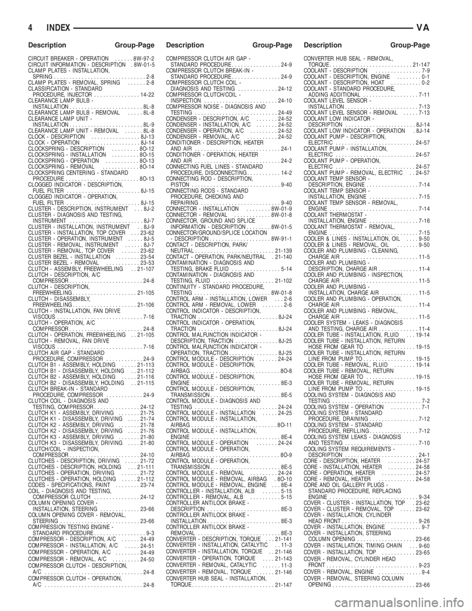
CIRCUIT BREAKER - OPERATION......8W-97-2
CIRCUIT INFORMATION - DESCRIPTION . 8W-01-5
CLAMP PLATES - INSTALLATION,
SPRING..............................2-8
CLAMP PLATES - REMOVAL, SPRING......2-8
CLASSIFICATION - STANDARD
PROCEDURE, INJECTOR...............14-22
CLEARANCE LAMP BULB -
INSTALLATION........................8L-8
CLEARANCE LAMP BULB - REMOVAL.....8L-8
CLEARANCE LAMP UNIT -
INSTALLATION........................8L-9
CLEARANCE LAMP UNIT - REMOVAL......8L-8
CLOCK - DESCRIPTION................8J-13
CLOCK - OPERATION..................8J-14
CLOCKSPRING - DESCRIPTION.........8O-12
CLOCKSPRING - INSTALLATION.........8O-15
CLOCKSPRING - OPERATION...........8O-13
CLOCKSPRING - REMOVAL............8O-14
CLOCKSPRING CENTERING - STANDARD
PROCEDURE........................8O-13
CLOGGED INDICATOR - DESCRIPTION,
FUEL FILTER........................8J-15
CLOGGED INDICATOR - OPERATION,
FUEL FILTER........................8J-15
CLUSTER - DESCRIPTION, INSTRUMENT . . . 8J-2
CLUSTER - DIAGNOSIS AND TESTING,
INSTRUMENT........................8J-7
CLUSTER - INSTALLATION, INSTRUMENT . . 8J-9
CLUSTER - INSTALLATION, TOP COVER . . . 23-62
CLUSTER - OPERATION, INSTRUMENT.....8J-5
CLUSTER - REMOVAL, INSTRUMENT......8J-7
CLUSTER - REMOVAL, TOP COVER......23-62
CLUSTER BEZEL - INSTALLATION........23-54
CLUSTER BEZEL - REMOVAL...........23-53
CLUTCH - ASSEMBLY, FREEWHEELING . . 21-107
CLUTCH - DESCRIPTION, A/C
COMPRESSOR........................24-8
CLUTCH - DESCRIPTION,
FREEWHEELING.....................21-105
CLUTCH - DISASSEMBLY,
FREEWHEELING.....................21-106
CLUTCH - INSTALLATION, FAN DRIVE
VISCOUS............................7-16
CLUTCH - OPERATION, A/C
COMPRESSOR........................24-8
CLUTCH - OPERATION, FREEWHEELING . . 21-105
CLUTCH - REMOVAL, FAN DRIVE
VISCOUS............................7-16
CLUTCH AIR GAP - STANDARD
PROCEDURE, COMPRESSOR............24-9
CLUTCH B1 - ASSEMBLY, HOLDING.....21-113
CLUTCH B1 - DISASSEMBLY, HOLDING . . 21-112
CLUTCH B2 - ASSEMBLY, HOLDING.....21-116
CLUTCH B2 - DISASSEMBLY, HOLDING . . 21-115
CLUTCH BREAK-IN - STANDARD
PROCEDURE, COMPRESSOR............24-9
CLUTCH COIL - DIAGNOSIS AND
TESTING, COMPRESSOR...............24-12
CLUTCH K1 - ASSEMBLY, DRIVING.......21-75
CLUTCH K1 - DISASSEMBLY, DRIVING....21-74
CLUTCH K2 - ASSEMBLY, DRIVING.......21-78
CLUTCH K2 - DISASSEMBLY, DRIVING....21-76
CLUTCH K3 - ASSEMBLY, DRIVING.......21-80
CLUTCH K3 - DISASSEMBLY, DRIVING....21-80
CLUTCH/COIL - INSPECTION,
COMPRESSOR.......................24-10
CLUTCHES - DESCRIPTION, DRIVING.....21-72
CLUTCHES - DESCRIPTION, HOLDING . . . 21-111
CLUTCHES - OPERATION, DRIVING......21-72
CLUTCHES - OPERATION, HOLDING.....21-112
CODES - SPECIFICATIONS, PAINT........23-74
COIL - DIAGNOSIS AND TESTING,
COMPRESSOR CLUTCH...............24-12
COLUMN OPENING COVER -
INSTALLATION, STEERING.............23-66
COLUMN OPENING COVER - REMOVAL,
STEERING..........................23-66
COMPRESSION TESTING ENGINE -
STANDARD PROCEDURE.................9-3
COMPRESSOR - DESCRIPTION, A/C......24-49
COMPRESSOR - INSTALLATION, A/C
.....24-51
COMPRESSOR - OPERATION, A/C
........24-49
COMPRESSOR - REMOVAL, A/C
.........24-50
COMPRESSOR CLUTCH - DESCRIPTION,
A/C
................................24-8
COMPRESSOR CLUTCH - OPERATION,
A/C
................................24-8COMPRESSOR CLUTCH AIR GAP -
STANDARD PROCEDURE................24-9
COMPRESSOR CLUTCH BREAK-IN -
STANDARD PROCEDURE................24-9
COMPRESSOR CLUTCH COIL -
DIAGNOSIS AND TESTING.............24-12
COMPRESSOR CLUTCH/COIL -
INSPECTION........................24-10
COMPRESSOR NOISE - DIAGNOSIS AND
TESTING...........................24-49
CONDENSER - DESCRIPTION, A/C.......24-52
CONDENSER - INSTALLATION, A/C.......24-52
CONDENSER - OPERATION, A/C.........24-52
CONDENSER - REMOVAL, A/C..........24-52
CONDITIONER - DESCRIPTION, HEATER
AND AIR ............................24-1
CONDITIONER - OPERATION, HEATER
AND AIR ............................24-2
CONNECTING FUEL LINES - STANDARD
PROCEDURE, DISCONNECTING...........14-2
CONNECTING ROD - DESCRIPTION,
PISTON.............................9-40
CONNECTING RODS - STANDARD
PROCEDURE, CHECKING AND
REPAIRING..........................9-40
CONNECTOR - INSTALLATION........8W-01-9
CONNECTOR - REMOVAL............8W-01-8
CONNECTOR, GROUND AND SPLICE
INFORMATION - DESCRIPTION........8W-01-5
CONNECTOR/GROUND/SPLICE LOCATION
- DESCRIPTION....................8W-91-1
CONTACT - DESCRIPTION, PARK/
NEUTRAL..........................21-139
CONTACT - OPERATION, PARK/NEUTRAL . 21-140
CONTAMINATION - DIAGNOSIS AND
TESTING, BRAKE FLUID................5-14
CONTAMINATION - DIAGNOSIS AND
TESTING, FLUID....................21-102
CONTINUITY - STANDARD PROCEDURE,
TESTING.........................8W-01-8
CONTROL ARM - INSTALLATION, LOWER . . . 2-6
CONTROL ARM - REMOVAL, LOWER.......2-6
CONTROL INDICATOR - DESCRIPTION,
TRACTION..........................8J-24
CONTROL INDICATOR - OPERATION,
TRACTION..........................8J-24
CONTROL MALFUNCTION INDICATOR -
DESCRIPTION, TRACTION..............8J-25
CONTROL MALFUNCTION INDICATOR -
OPERATION, TRACTION................8J-25
CONTROL MODULE - DESCRIPTION......24-24
CONTROL MODULE - DESCRIPTION,
AIRBAG.............................8O-8
CONTROL MODULE - DESCRIPTION,
ENGINE.............................8E-3
CONTROL MODULE - DESCRIPTION,
TRANSMISSION.......................8E-5
CONTROL MODULE - DIAGNOSIS AND
TESTING...........................24-24
CONTROL MODULE - INSTALLATION.....24-25
CONTROL MODULE - INSTALLATION,
AIRBAG............................8O-11
CONTROL MODULE - INSTALLATION,
ENGINE.............................8E-4
CONTROL MODULE - OPERATION.......24-24
CONTROL MODULE - OPERATION,
AIRBAG.............................8O-9
CONTROL MODULE - OPERATION,
TRANSMISSION.......................8E-5
CONTROL MODULE - REMOVAL.........24-24
CONTROL MODULE - REMOVAL, AIRBAG . 8O-10
CONTROL MODULE - REMOVAL, ENGINE . . . 8E-4
CONTROLLER - INSTALLATION, ALB......5-15
CONTROLLER - REMOVAL, ALB..........5-15
CONTROLLER ANTILOCK BRAKE -
DESCRIPTION........................8E-3
CONTROLLER ANTILOCK BRAKE -
INSTALLATION........................8E-3
CONTROLLER ANTILOCK BRAKE -
REMOVAL...........................8E-3
CONVERTER - DESCRIPTION, TORQUE . . . 21-141
CONVERTER - INSTALLATION, CATALYTIC . . 11-3
CONVERTER - INSTALLATION, TORQUE
. . 21-146
CONVERTER - OPERATION, TORQUE
....21-143
CONVERTER - REMOVAL, CATALYTIC
......11-3
CONVERTER - REMOVAL, TORQUE
......21-146
CONVERTER HUB SEAL - INSTALLATION,
TORQUE
...........................21-147CONVERTER HUB SEAL - REMOVAL,
TORQUE...........................21-147
COOLANT - DESCRIPTION...............7-9
COOLANT - DESCRIPTION, ENGINE........0-1
COOLANT - DESCRIPTION, HOAT..........0-2
COOLANT - STANDARD PROCEDURE,
ADDING ADDITIONAL..................7-11
COOLANT LEVEL SENSOR -
INSTALLATION........................7-13
COOLANT LEVEL SENSOR - REMOVAL.....7-13
COOLANT LOW INDICATOR -
DESCRIPTION.......................8J-14
COOLANT LOW INDICATOR - OPERATION . 8J-14
COOLANT PUMP - DESCRIPTION,
ELECTRIC..........................24-57
COOLANT PUMP - INSTALLATION,
ELECTRIC..........................24-57
COOLANT PUMP - OPERATION,
ELECTRIC..........................24-57
COOLANT PUMP - REMOVAL, ELECTRIC . . 24-57
COOLANT TEMP SENSOR -
DESCRIPTION, ENGINE.................7-14
COOLANT TEMP SENSOR -
INSTALLATION, ENGINE................7-15
COOLANT TEMP SENSOR - REMOVAL,
ENGINE.............................7-14
COOLANT THERMOSTAT -
INSTALLATION, ENGINE................7-16
COOLANT THERMOSTAT - REMOVAL,
ENGINE.............................7-15
COOLER & LINES - INSTALLATION, OIL....9-50
COOLER & LINES - REMOVAL, OIL.......9-50
COOLER AND PLUMBING - CLEANING,
CHARGE AIR.........................11-5
COOLER AND PLUMBING -
DESCRIPTION, CHARGE AIR.............11-4
COOLER AND PLUMBING - INSPECTION,
CHARGE AIR.........................11-5
COOLER AND PLUMBING -
INSTALLATION, CHARGE AIR............11-5
COOLER AND PLUMBING - OPERATION,
CHARGE AIR.........................11-4
COOLER AND PLUMBING - REMOVAL,
CHARGE AIR.........................11-5
COOLER SYSTEM - LEAKS - DIAGNOSIS
AND TESTING, CHARGE AIR.............11-4
COOLER TUBE - INSTALLATION, FLUID . . . 19-14
COOLER TUBE - INSTALLATION, RETURN
HOSE FROM GEAR TO................19-15
COOLER TUBE - INSTALLATION, RETURN
LINE FROM PUMP TO.................19-15
COOLER TUBE - REMOVAL, FLUID.......19-14
COOLER TUBE - REMOVAL, RETURN
HOSE FROM GEAR TO................19-15
COOLER TUBE - REMOVAL, RETURN
LINE FROM PUMP TO.................19-15
COOLING SYSTEM - DIAGNOSIS AND
TESTING.............................7-2
COOLING SYSTEM - OPERATION..........7-1
COOLING SYSTEM - STANDARD
PROCEDURE, DRAINING................7-12
COOLING SYSTEM - STANDARD
PROCEDURE, REFILLING................7-12
COOLING SYSTEM LEAKS - DIAGNOSIS
AND TESTING........................7-10
COOLING SYSTEM REQUIREMENTS -
DESCRIPTION........................24-1
CORE - DESCRIPTION, HEATER.........24-57
CORE - INSTALLATION, HEATER.........24-58
CORE - OPERATION, HEATER...........24-57
CORE - REMOVAL, HEATER............24-58
CORE AND OIL GALLERY PLUGS -
STANDARD PROCEDURE, REPLACING
ENGINE.............................9-34
COVER - CLUSTER - INSTALLATION, TOP . 23-62
COVER - CLUSTER - REMOVAL, TOP.....23-62
COVER - INSTALLATION, CYLINDER
HEAD FRONT.........................9-26
COVER - INSTALLATION, ENGINE..........9-7
COVER - INSTALLATION, STEERING
COLUMN OPENING...................23-66
COVER - INSTALLATION, TIMING CHAIN
. . . 9-60
COVER - INSTALLATION, TOP
...........23-65
COVER - REMOVAL, CYLINDER HEAD
FRONT
..............................9-23
COVER - REMOVAL, ENGINE
..............9-4
COVER - REMOVAL, STEERING COLUMN
OPENING
...........................23-66
4 INDEXVA
Description Group-Page Description Group-Page Description Group-Page