2005 MERCEDES-BENZ SPRINTER warning light
[x] Cancel search: warning lightPage 1040 of 1232
VISUAL INSPECTION BEFORE WATER LEAK TESTS
Verify that floor and body plugs are in place, body
drains are clear, and body components are properly
aligned and sealed. If component alignment or seal-
ing is necessary, refer to the appropriate section of
this group for proper procedures.
WATER LEAK TESTS
WARNING: DO NOT USE ELECTRIC SHOP LIGHTS
OR TOOLS IN WATER TEST AREA. PERSONAL
INJURY CAN RESULT.
When the conditions causing a water leak have
been determined, simulate the conditions as closely
as possible.
²If a leak occurs with the vehicle parked in a
steady light rain, flood the leak area with an open-
ended garden hose.
²If a leak occurs while driving at highway speeds
in a steady rain, test the leak area with a reasonable
velocity stream or fan spray of water. Direct the
spray in a direction comparable to actual conditions.
²If a leak occurs when the vehicle is parked on an
incline, hoist the end or side of the vehicle to simu-
late this condition. This method can be used when
the leak occurs when the vehicle accelerates, stops or
turns. If the leak occurs on acceleration, hoist the
front of the vehicle. If the leak occurs when braking,
hoist the back of the vehicle. If the leak occurs on left
turns, hoist the left side of the vehicle. If the leak
occurs on right turns, hoist the right side of the vehi-
cle. For hoisting recommendations (Refer to LUBRI-
CATION & MAINTENANCE/HOISTING -
STANDARD PROCEDURE).
WATER LEAK DETECTION
To detect a water leak point-of-entry, do a water
test and watch for water tracks or droplets forming
on the inside of the vehicle. If necessary, remove inte-
rior trim covers or panels to gain visual access to the
leak area. If the hose cannot be positioned without
being held, have someone help do the water test.
Some water leaks must be tested for a considerable
length of time to become apparent. When a leak
appears, find the highest point of the water track or
drop. The highest point usually will show the point of
entry. After leak point has been found, repair the
leak and water test to verify that the leak has
stopped.
Locating the entry point of water that is leaking
into a cavity between panels can be difficult. The
trapped water may splash or run from the cavity,
often at a distance from the entry point. Most water
leaks of this type become apparent after accelerating,
stopping, turning, or when on an incline.MIRROR INSPECTION METHOD
When a leak point area is visually obstructed, use
a suitable mirror to gain visual access. A mirror can
also be used to deflect light to a limited-access area
to assist in locating a leak point.
BRIGHT LIGHT LEAK TEST METHOD
Some water leaks in the luggage compartment can
be detected without water testing. Position the vehi-
cle in a brightly lit area. From inside the darkened
luggage compartment inspect around seals and body
seams. If necessary, have a helper direct a drop light
over the suspected leak areas around the luggage
compartment. If light is visible through a normally
sealed location, water could enter through the open-
ing.
PRESSURIZED LEAK TEST METHOD
When a water leak into the passenger compart-
ment cannot be detected by water testing, pressurize
the passenger compartment and soap test exterior of
the vehicle. To pressurize the passenger compart-
ment, close all doors and windows, start engine, and
set heater control to high blower in HEAT position. If
engine can not be started, connect a charger to the
battery to ensure adequate voltage to the blower.
With interior pressurized, apply dish detergent solu-
tion to suspected leak area on the exterior of the
vehicle. Apply detergent solution with spray device or
soft bristle brush. If soap bubbles occur at a body
seam, joint, seal or gasket, the leak entry point could
be at that location.
DIAGNOSIS AND TESTING - WIND NOISE
Wind noise is the result of most air leaks. Air leaks
can be caused by poor sealing, improper body compo-
nent alignment, body seam porosity, or missing plugs
in the engine compartment or door hinge pillar areas.
All body sealing points should be airtight in normal
driving conditions. Moving sealing surfaces will not
always seal airtight under all conditions. At times,
side glass or door seals will allow wind noise to be
noticed in the passenger compartment during high
cross winds. Over compensating on door or glass
adjustments to stop wind noise that occurs under
severe conditions can cause premature seal wear and
excessive closing or latching effort. After a repair pro-
cedure has been performed, test vehicle to verify
noise has stopped before returning vehicle to use.
VISUAL INSPECTION BEFORE TESTS
Verify that floor and body plugs are in place and
body components are aligned and sealed. If compo-
nent alignment or sealing is necessary, refer to the
appropriate section of this group for proper proce-
dures.
23 - 2 BODYVA
BODY (Continued)
Page 1112 of 1232
PAINT
TABLE OF CONTENTS
page page
PAINT
SPECIFICATIONS - PAINT CODES..........74
BASECOAT/CLEARCOAT FINISH
DESCRIPTION.........................74
PAINT TOUCH-UP
DESCRIPTION.........................74STANDARD PROCEDURE - PAINT TOUCH-UP . 75
FINESSE SANDING/BUFFING & POLISH
DESCRIPTION.........................75
PAINT
SPECIFICATIONS - PAINT CODES
EXTERIOR COLORS
EXTERIOR COLOR DAIMLERCHRYSLER
CODE
Steel Blue MB 5389
Brilliant Blue MB 5362
Orchid Green MB 6464
Flame Red MB 3534
Arctic White MB 9147
Black Blue MB 7103
Calcite Yellow MB 1234
Piedmont Red MB 3636
Hycanith Blue MB 5376
Black Gray MB 7103
Stone Gray MB 7160
Silver Gray MB 7708
BASECOAT/CLEARCOAT
FINISH
DESCRIPTION
The original equipment finish is a multi step pro-
cess that involves cleaning, applying electro de-posi-tion (E-coat), anti-chip primer, basecoat, and
clearcoat steps.
On most vehicles a two-part paint application
(basecoat/clearcoat) is used. Color paint that is
applied to primer is called basecoat. The clear coat
protects the basecoat from ultraviolet light and pro-
vides a durable high-gloss finish.
CAUTION: Do not use abrasive chemicals or com-
pounds on painted surfaces. Damage to finish can
result.
Do not use harsh alkaline based cleaning solvents
on painted surfaces. Damage to finish or color can
result.
PAINT TOUCH-UP
DESCRIPTION
When a painted metal surface has been scratched
or chipped, it should be touched-up as soon as possi-
ble to avoid corrosion. For best results, use MOPARt
Scratch Filler/Primer, Touch-Up Paints and Clear Top
Coat.
WARNING: USE AN OSHA APPROVED RESPIRATOR
AND SAFETY GLASSES WHEN SPRAYING PAINT
OR SOLVENTS IN A CONFINED AREA. PERSONAL
INJURY CAN RESULT.
23 - 74 PAINTVA
Page 1113 of 1232
STANDARD PROCEDURE - PAINT TOUCH-UP
(1) Scrape loose paint and corrosion from inside
scratch or chip.
(2) Clean affected area with MOPARtTar/Road
Oil Remover or equivalent, and allow to dry.
(3) Fill the inside of the scratch or chip with a coat
of filler/primer. Do not overlap primer onto good sur-
face finish. The applicator brush should be wet
enough to puddle-fill the scratch or chip without run-
ning. Do not stroke brush applicator on body surface.
Allow the filler/primer to dry hard.
(4) Cover the filler/primer with color touch-up
paint. Do not overlap touch-up color onto the original
color coat around the scratch or chip. Butt the new
color to the original color, if possible. Do not stroke
applicator brush on body surface. Allow touch-up
paint to dry hard.
(5) On vehicles without clearcoat, the touch-up
color can be lightly finesse sanded (1500 grit) and
polished with rubbing compound.
(6) On vehicles with clearcoat, apply clear top coat
to touch-up paint with the same technique as
described in Step 4. Allow clear top coat to dry hard.
If desired, Step 5 can be performed on clear top coat.
WARNING: AVOID PROLONGED SKIN CONTACT
WITH PETROLEUM OR ALCOHOL ± BASED CLEAN-ING SOLVENTS. PERSONAL INJURY CAN
RESULT.AVOID PROLONGED SKIN CONTACT WITH
PETROLEUM OR ALCOHOL ± BASED CLEANING
SOLVENTS. PERSONAL INJURY CAN RESULT.
FINESSE SANDING/BUFFING &
POLISH
DESCRIPTION
CAUTION: Do not remove more than .5 mils of
clearcoat finish, if equipped. Basecoat paint must
retain clearcoat for durability.
Use a Paint Thickness Gauge #PR-ETG-2X or equiv-
alent to determine film thickness before and after
the repair.
Minor acid etching, orange peel, or smudging in
clearcoat or single-stage finishes can be reduced with
light finesse sanding, hand buffing, and polishing.If
the finish has been finesse sanded in the past,
it cannot be repeated. Finesse sanding opera-
tion should be performed by a trained automo-
tive paint technician.
VAPAINT 23 - 75
PAINT TOUCH-UP (Continued)
Page 1151 of 1232
DIAGNOSIS AND TESTING
Before testing the rear blower motor switch, verify
that the front A/C system is functional by performing
the ATC Fuction Test using the DRBIIItscan tool.
Use a volt/ohmmeter to test the rear blower motor
switch. For circuit descriptions and diagrams, refer
to the appropriate wiring information. The wiring
information includes wiring diagrams, proper wire
and connector repair procedures, details of wire har-
ness routing and retention, connector pin-out infor-
mation and location views for the various wire
harness connectors, splices and grounds.
WARNING: ON VEHICLES EQUIPPED WITH AIR-
BAGS, DISABLE THE AIRBAG SYSTEM BEFORE
ATTEMPTING ANY STEERING WHEEL, STEERING
COLUMN, OR INSTRUMENT PANEL COMPONENT
DIAGNOSIS OR SERVICE. DISCONNECT AND ISO-
LATE THE BATTERY NEGATIVE (GROUND) CABLE,
THEN WAIT TWO MINUTES FOR THE AIRBAG SYS-
TEM CAPACITOR TO DISCHARGE BEFORE PER-
FORMING FURTHER DIAGNOSIS OR SERVICE. THIS
IS THE ONLY SURE WAY TO DISABLE THE AIRBAG
SYSTEM. FAILURE TO TAKE THE PROPER PRE-
CAUTIONS COULD RESULT IN ACCIDENTAL AIR-
BAG DEPLOYMENT AND POSSIBLE PERSONAL
INJURY.
(1) Disconnect and isolate the battery negative
cable.
(2) Unplug the wire harness connector from the
rear blower motor switch.
(3) Check for continuity between terminal 10 and
terminals 1, 7 and 4 of the blower motor switch. In
all instances, there should be continuity.
NOTE: To check the switch's internal circuits, con-
nect the negative lead of the ohmmeter to terminal
10 and the positive ohmmeter lead to terminals 1, 7
and 4. To check the switch's integral light emitting
diodes, reverse the ohmmeter leads.
(4) Check for continuity between the rear blower
motor switch terminals 3 and 7 as you move the
blower motor switch to each of the two speed posi-
tions, and the Off position. There should be continu-
ity in only one blower motor switch speed position.
(5) Check for continuity between the rear blower
motor switch terminals 4 and 8 as you move the
blower motor switch to each of the two speed posi-
tions, and the Off position. There should be continu-
ity in only the other blower motor switch speed
position.
(6) If OK, test and repair the rear blower motor
switch wire harness circuits. If not OK, replace the
faulty rear blower motor switch.
REMOVAL
NOTE: The rear blower motor switch is used only
on models with the optional rear A/C unit.
(1) Disconnect and isolate the battery negative
cable.
(2) Remove the blower motor switch from the
switch panel.
(3) Disconnect the wire harness connector from the
rear blower motor switch and remove the switch from
the vehicle.
INSTALLATION
(1) Connect the wire harness connector to the rear
blower motor switch.
(2) Install the blower motor switch into the switch
panel.
(3) Reconnect the battery negative cable.
BLOWER MOTOR RELAY
DESCRIPTION
The blower motor relays are an International Stan-
dards Organization (ISO)-type relay. The relays are
electro-mechanical devices which when energized,
directs fused battery current to the rear blower
motor. The relay coils are energized when they
receives a voltage signal from the blower motor
switch.
OPERATION
When the rear blower motor switch is in the low
speed position, the switch directs a voltage signal to
the high side of rear blower relay #1 and energizes
its relay coil. When energized, the low side of blower
relay #1 directs fused battery current through an
integral blower resistor to the rear blower motor.
When in the high speed position, the rear blower
switch directs a voltage signal to the high side of
rear blower relay #2 and energizes its relay coil.
When energized, the low side of blower relay #2
directs fused battery current through an integral
blower resistor to the rear blower motor.
The rear blower motor relays are located in the
relay block of the rear evaporator housing. Refer to
the appropriate wiring diagrams for more informa-
tion.
The blower motor relay cannot be repaired and, if
faulty or damaged, it must be replaced.
VACONTROLS - REAR 24 - 23
BLOWER MOTOR SWITCH (Continued)
Page 1172 of 1232
PLUMBING
DESCRIPTION - REFRIGERANT LINE
The refrigerant lines and hoses are used to carry
the refrigerant between the various air conditioning
system components. A barrier hose design with a
nylon tube, which is sandwiched between rubber lay-
ers, is used for the R-134a air conditioning system on
this vehicle. This nylon tube helps to further contain
the R-134a refrigerant, which has a smaller molecu-
lar structure than R-12 refrigerant. The ends of the
refrigerant hoses are made from lightweight alumi-
num or steel, and commonly use braze-less fittings.
Any kinks or sharp bends in the refrigerant plumb-
ing will reduce the capacity of the entire air condi-
tioning system. Kinks and sharp bends reduce the
flow of refrigerant in the system. A good rule for the
flexible hose refrigerant lines is to keep the radius of
all bends at least ten times the diameter of the hose.
In addition, the flexible hose refrigerant lines should
be routed so they are at least 80 millimeters (3
inches) from the exhaust manifold.
OPERATION - REFRIGERANT LINE
High pressures are produced in the refrigerant sys-
tem when the air conditioning compressor is operat-
ing. Extreme care must be exercised to make sure
that each of the refrigerant system connections is
pressure-tight and leak free. It is a good practice to
inspect all flexible hose refrigerant lines at least once
a year to make sure they are in good condition and
properly routed.
The refrigerant lines and hoses cannot be repaired
and, if faulty or damaged, they must be replaced.
WARNING
WARNING: THE AIR CONDITIONING SYSTEM CON-
TAINS REFRIGERANT UNDER HIGH PRESSURE.
SEVERE PERSONAL INJURY MAY RESULT FROM
IMPROPER SERVICE PROCEDURES. REPAIRS
SHOULD ONLY BE PERFORMED BY QUALIFIED
SERVICE PERSONNEL.AVOID BREATHING THE REFRIGERANT AND
REFRIGERANT OIL VAPOR OR MIST. EXPOSURE
MAY IRRITATE THE EYES, NOSE, AND/OR THROAT.
WEAR EYE PROTECTION WHEN SERVICING THE
AIR CONDITIONING REFRIGERANT SYSTEM. SERI-
OUS EYE INJURY CAN RESULT FROM DIRECT
CONTACT WITH THE REFRIGERANT. IF EYE CON-
TACT OCCURS, SEEK MEDICAL ATTENTION IMME-
DIATELY.
DO NOT EXPOSE THE REFRIGERANT TO OPEN
FLAME. POISONOUS GAS IS CREATED WHEN
REFRIGERANT IS BURNED. AN ELECTRONIC LEAK
DETECTOR IS RECOMMENDED.
IF ACCIDENTAL SYSTEM DISCHARGE OCCURS,
VENTILATE THE WORK AREA BEFORE RESUMING
SERVICE. LARGE AMOUNTS OF REFRIGERANT
RELEASED IN A CLOSED WORK AREA WILL DIS-
PLACE THE OXYGEN AND CAUSE SUFFOCATION.
THE EVAPORATION RATE OF R-134a REFRIGER-
ANT AT AVERAGE TEMPERATURE AND ALTITUDE
IS EXTREMELY HIGH. AS A RESULT, ANYTHING
THAT COMES IN CONTACT WITH THE REFRIGER-
ANT WILL FREEZE. ALWAYS PROTECT THE SKIN
OR DELICATE OBJECTS FROM DIRECT CONTACT
WITH THE REFRIGERANT.
THE R-134a SERVICE EQUIPMENT OR THE VEHI-
CLE REFRIGERANT SYSTEM SHOULD NOT BE
PRESSURE TESTED OR LEAK TESTED WITH COM-
PRESSED AIR. SOME MIXTURES OF AIR AND
R-134a HAVE BEEN SHOWN TO BE COMBUSTIBLE
AT ELEVATED PRESSURES. THESE MIXTURES ARE
POTENTIALLY DANGEROUS, AND MAY RESULT IN
FIRE OR EXPLOSION CAUSING INJURY OR PROP-
ERTY DAMAGE.
24 - 44 PLUMBINGVA
Page 1190 of 1232
(11) Remove the tape or plug from the liquid line
fittings and the solenoid valve outlet port and the
expansion valve inlet port.
(12) Lubricate new rubber o-ring seals with clean
refrigerant oil and install them on the liquid line fit-
tings.
(13) Install the liquid line between the rear expan-
sion valve and the solenoid valve.
(14) Install and tighten the nuts that secures the
liquid line fittings to the rear expansion valve and
solenoid valve. Tighten the nuts to 16 N´m (142 in.
lbs.).
(15) Install the rear A/C housing (Refer to 24 -
HEATING & AIR CONDITIONING/DISTRIBUTION/
REAR A/C HEATER HOUSING - INSTALLATION).
NOTE: If the evaporator is being replaced, add 30
milliliters (1 fluid ounce) of refrigerant oil to the
refrigerant system.
REAR EXPANSION VALVE
REMOVAL
WARNING: REFER TO THE APPLICABLE WARN-
INGS AND CAUTIONS FOR THIS SYSTEM BEFORE
PERFORMING THE FOLLOWING OPERATION (Refer
to 24 - HEATING & AIR CONDITIONING/PLUMBING -
WARNING) and (Refer to 24 - HEATING & AIR CON-
DITIONING/PLUMBING - CAUTION).
(1) Recover the refrigerant from the A/C system
(Refer to 24 - HEATING & AIR CONDITIONING/
PLUMBING - STANDARD PROCEDURE).
(2) Disconnect and isolate the battery negative
cable.
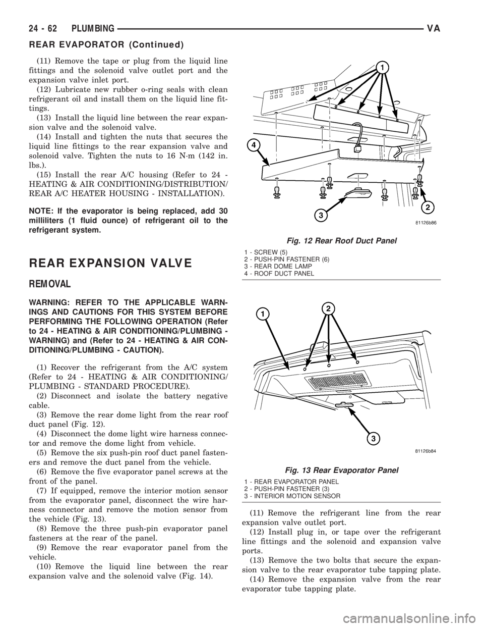
(3) Remove the rear dome light from the rear roof
duct panel (Fig. 12).
(4) Disconnect the dome light wire harness connec-
tor and remove the dome light from vehicle.
(5) Remove the six push-pin roof duct panel fasten-
ers and remove the duct panel from the vehicle.
(6) Remove the five evaporator panel screws at the
front of the panel.
(7) If equipped, remove the interior motion sensor
from the evaporator panel, disconnect the wire har-
ness connector and remove the motion sensor from
the vehicle (Fig. 13).
(8) Remove the three push-pin evaporator panel
fasteners at the rear of the panel.
(9) Remove the rear evaporator panel from the
vehicle.
(10) Remove the liquid line between the rear
expansion valve and the solenoid valve (Fig. 14).(11) Remove the refrigerant line from the rear
expansion valve outlet port.
(12) Install plug in, or tape over the refrigerant
line fittings and the solenoid and expansion valve
ports.
(13) Remove the two bolts that secure the expan-
sion valve to the rear evaporator tube tapping plate.
(14) Remove the expansion valve from the rear
evaporator tube tapping plate.
Fig. 12 Rear Roof Duct Panel
1 - SCREW (5)
2 - PUSH-PIN FASTENER (6)
3 - REAR DOME LAMP
4 - ROOF DUCT PANEL
Fig. 13 Rear Evaporator Panel
1 - REAR EVAPORATOR PANEL
2 - PUSH-PIN FASTENER (3)
3 - INTERIOR MOTION SENSOR
24 - 62 PLUMBINGVA
REAR EVAPORATOR (Continued)
Page 1213 of 1232
BRAKE/PARK BRAKE INDICATOR -
OPERATION.........................8J-12
BRAKE/PARK LAMP BULB -
INSTALLATION........................8L-7
BRAKE/PARK LAMP BULB - REMOVAL.....8L-7
BRAKES, SPECIAL TOOLS................5-7
BREAKER - DESCRIPTION, CIRCUIT....8W-97-2
BREAKER - DIAGNOSIS AND TESTING,
CIRCUIT.........................8W-97-2
BREAKER - OPERATION, CIRCUIT.....8W-97-2
BREAK-IN - STANDARD PROCEDURE,
COMPRESSOR CLUTCH................24-9
BUCKLE - INSTALLATION, FRONT SEAT
BELT ..............................8O-23
BUCKLE - REMOVAL, FRONT SEAT BELT . . 8O-22
BULB - INSTALLATION, BACKUP LAMP....8L-6
BULB - INSTALLATION, BRAKE/PARK
LAMP...............................8L-7
BULB - INSTALLATION, CARGO/DOME
LAMP..............................8L-27
BULB - INSTALLATION, CENTER HIGH
MOUNTED STOP LAMP.................8L-7
BULB - INSTALLATION, CLEARANCE
LAMP...............................8L-8
BULB - INSTALLATION, DOME
LAMP/INTRUSION SENSOR.............8L-30
BULB - INSTALLATION, DOME/READING
LAMP..............................8L-29
BULB - INSTALLATION, ENTRY/EXIT
LAMP..............................8L-32
BULB - INSTALLATION, FOG LAMP.......8L-10
BULB - INSTALLATION, FRONT POSITION
LAMP..............................8L-14
BULB - INSTALLATION, FRONT
TURN/PARK/SIDE MARKER LAMP.......8L-15
BULB - INSTALLATION, HIGH BEAM
HEADLAMP.........................8L-17
BULB - INSTALLATION, LICENSE PLATE
LAMP..............................8L-18
BULB - INSTALLATION, LOW BEAM
HEADLAMP.........................8L-19
BULB - INSTALLATION, REAR SIDE
MARKER LAMP......................8L-21
BULB - INSTALLATION, REAR TURN
LAMP..............................8L-22
BULB - INSTALLATION, REPEATER LAMP . . 8L-22
BULB - REMOVAL, BACKUP LAMP........8L-5
BULB - REMOVAL, BRAKE/PARK LAMP....8L-7
BULB - REMOVAL, CARGO/DOME LAMP . . 8L-27
BULB - REMOVAL, CENTER HIGH
MOUNTED STOP LAMP.................8L-7
BULB - REMOVAL, CLEARANCE LAMP.....8L-8
BULB - REMOVAL, DOME LAMP/
INTRUSION SENSOR..................8L-30
BULB - REMOVAL, DOME/READING
LAMP..............................8L-29
BULB - REMOVAL, ENTRY/EXIT LAMP....8L-31
BULB - REMOVAL, FOG LAMP..........8L-10
BULB - REMOVAL, FRONT POSITION
LAMP..............................8L-14
BULB - REMOVAL, FRONT TURN/PARK/
SIDE MARKER LAMP.................8L-14
BULB - REMOVAL, HIGH BEAM
HEADLAMP.........................8L-17
BULB - REMOVAL, LICENSE PLATE
LAMP..............................8L-17
BULB - REMOVAL, LOW BEAM
HEADLAMP.........................8L-18
BULB - REMOVAL, REAR SIDE MARKER
LAMP..............................8L-21
BULB - REMOVAL, REAR TURN LAMP....8L-21
BULB - REMOVAL, REPEATER LAMP.....8L-22
BULKHEAD - INSTALLATION............8L-29
BULKHEAD - REMOVAL................8L-28
BULKHEAD TRIM PANEL -
INSTALLATION.......................23-69
BULKHEAD TRIM PANEL -
INSTALLATION, BACKLITE..............23-81
BULKHEAD TRIM PANEL - REMOVAL.....23-69
BULKHEAD TRIM PANEL - REMOVAL,
BACKLITE..........................23-81
BUMPER - STEP - INSTALLATION, REAR
. . . 13-3
BUMPER - STEP - REMOVAL, REAR
.......13-3
BUMPER - STEPS - INSTALLATION,
FRONT
..............................13-2
BUMPER - STEPS - REMOVAL, FRONT
.....13-2
BURNT FLUID - DIAGNOSIS AND
TESTING, CAUSES OF
................21-102BUSHINGS - INSTALLATION..............2-3
BUSHINGS - REMOVAL..................2-3
BUZZ, SQUEAK & RATTLE - STANDARD
PROCEDURE........................23-10
CABIN HEATER - DESCRIPTION.........24-72
CABIN HEATER - OPERATION...........24-72
CABLE - DESCRIPTION.................8P-3
CABLE - DIAGNOSIS AND TESTING,
GEARSHIFT........................21-109
CABLE - INSTALLATION, ANTENNA BODY . . 8A-1
CABLE - INSTALLATION, GEARSHIFT....21-109
CABLE - INSTALLATION, INSTRUMENT
PANEL ANTENNA......................8A-2
CABLE - INSTALLATION, LATCH RELEASE . 23-51
CABLE - INSTALLATION, PARK LOCK....21-126
CABLE - REMOVAL, ANTENNA BODY......8A-1
CABLE - REMOVAL, GEARSHIFT........21-109
CABLE - REMOVAL, INSTRUMENT PANEL
ANTENNA...........................8A-1
CABLE - REMOVAL, LATCH RELEASE.....23-51
CABLE - REMOVAL, PARK LOCK........21-125
CABLE TENSIONER - INSTALLATION......5-23
CABLE TENSIONER - REMOVAL..........5-23
CABLES - ADJUSTMENT, PARKING
BRAKE..............................5-25
CABLES - DESCRIPTION, BATTERY.......8F-14
CABLES - DIAGNOSIS AND TESTING,
BATTERY...........................8F-14
CABLES - INSTALLATION, BATTERY......8F-16
CABLES - INSTALLATION, MODE DOOR . . . 24-19
CABLES - OPERATION, BATTERY........8F-14
CABLES - REMOVAL, BATTERY..........8F-16
CABLES - REMOVAL, MODE DOOR.......24-19
CAMSHAFT POSITION - STANDARD
PROCEDURE, CHECKING................9-27
CAMSHAFT POSITION SENSOR -
DESCRIPTION.......................14-19
CAMSHAFT POSITION SENSOR -
INSTALLATION.......................14-19
CAMSHAFT POSITION SENSOR -
OPERATION.........................14-19
CAMSHAFT POSITION SENSOR -
REMOVAL..........................14-19
CAMSHAFT(S) - INSTALLATION..........9-29
CAMSHAFT(S) - REMOVAL..............9-28
CAP - DESCRIPTION, RADIATOR
PRESSURE..........................7-18
CAP - DIAGNOSIS AND TESTING,
RADIATOR PRESSURE.................7-19
CAP - OPERATION, RADIATOR
PRESSURE..........................7-18
CAPACITIES - SPECIFICATIONS, FLUID......0-4
CAPACITY, SPECIFICATIONS - CHARGE . . . 24-49
CARGO/DOME LAMP BULB -
INSTALLATION.......................8L-27
CARGO/DOME LAMP BULB - REMOVAL . . . 8L-27
CARGO/DOME LAMP UNIT -
INSTALLATION.......................8L-28
CARGO/DOME LAMP UNIT - REMOVAL . . . 8L-28
CARPETS AND FLOOR MATS -
INSTALLATION.......................23-70
CARPETS AND FLOOR MATS - REMOVAL . 23-69
CARRIER - INSTALLATION, SPARE TIRE . . . 22-10
CARRIER - REMOVAL, SPARE TIRE......22-10
CATALYTIC CONVERTER - INSTALLATION . . . 11-3
CATALYTIC CONVERTER - REMOVAL......11-3
CAUSES OF BURNT FLUID - DIAGNOSIS
AND TESTING
......................21-102
CAUTION - CAUTION
..................24-45
CAUTION - REFRIGERANT HOSES/LINES/
TUBES PRECAUTIONS
.................24-45
CAUTION, CAUTION
...................24-45
CAUTION, INTERIOR
..................23-67
CENTER - DESCRIPTION, POWER
DISTRIBUTION
....................8W-97-3
CENTER - OPERATION, POWER
DISTRIBUTION
....................8W-97-3
CENTER BEARING - INSTALLATION
........3-9
CENTER BEARING - REMOVAL
............3-8
CENTER BEZEL - INSTALLATION,
INSTRUMENT PANEL
..................23-55
CENTER BEZEL - REMOVAL,
INSTRUMENT PANEL
..................23-55
CENTER HIGH MOUNTED STOP LAMP
BULB - INSTALLATION
.................8L-7
CENTER HIGH MOUNTED STOP LAMP
BULB - REMOVAL
.....................8L-7CENTER HIGH MOUNTED STOP LAMP
UN - INSTALLATION...................8L-8
CENTER HIGH MOUNTED STOP LAMP
UN - REMOVAL.......................8L-8
CENTER ROLLER ARM - INSTALLATION . . . 23-38
CENTER ROLLER ARM - REMOVAL......23-37
CENTER TRACK - INSTALLATION........23-39
CENTER TRACK - REMOVAL............23-38
CENTERING - STANDARD PROCEDURE,
CLOCKSPRING......................8O-13
CENTRAL TIMER MODULE -
DESCRIPTION........................8E-1
CENTRAL TIMER MODULE - DIAGNOSIS
AND TESTING........................8E-2
CENTRAL TIMER MODULE -
INSTALLATION........................8E-2
CENTRAL TIMER MODULE - OPERATION . . . 8E-2
CENTRAL TIMER MODULE - REMOVAL....8E-2
CHAIN - INSTALLATION, OIL PUMP.......9-54
CHAIN - INSTALLATION, TIMING.........9-67
CHAIN - REMOVAL, OIL PUMP...........9-53
CHAIN - REMOVAL, TIMING.............9-63
CHAIN COVER - INSTALLATION, TIMING . . . 9-60
CHAIN COVER - REMOVAL, TIMING.......9-59
CHAIN TENSIONER - INSTALLATION,
TIMING.............................9-71
CHAIN TENSIONER - REMOVAL, TIMING . . . 9-70
CHAIN TENSIONING RAIL -
INSTALLATION, TIMING.................9-66
CHAIN TENSIONING RAIL - REMOVAL,
TIMING.............................9-63
CHARGE - STANDARD PROCEDURE,
REFRIGERANT SYSTEM...............24-48
CHARGE AIR COOLER AND PLUMBING -
CLEANING...........................11-5
CHARGE AIR COOLER AND PLUMBING -
DESCRIPTION........................11-4
CHARGE AIR COOLER AND PLUMBING -
INSPECTION.........................11-5
CHARGE AIR COOLER AND PLUMBING -
INSTALLATION........................11-5
CHARGE AIR COOLER AND PLUMBING -
OPERATION..........................11-4
CHARGE AIR COOLER AND PLUMBING -
REMOVAL...........................11-5
CHARGE AIR COOLER SYSTEM - LEAKS
- DIAGNOSIS AND TESTING.............11-4
CHARGE CAPACITY, SPECIFICATIONS.....24-49
CHARGING - STANDARD PROCEDURE,
BATTERY............................8F-8
CHARGING INDICATOR - DESCRIPTION . . . 8J-13
CHARGING INDICATOR - OPERATION.....8J-13
CHART - SPECIFICATIONS, TORQUE....5-29,5-5
CHART - SPECIFICATIONS, TORQUE.....19-10,
19-14,19-5,19-9
CHART - SPECIFICATIONS, TORQUE....2-12,2-2
CHART, SPECIFICATIONS - TORQUE.......5-22
CHART, SPECIFICATIONS - TORQUE.......22-5
CHECK - INSTALLATION..........23-13,23-24
CHECK - REMOVAL..............23-13,23-24
CHECK OIL LEVEL - STANDARD
PROCEDURE.......................21-102
CHECK VALVE - DESCRIPTION...........8R-7
CHECK VALVE - INSTALLATION..........8R-7
CHECK VALVE - OPERATION.............8R-7
CHECK VALVE - REMOVAL..............8R-7
CHECKING AND REPAIRING
CONNECTING RODS - STANDARD
PROCEDURE.........................9-40
CHECKING BATTERY ELECTROLYTE
LEVEL - STANDARD PROCEDURE........8F-12
CHECKING CAMSHAFT POSITION -
STANDARD PROCEDURE................9-27
CHECKS - DIAGNOSIS AND TESTING,
PRELIMINARY.........................7-1
CHIME WARNING SYSTEM - DIAGNOSIS
AND TESTING........................8B-2
CHIME/BUZZER - DESCRIPTION..........8B-1
CHIME/BUZZER - OPERATION............8B-1
CIGAR LIGHTER OUTLET -
DESCRIPTION.....................8W-97-1
CIGAR LIGHTER OUTLET - DIAGNOSIS
AND TESTING
.....................8W-97-2
CIGAR LIGHTER OUTLET - OPERATION
. 8W-97-2
CIGAR LIGHTER OUTLET - REMOVAL
. . 8W-97-2
CIRCUIT BREAKER - DESCRIPTION
....8W-97-2
CIRCUIT BREAKER - DIAGNOSIS AND
TESTING
.........................8W-97-2
VAINDEX 3
Description Group-Page Description Group-Page Description Group-Page
Page 1228 of 1232
TUBE - INSTALLATION, FLUID COOLER . . . 19-14
TUBE - INSTALLATION, RETURN HOSE
FROM GEAR TO COOLER..............19-15
TUBE - INSTALLATION, RETURN LINE
FROM PUMP TO COOLER..............19-15
TUBE - REMOVAL, EXHAUST...........24-73
TUBE - REMOVAL, FLUID COOLER.......19-14
TUBE - REMOVAL, RETURN HOSE FROM
GEAR TO COOLER....................19-15
TUBE - REMOVAL, RETURN LINE FROM
PUMP TO COOLER...................19-15
TURBOCHARGER - DESCRIPTION.........11-6
TURBOCHARGER - OPERATION..........11-6
TURBOCHARGER SYSTEM -
DESCRIPTION........................11-3
TURBOCHARGER SYSTEM - OPERATION . . . 11-4
TURN LAMP BULB - INSTALLATION,
REAR..............................8L-22
TURN LAMP BULB - REMOVAL, REAR....8L-21
TURN SIGNAL INDICATOR -
DESCRIPTION.......................8J-25
TURN SIGNAL INDICATOR - OPERATION . . 8J-25
TURN SIGNAL RELAY - INSTALLATION....8L-24
TURN SIGNAL RELAY - REMOVAL.......8L-24
TURNING LOOP ADJUSTER -
INSTALLATION, SEAT BELT.............8O-34
TURNING LOOP ADJUSTER - REMOVAL,
SEAT BELT .........................8O-33
TURN/PARK/SIDE MARKER LAMP BULB
- INSTALLATION, FRONT...............8L-15
TURN/PARK/SIDE MARKER LAMP BULB
- REMOVAL, FRONT..................8L-14
UN - INSTALLATION, CENTER HIGH
MOUNTED STOP LAMP.................8L-8
UN - REMOVAL, CENTER HIGH
MOUNTED STOP LAMP.................8L-8
UNDER HOOD BATTERY INSTALLATION,
INSTALLATION.......................8F-13
UNDER HOOD BATTERY REMOVAL,
REMOVAL..........................8F-12
UNDERBODY LINES - INSTALLATION.....24-69
UNDERBODY LINES - REMOVAL.........24-68
UNIT - ADJUSTMENT, FRONT LAMP......8L-12
UNIT - ASSEMBLY, ELECTROHYDRAULIC . . 21-95
UNIT - DESCRIPTION,
ELECTROHYDRAULIC.................21-82
UNIT - DISASSEMBLY,
ELECTROHYDRAULIC.................21-92
UNIT - INSTALLATION, ASH RECEIVER/
CIGAR LIGHTER LAMP................8L-27
UNIT - INSTALLATION, CARGO/DOME
LAMP..............................8L-28
UNIT - INSTALLATION, CLEARANCE
LAMP...............................8L-9
UNIT - INSTALLATION, DOME/READING
LAMP..............................8L-30
UNIT - INSTALLATION,
ELECTROHYDRAULIC................21-100
UNIT - INSTALLATION, ENTRY/EXIT
LAMP..............................8L-32
UNIT - INSTALLATION, FRONT LAMP.....8L-12
UNIT - INSTALLATION, LICENSE PLATE
LAMP..............................8L-18
UNIT - INSTALLATION, REPEATER LAMP . . 8L-23
UNIT - INSTALLATION, TAIL LAMP.......8L-23
UNIT - OPERATION,
ELECTROHYDRAULIC.................21-87
UNIT - REMOVAL, ASH RECEIVER/CIGAR
LIGHTER LAMP......................8L-27
UNIT - REMOVAL, CARGO/DOME LAMP . . . 8L-28
UNIT - REMOVAL, CLEARANCE LAMP.....8L-8
UNIT - REMOVAL, DOME/READING
LAMP..............................8L-30
UNIT - REMOVAL, ELECTROHYDRAULIC . . 21-92
UNIT - REMOVAL, ENTRY/EXIT LAMP....8L-32
UNIT - REMOVAL, FRONT LAMP.........8L-12
UNIT - REMOVAL, LICENSE PLATE LAMP . . 8L-18
UNIT - REMOVAL, REPEATER LAMP......8L-22
UNIT - REMOVAL, TAIL LAMP...........8L-23
UNIT / SENSOR - DESCRIPTION, FUEL
LEVEL SENDING.....................14-15
UNIT / SENSOR - INSTALLATION, FUEL
LEVEL SENDING
.....................14-15
UNIT / SENSOR - REMOVAL, FUEL
LEVEL SENDING
.....................14-15
UPPER ROLLER ARM - INSTALLATION
....23-37
UPPER ROLLER ARM - REMOVAL
.......23-37
USAGE - DESCRIPTION, FASTENER
.....Intro.-5USE WIRING DIAGRAMS -
DESCRIPTION, HOW TO.............8W-01-1
USING MICRO 420 BATTERY TESTER -
STANDARD PROCEDURE...............8F-11
VACUUM PUMP - DESCRIPTION..........9-48
VACUUM PUMP - INSTALLATION.........9-49
VACUUM PUMP - OPERATION...........9-48
VACUUM PUMP - REMOVAL.............9-48
VACUUM TRANSDUCER - INSTALLATION . . . 11-8
VACUUM TRANSDUCER - REMOVAL......11-7
VALVE - DESCRIPTION.................25-1
VALVE - DESCRIPTION, A/C EXPANSION . . 24-55
VALVE - DESCRIPTION, CHECK..........8R-7
VALVE - DESCRIPTION, SOLENOID.......24-27
VALVE - DIAGNOSIS AND TESTING, A/C
EXPANSION.........................24-56
VALVE - DIAGNOSIS AND TESTING,
SOLENOID..........................24-27
VALVE - INSTALLATION.................25-2
VALVE - INSTALLATION, A/C EXPANSION . . 24-56
VALVE - INSTALLATION, CHECK..........8R-7
VALVE - INSTALLATION, REAR
EXPANSION.........................24-63
VALVE - INSTALLATION, SOLENOID......24-28
VALVE - INSTALLATION, WATER.........24-67
VALVE - OPERATION...................25-1
VALVE - OPERATION, A/C EXPANSION....24-55
VALVE - OPERATION, CHECK..............8R-7
VALVE - OPERATION, SOLENOID........24-27
VALVE - REMOVAL....................25-2
VALVE - REMOVAL, A/C EXPANSION.....24-56
VALVE - REMOVAL, CHECK..............8R-7
VALVE - REMOVAL, REAR EXPANSION....24-62
VALVE - REMOVAL, SOLENOID..........24-27
VALVE - REMOVAL, WATER.............24-67
VALVE SPRINGS - INSTALLATION.........9-32
VALVE SPRINGS - REMOVAL............9-31
VALVES - INSTALLATION................9-33
VALVES - REMOVAL...................9-31
VEHICLE IDENTIFICATION NUMBER -
DESCRIPTION......................Intro.-1
VEHICLE THEFT SECURITY -
DESCRIPTION........................8Q-1
VEHICLE THEFT SECURITY - DIAGNOSIS
AND TESTING........................8Q-1
VEHICLE THEFT SECURITY - OPERATION . . 8Q-1
VERIFICATION TEST - STANDARD
PROCEDURE.........................8O-7
VIBRATION - DIAGNOSIS AND TESTING,
TIRE NOISE OR.......................22-8
VIBRATION DAMPER - INSTALLATION.....9-48
VIBRATION DAMPER - REMOVAL.........9-47
VIEW MIRROR - GLASS -
INSTALLATION, SIDE..................23-49
VIEW MIRROR - GLASS - REMOVAL,
SIDE..............................23-49
VIEW MIRROR - INSTALLATION, SIDE....23-48
VIEW MIRROR - REMOVAL, REAR.......23-72
VIEW MIRROR - REMOVAL, SIDE........23-48
VIEW MIRROR SUPPORT BRACKET -
INSTALLATION, REAR.................23-72
VISCOUS CLUTCH - INSTALLATION, FAN
DRIVE..............................7-16
VISCOUS CLUTCH - REMOVAL, FAN
DRIVE..............................7-16
VISOR - INSTALLATION, SUN...........23-73
VISOR - REMOVAL, SUN...............23-73
VOLTAGE DROP - STANDARD
PROCEDURE, TESTING FOR A........8W-01-8
VOLTAGE POTENTIAL - STANDARD
PROCEDURE, TESTING OF...........8W-01-7
VOLTAGE REGULATOR - DESCRIPTION....8F-23
VOLTAGE TEST - STANDARD
PROCEDURE, OPEN-CIRCUIT...........8F-10
WAIT-TO-START INDICATOR -
DESCRIPTION.......................8J-26
WAIT-TO-START INDICATOR -
OPERATION.........................8J-26
WARNING - INSTALLATION.............23-83
WARNING - REMOVAL................23-82
WARNING - SAFETY PRECAUTIONS AND
WARNINGS
..........................23-1
WARNING - WARNING
.................14-1
WARNING - WINDSHIELD SAFETY
PRECAUTIONS
.......................23-82
WARNING, HIGH FUEL SYSTEM
PRESSURE
..........................14-1
WARNING, PLUMBING
................24-44WARNING SYSTEM - DIAGNOSIS AND
TESTING, CHIME......................8B-2
WARNING, WARNING..................14-1
WARNINGS, GENERAL..............8W-01-6
WARNINGS, RESTRAINT SYSTEM........8O-5
WARNINGS, WARNING - SAFETY
PRECAUTIONS........................23-1
WASHER FLUID INDICATOR -
DESCRIPTION.......................8J-27
WASHER FLUID INDICATOR -
OPERATION.........................8J-27
WASHER FLUID LEVEL SWITCH -
DESCRIPTION........................8R-7
WASHER FLUID LEVEL SWITCH -
OPERATION..........................8R-8
WASHER HOSES/TUBES - DESCRIPTION . . . 8R-8
WASHER HOSES/TUBES - OPERATION.....8R-9
WASHER NOZZLE - DESCRIPTION........8R-9
WASHER NOZZLE - INSTALLATION.......8R-9
WASHER NOZZLE - OPERATION..........8R-9
WASHER NOZZLE - REMOVAL...........8R-9
WASHER PUMP/MOTOR - DESCRIPTION . . . 8R-9
WASHER PUMP/MOTOR - INSTALLATION . 8R-10
WASHER PUMP/MOTOR - OPERATION . . . 8R-10
WASHER PUMP/MOTOR - REMOVAL.....8R-10
WASHER RESERVOIR - DESCRIPTION....8R-11
WASHER RESERVOIR - INSTALLATION . . . 8R-12
WASHER RESERVOIR - OPERATION......8R-11
WASHER RESERVOIR - REMOVAL.......8R-11
WASHER SYSTEM - CLEANING, WIPER....8R-5
WASHER SYSTEM - DIAGNOSIS AND
TESTING, WIPER.....................8R-5
WASHER SYSTEM - INSPECTION, WIPER . . 8R-6
WATER FROM FUEL FILTER - STANDARD
PROCEDURES, DRAINING...............14-2
WATER IN FUEL SENSOR -
DESCRIPTION.......................14-16
WATER IN FUEL SENSOR - OPERATION . . . 14-16
WATER LEAKS - DIAGNOSIS AND
TESTING............................23-1
WATER PUMP - INSTALLATION..........7-20
WATER PUMP - REMOVAL..............7-19
WATER VALVE - INSTALLATION.........24-67
WATER VALVE - REMOVAL.............24-67
WATER-IN-FUEL INDICATOR -
DESCRIPTION.......................8J-27
WATER-IN-FUEL INDICATOR -
OPERATION.........................8J-28
WEAR INDICATOR - DESCRIPTION,
BRAKE.............................8J-12
WEAR INDICATOR - OPERATION, BRAKE . . 8J-12
WEAR INDICATORS - DIAGNOSIS AND
TESTING, TREAD......................22-8
WEAR PATTERNS - DIAGNOSIS AND
TESTING, TIRE.......................22-8
WEATHERSTRIP - INSTALLATION, FRONT
DOOR INNER BELT...................23-87
WEATHERSTRIP - INSTALLATION, FRONT
DOOR OUTER BELT...................23-87
WEATHERSTRIP - REMOVAL, FRONT
DOOR INNER BELT...................23-87
WEATHERSTRIP - REMOVAL, FRONT
DOOR OUTER BELT...................23-87
WHEEL - INSTALLATION, STEERING.......19-7
WHEEL - INSTALLATION, TONE..........5-31
WHEEL - REMOVAL, STEERING..........19-7
WHEEL - REMOVAL, TONE..............5-31
WHEEL ALIGNMENT - DESCRIPTION......2-17
WHEEL ALIGNMENT - SPECIFICATIONS....2-19
WHEEL BALANCE - STANDARD
PROCEDURE, TIRE....................22-3
WHEEL INSPECTION, DIAGNOSIS AND
TESTING...........................22-11
WHEEL INSTALLATION - STANDARD
PROCEDURE, DUAL REAR.............22-12
WHEEL REPLACEMENT - STANDARD
PROCEDURE........................22-11
WHEEL RUNOUT - DIAGNOSIS AND
TESTING, TIRE.......................22-1
WHEEL SPEED SENSOR -
INSTALLATION, FRONT
.................5-30
WHEEL SPEED SENSOR -
INSTALLATION, REAR
..................5-31
WHEEL SPEED SENSOR - REMOVAL,
FRONT
..............................5-30
WHEEL SPEED SENSOR - REMOVAL,
REAR
...............................5-30
WHEELS - DESCRIPTION
..............22-11
18 INDEXVA
Description Group-Page Description Group-Page Description Group-Page