2005 MERCEDES-BENZ SPRINTER coolant level
[x] Cancel search: coolant levelPage 749 of 1232
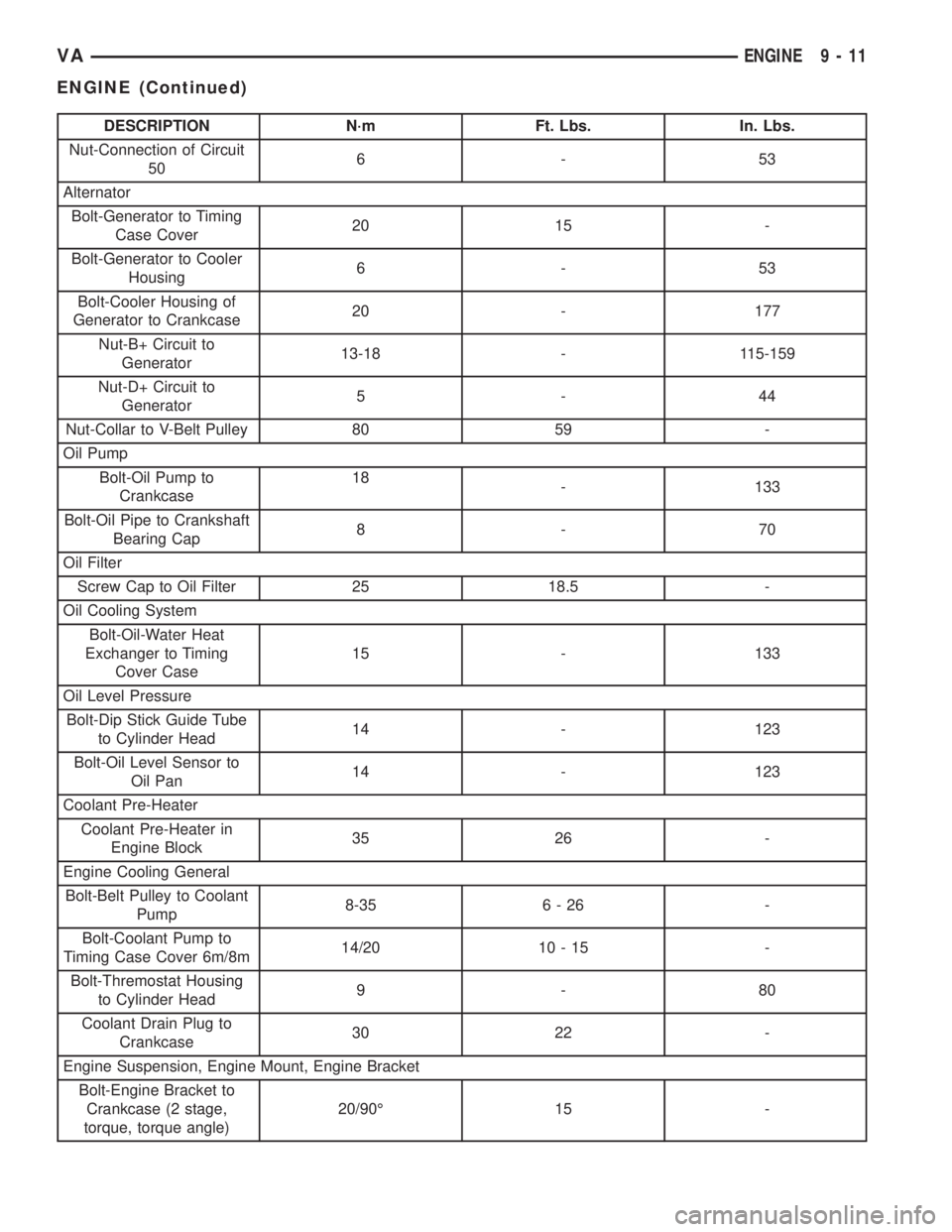
DESCRIPTION N´m Ft. Lbs. In. Lbs.
Nut-Connection of Circuit
506-53
Alternator
Bolt-Generator to Timing
Case Cover20 15 -
Bolt-Generator to Cooler
Housing6-53
Bolt-Cooler Housing of
Generator to Crankcase20 - 177
Nut-B+ Circuit to
Generator13-18 - 115-159
Nut-D+ Circuit to
Generator5-44
Nut-Collar to V-Belt Pulley 80 59 -
Oil Pump
Bolt-Oil Pump to
Crankcase18
- 133
Bolt-Oil Pipe to Crankshaft
Bearing Cap8-70
Oil Filter
Screw Cap to Oil Filter 25 18.5 -
Oil Cooling System
Bolt-Oil-Water Heat
Exchanger to Timing
Cover Case15 - 133
Oil Level Pressure
Bolt-Dip Stick Guide Tube
to Cylinder Head14 - 123
Bolt-Oil Level Sensor to
Oil Pan14 - 123
Coolant Pre-Heater
Coolant Pre-Heater in
Engine Block35 26 -
Engine Cooling General
Bolt-Belt Pulley to Coolant
Pump8-35 6 - 26 -
Bolt-Coolant Pump to
Timing Case Cover 6m/8m14/20 10 - 15 -
Bolt-Thremostat Housing
to Cylinder Head9-80
Coolant Drain Plug to
Crankcase30 22 -
Engine Suspension, Engine Mount, Engine Bracket
Bolt-Engine Bracket to
Crankcase (2 stage,
torque, torque angle)20/90É 15 -
VAENGINE 9 - 11
ENGINE (Continued)
Page 764 of 1232
BELT/CHAIN AND SPROCKETS - INSTALLATION)
Tighten to 80N´m (59 lbs.ft.).
(20) Remove retaining lock for crankshaft/starter
ring gear.
(21) Install air intake tube at turbocharger (Refer
to 11 - EXHAUST SYSTEM/TURBOCHARGER SYS-
TEM - INSTALLATION).
(22) Install engine cover (Refer to 9 - ENGINE -
INSTALLATION).
NOTE: DO NOT pressure test cooling system until
engine has reached operating temperature.
(23) Refill cooling system with proper coolant mix-
ture to proper level (Refer to 7 - COOLING/ENGINE/
COOLANT - STANDARD PROCEDURE).
(24) Connect negative battery cable.
WARNING: USE EXTREME CAUTION WHEN THE
ENGINE IS OPERATING. DO NOT STAND IN A
DIRECT LINE WITH THE FAN. DO NOT PUT YOUR
HANDS NEAR THE PULLEYS, BELTS OR FAN. DO
NOT WEAR LOOSE CLOTHES.
(25) Start engine and inspect for leaks. Care must
be taken to observe the fuel system warning (Refer to
14 - FUEL SYSTEM - WARNING)
INSTALLATION - CYLINDER HEAD FRONT
COVER
NOTE: Thoroughly clean all mating surfaces with
appropriate solvents to assure that no grease or oil
is present during reassembly.
NOTE: Dowel pins are used as a guide during
assembly and must remain in the proper position to
assure a good sealing surface.
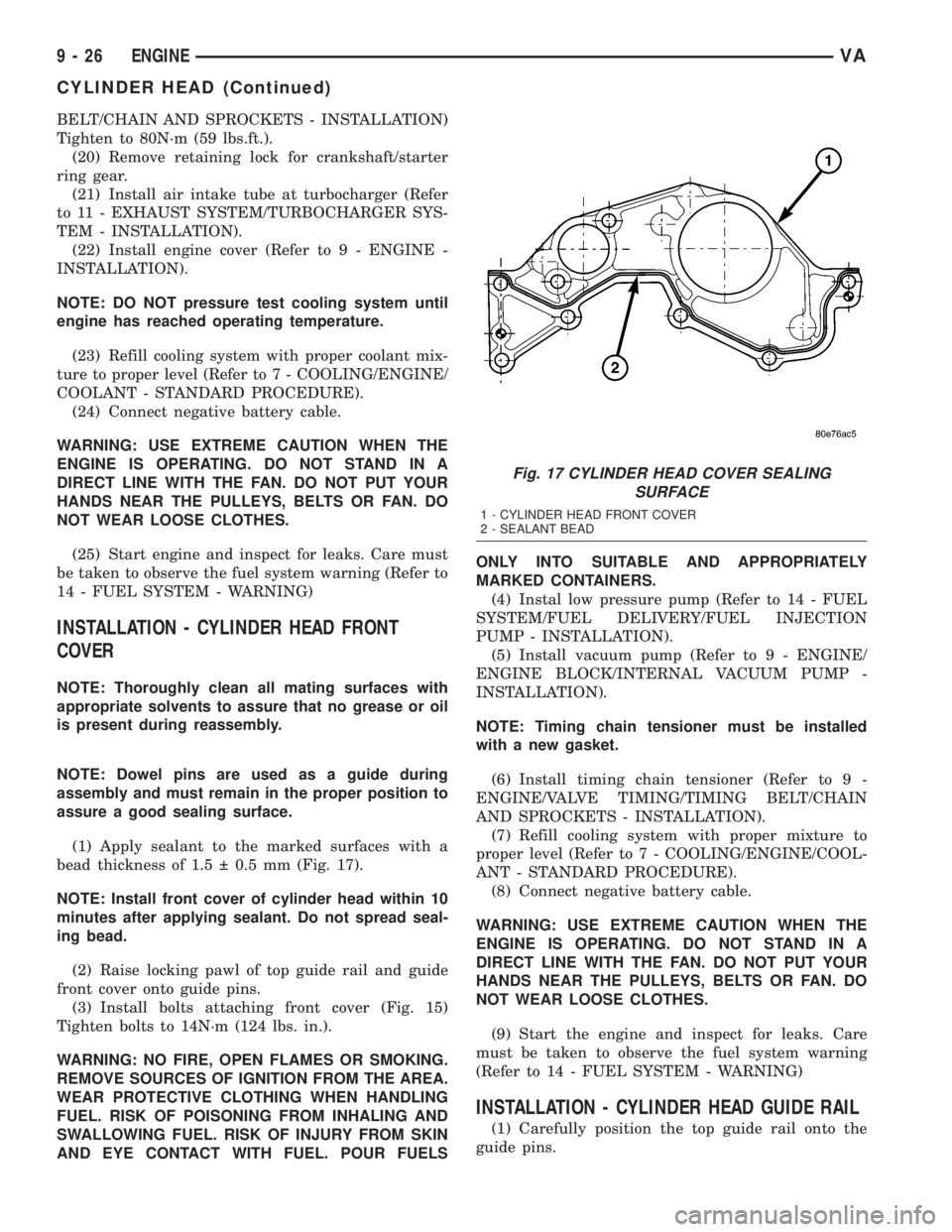
(1) Apply sealant to the marked surfaces with a
bead thickness of 1.5 0.5 mm (Fig. 17).
NOTE: Install front cover of cylinder head within 10
minutes after applying sealant. Do not spread seal-
ing bead.
(2) Raise locking pawl of top guide rail and guide
front cover onto guide pins.
(3) Install bolts attaching front cover (Fig. 15)
Tighten bolts to 14N´m (124 lbs. in.).
WARNING: NO FIRE, OPEN FLAMES OR SMOKING.
REMOVE SOURCES OF IGNITION FROM THE AREA.
WEAR PROTECTIVE CLOTHING WHEN HANDLING
FUEL. RISK OF POISONING FROM INHALING AND
SWALLOWING FUEL. RISK OF INJURY FROM SKIN
AND EYE CONTACT WITH FUEL. POUR FUELSONLY INTO SUITABLE AND APPROPRIATELY
MARKED CONTAINERS.
(4) Instal low pressure pump (Refer to 14 - FUEL
SYSTEM/FUEL DELIVERY/FUEL INJECTION
PUMP - INSTALLATION).
(5) Install vacuum pump (Refer to 9 - ENGINE/
ENGINE BLOCK/INTERNAL VACUUM PUMP -
INSTALLATION).
NOTE: Timing chain tensioner must be installed
with a new gasket.
(6) Install timing chain tensioner (Refer to 9 -
ENGINE/VALVE TIMING/TIMING BELT/CHAIN
AND SPROCKETS - INSTALLATION).
(7) Refill cooling system with proper mixture to
proper level (Refer to 7 - COOLING/ENGINE/COOL-
ANT - STANDARD PROCEDURE).
(8) Connect negative battery cable.
WARNING: USE EXTREME CAUTION WHEN THE
ENGINE IS OPERATING. DO NOT STAND IN A
DIRECT LINE WITH THE FAN. DO NOT PUT YOUR
HANDS NEAR THE PULLEYS, BELTS OR FAN. DO
NOT WEAR LOOSE CLOTHES.
(9) Start the engine and inspect for leaks. Care
must be taken to observe the fuel system warning
(Refer to 14 - FUEL SYSTEM - WARNING)
INSTALLATION - CYLINDER HEAD GUIDE RAIL
(1) Carefully position the top guide rail onto the
guide pins.
Fig. 17 CYLINDER HEAD COVER SEALING
SURFACE
1 - CYLINDER HEAD FRONT COVER
2 - SEALANT BEAD
9 - 26 ENGINEVA
CYLINDER HEAD (Continued)
Page 774 of 1232
CAUTION: The crankshaft bearing caps are num-
bered consecutively, beginning with the first crank-
shaft bearing cap at the front of the engine.
Attention must be paid to the way crankshaft bear-
ing caps fit.
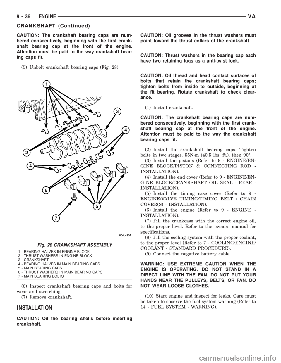
(5) Unbolt crankshaft bearing caps (Fig. 28).
(6) Inspect crankshaft bearing caps and bolts for
wear and stretching.
(7) Remove crankshaft.
INSTALLATION
CAUTION: Oil the bearing shells before inserting
crankshaft.CAUTION: Oil grooves in the thrust washers must
point toward the thrust collars of the crankshaft.
CAUTION: Thrust washers in the bearing cap each
have two retaining lugs as a anti-twist lock.
CAUTION: Oil thread and head contact surfaces of
bolts that retain the crankshaft bearing caps;
tighten bolts from inside to outside, beginning at
the fit bearing. Rotate crankshaft to check clear-
ance.
(1) Install crankshaft.
CAUTION: The crankshaft bearing caps are num-
bered consecutively, beginning with the first crank-
shaft bearing cap at the front of the engine.
Attention must be paid to the way the crankshaft
bearing caps fit.
(2) Install the crankshaft bearing caps. Tighten
bolts in two stages. 55N´m (40.5 lbs. ft.), then 90É.
(3) Install the pistons (Refer to 9 - ENGINE/EN-
GINE BLOCK/PISTON & CONNECTING ROD -
INSTALLATION).
(4) Install the end cover (Refer to 9 - ENGINE/EN-
GINE BLOCK/CRANKSHAFT OIL SEAL - REAR -
INSTALLATION).
(5) Install the timing case cover (Refer to 9 -
ENGINE/VALVE TIMING/TIMING BELT / CHAIN
COVER(S) - INSTALLATION).
(6) Install the engine (Refer to 9 - ENGINE -
INSTALLATION).
(7) Fill the crankcase with the correct engine oil,
to the proper level. Refer to the owners manual for
specifications.
(8) Fill the cooling system with the proper coolant,
to the proper level (Refer to 7 - COOLING/ENGINE/
COOLANT - STANDARD PROCEDURE).
(9) Connect the negative battery cable.
WARNING: USE EXTREME CAUTION WHEN THE
ENGINE IS OPERATING. DO NOT STAND IN A
DIRECT LINE WITH THE FAN. DO NOT PUT YOUR
HANDS NEAR THE PULLEYS, BELTS, OR FAN. DO
NOT WEAR LOOSE CLOTHES.
(10) Start engine and inspect for leaks. Care must
be taken to observe the fuel system warning (Refer to
14 - FUEL SYSTEM - WARNING).
Fig. 28 CRANKSHAFT ASSEMBLY
1 - BEARING HALVES IN ENGINE BLOCK
2 - THRUST WASHERS IN ENGINE BLOCK
3 - CRANKSHAFT
4 - BEARING HALVES IN MAIN BEARING CAPS
5 - MAIN BEARING CAPS
6 - THRUST WASHERS IN MAIN BEARING CAPS
7 - MAIN BEARING BOLTS
9 - 36 ENGINEVA
CRANKSHAFT (Continued)
Page 782 of 1232
CAUTION: Assemble the piston and connecting rod
so that the arrow is pointing in the direction of
travel (in the opposite direction of power flow). The
marking on the connecting rod is pointing toward
the inlet side.
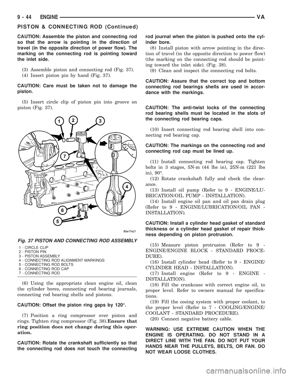
(3) Assemble piston and connecting rod (Fig. 37).
(4) Insert piston pin by hand (Fig. 37).
CAUTION: Care must be taken not to damage the
piston.
(5) Insert circle clip of piston pin into groove on
piston (Fig. 37).
(6) Using the appropriate clean engine oil, clean
the cylinder bores, connecting rod bearing journals,
connecting rod bearing shells and pistons.
CAUTION: Offset the piston ring gaps by 120É.
(7) Position a ring compressor over piston and
rings. Tighten ring compressor (Fig. 38).Ensure that
ring position does not change during this oper-
ation.
CAUTION: Rotate the crankshaft sufficiently so that
the connecting rod does not touch the connectingrod journal when the piston is pushed onto the cyl-
inder bore.
(8) Install piston with arrow pointing in the direc-
tion of travel (in the opposite direction to power flow)
(the marking on the connecting rod should be point-
ing toward the inlet side). (Fig. 38).
(9) Clean and inspect the connecting rod bolts.
CAUTION: Assure that the correct top and bottom
connecting rod bearings shells are used in accor-
dance with the markings.
CAUTION: The anti-twist locks of the connecting
rod bearing shells must be located in the slots of
the connecting rod bearing caps.
(10) Insert connecting rod bearing shell into con-
necting rod bearing cap.
CAUTION: The markings on the connecting rod and
connecting rod cap must be lined up.
(11) Install connecting rod bearing cap. Tighten
bolts in 3 stages, 5N´m (44 lbs in), 25N´m (221 lbs
in), 90É.
(12) Rotate crankshaft fully and check the clear-
ance.
(13) Install oil pump (Refer to 9 - ENGINE/LU-
BRICATION/OIL PUMP - INSTALLATION).
(14) Install engine oil pan and oil pan drain plug
(Refer to 9 - ENGINE/LUBRICATION/OIL PAN -
INSTALLATION).
CAUTION: Install a cylinder head gasket of standard
thickness or a cylinder head gasket of repair thick-
ness depending on piston protrusion.
(15) Measure piston protrusion (Refer to 9 -
ENGINE/ENGINE BLOCK - STANDARD PROCE-
DURE).
(16) Install cylinder head (Refer to 9 - ENGINE/
CYLINDER HEAD - INSTALLATION).
(17) Install engine (Refer to 9 - ENGINE -
INSTALLATION).
(18) Fill the crankcase with correct engine oil, to
proper level. Refer to owners manual for specifica-
tions.
(19) Fill the cooing system with proper coolant, to
the proper level (Refer to 7 - COOLING/ENGINE/
COOLANT - STANDARD PROCEDURE).
(20) Connect negative battery cable.
WARNING: USE EXTREME CAUTION WHEN THE
ENGINE IS OPERATING. DO NOT STAND IN A
DIRECT LINE WITH THE FAN. DO NOT PUT YOUR
HANDS NEAR THE PULLEYS, BELTS, OR FAN. DO
NOT WEAR LOOSE CLOTHES.
Fig. 37 PISTON AND CONNECTING ROD ASSEMBLY
1 - CIRCLE CLIP
2 - PISTON PIN
3 - PISTON ASSEMBLY
4 - CONNECTING ROD ALIGNMENT MARKINGS
5 - CONNECTING ROD BOLTS
6 - CONNECTING ROD CAP
7 - CONNECTING ROD
9 - 44 ENGINEVA
PISTON & CONNECTING ROD (Continued)
Page 788 of 1232
(7) Remove the engine support fixture and adap-
tors.
OIL
REMOVAL - OIL SEPARATOR
(1) Disconnect breather hose.
(2) Remove the separator retaining bolts
(3) Twist to remove oil separator from cover.
INSTALLATION - OIL SEPARATOR
(1) Lubricate the oil separator o - ring with clean
engine oil.
(2) Position separator above cover and apply down-
ward pressure to seat.
(3) Install retaining bolts and tighten to 8N´m (70
lbs. in.).
(4) Connect breather hose.
OIL COOLER & LINES
REMOVAL
WARNING: RISK OF INJURY TO SKIN AND EYES
DUE TO SCALDING FROM HOT COOLANT. DO NOTOPEN THE COOLING SYSTEM UNLESS THE TEM-
PERATURE IS BELOW 194ÉF (90ÉC). WEAR PRO-
TECTIVE CLOTHING AND EYE WEAR. RISK OF
POISONING IF COOLANT IS SWALLOWED. STORE
COOLANT IN PROPER AND APPROPRIATELY
MARKED CONTAINERS.
(1) Drain cooling system.
(2) Remove the oil filter.
(3) Remove the coolant hoses from the oil cooler
(Fig. 47).
(4) Remove the oil cooler from the timing case
cover (Fig. 47).
INSTALLATION
(1) Clean all sealing surfaces.
(2) Install the engine oil cooler to the timing case
cover with a new gasket. Tighten bolts to 14N´m (124
lbs. in.) (Fig. 47).
(3) Reconnect the coolant hoses and tighten
clamps.
(4) Install new oil filter and tighten oil filter cap to
25N´m ( 18 lbs. ft.) (Fig. 47).
(5) Refill cooling system.
(6) Start engine and inspect for leaks.
(7) Turn engine off and check engine oil level. Add
as necessary.
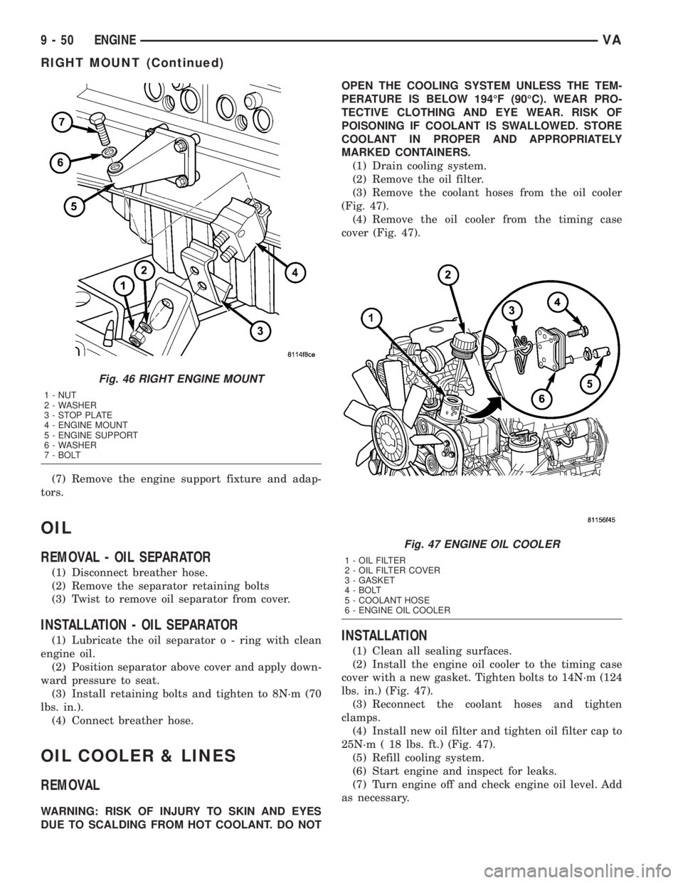
Fig. 46 RIGHT ENGINE MOUNT
1 - NUT
2 - WASHER
3 - STOP PLATE
4 - ENGINE MOUNT
5 - ENGINE SUPPORT
6 - WASHER
7 - BOLT
Fig. 47 ENGINE OIL COOLER
1 - OIL FILTER
2 - OIL FILTER COVER
3 - GASKET
4 - BOLT
5 - COOLANT HOSE
6 - ENGINE OIL COOLER
9 - 50 ENGINEVA
RIGHT MOUNT (Continued)
Page 789 of 1232
OIL FILTER
REMOVAL
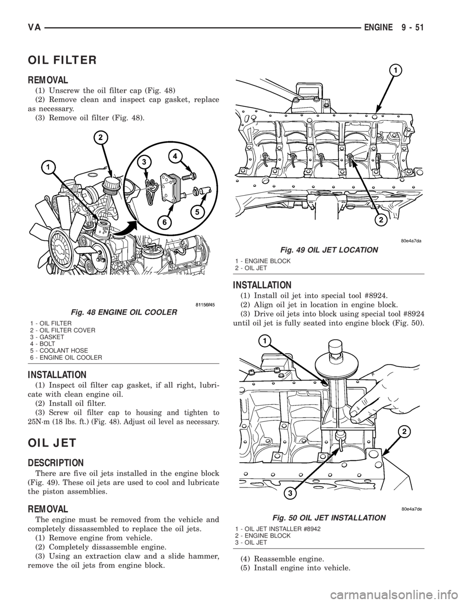
(1) Unscrew the oil filter cap (Fig. 48)
(2) Remove clean and inspect cap gasket, replace
as necessary.
(3) Remove oil filter (Fig. 48).
INSTALLATION
(1) Inspect oil filter cap gasket, if all right, lubri-
cate with clean engine oil.
(2) Install oil filter.
(3)
Screw oil filter cap to housing and tighten to
25N´m (18 lbs. ft.) (Fig. 48). Adjust oil level as necessary.
OIL JET
DESCRIPTION
There are five oil jets installed in the engine block
(Fig. 49). These oil jets are used to cool and lubricate
the piston assemblies.
REMOVAL
The engine must be removed from the vehicle and
completely dissassembled to replace the oil jets.
(1) Remove engine from vehicle.
(2) Completely dissassemble engine.
(3) Using an extraction claw and a slide hammer,
remove the oil jets from engine block.
INSTALLATION
(1) Install oil jet into special tool #8924.
(2) Align oil jet in location in engine block.
(3) Drive oil jets into block using special tool #8924
until oil jet is fully seated into engine block (Fig. 50).
(4) Reassemble engine.
(5) Install engine into vehicle.
Fig. 48 ENGINE OIL COOLER
1 - OIL FILTER
2 - OIL FILTER COVER
3 - GASKET
4 - BOLT
5 - COOLANT HOSE
6 - ENGINE OIL COOLER
Fig. 49 OIL JET LOCATION
1 - ENGINE BLOCK
2 - OIL JET
Fig. 50 OIL JET INSTALLATION
1 - OIL JET INSTALLER #8942
2 - ENGINE BLOCK
3 - OIL JET
VAENGINE 9 - 51
Page 795 of 1232
Oil level and oil quality are separate of each other.
The information is first of all compensated in the
ECM before being transmitted over the CAN bus.
Faults at the oil sensor are detected by the ECM
and entered into fault memory. The voltage for the
oil sensor (approx.5V) is supplied by the ECM.
REMOVAL
(1) Disconnect the negative battery cable.
(2) Raise and support the vehicle.
(3) Drain engine oil into a suitable, and appropri-
ately marked container.
(4) Remove engine mount to chassis nuts.
(5) Lower vehicle and install engine support.
(6) Raise engine until the weight of the engine no
longer rests on the engine mounts.
(7) Raise and support the vehicle.
(8) Detach the front stabilizer bar at the front axle
and rotate it downward.
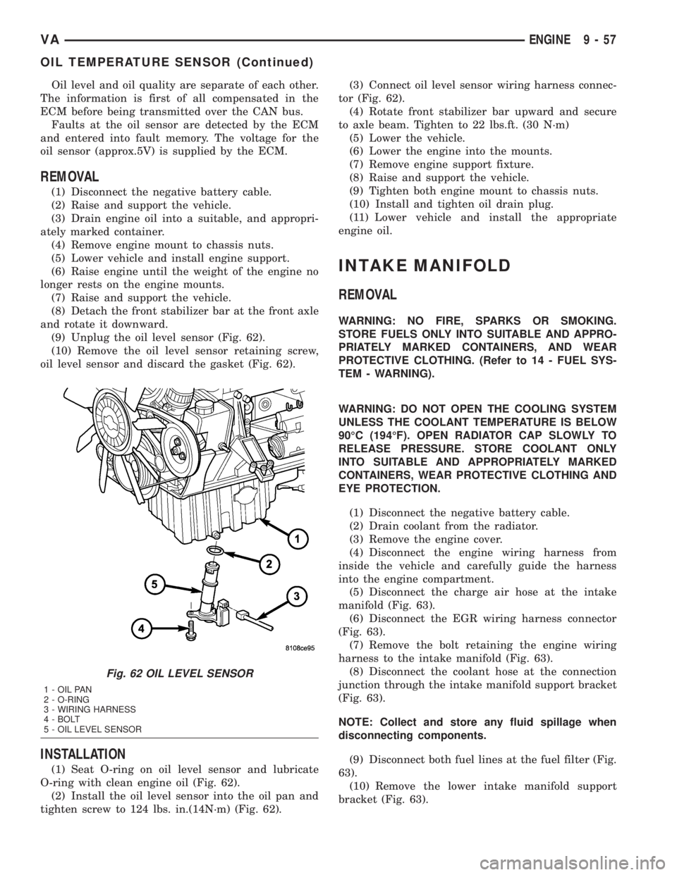
(9) Unplug the oil level sensor (Fig. 62).
(10) Remove the oil level sensor retaining screw,
oil level sensor and discard the gasket (Fig. 62).
INSTALLATION
(1) Seat O-ring on oil level sensor and lubricate
O-ring with clean engine oil (Fig. 62).
(2) Install the oil level sensor into the oil pan and
tighten screw to 124 lbs. in.(14N´m) (Fig. 62).(3) Connect oil level sensor wiring harness connec-
tor (Fig. 62).
(4) Rotate front stabilizer bar upward and secure
to axle beam. Tighten to 22 lbs.ft. (30 N´m)
(5) Lower the vehicle.
(6) Lower the engine into the mounts.
(7) Remove engine support fixture.
(8) Raise and support the vehicle.
(9) Tighten both engine mount to chassis nuts.
(10) Install and tighten oil drain plug.
(11) Lower vehicle and install the appropriate
engine oil.
INTAKE MANIFOLD
REMOVAL
WARNING: NO FIRE, SPARKS OR SMOKING.
STORE FUELS ONLY INTO SUITABLE AND APPRO-
PRIATELY MARKED CONTAINERS, AND WEAR
PROTECTIVE CLOTHING. (Refer to 14 - FUEL SYS-
TEM - WARNING).
WARNING: DO NOT OPEN THE COOLING SYSTEM
UNLESS THE COOLANT TEMPERATURE IS BELOW
90ÉC (194ÉF). OPEN RADIATOR CAP SLOWLY TO
RELEASE PRESSURE. STORE COOLANT ONLY
INTO SUITABLE AND APPROPRIATELY MARKED
CONTAINERS, WEAR PROTECTIVE CLOTHING AND
EYE PROTECTION.
(1) Disconnect the negative battery cable.
(2) Drain coolant from the radiator.
(3) Remove the engine cover.
(4) Disconnect the engine wiring harness from
inside the vehicle and carefully guide the harness
into the engine compartment.
(5) Disconnect the charge air hose at the intake
manifold (Fig. 63).
(6) Disconnect the EGR wiring harness connector
(Fig. 63).
(7) Remove the bolt retaining the engine wiring
harness to the intake manifold (Fig. 63).
(8) Disconnect the coolant hose at the connection
junction through the intake manifold support bracket
(Fig. 63).
NOTE: Collect and store any fluid spillage when
disconnecting components.
(9) Disconnect both fuel lines at the fuel filter (Fig.
63).
(10) Remove the lower intake manifold support
bracket (Fig. 63).
Fig. 62 OIL LEVEL SENSOR
1 - OIL PAN
2 - O-RING
3 - WIRING HARNESS
4 - BOLT
5 - OIL LEVEL SENSOR
VAENGINE 9 - 57
OIL TEMPERATURE SENSOR (Continued)
Page 799 of 1232
(8) Position and install the oil pan. Tighten M6
bolts to 9 N´m (80 lbs in) and M8 bolts to 20 N´m
(177 lbs in).
(9) Install belt /pulley vibration damper. Tighten
M8.8 bolt in two stages, 200N´m (147 lbs ft.) then
90É, M10.9 bolt 325N´m (240 lbs ft) then 90É.
(10) Remove the engine support fixture.
(11) Install generator (Refer to 8 - ELECTRICAL/
CHARGING/GENERATOR - INSTALLATION).
(12) Install the air conditioning compressor.
(13) Install the power steering pump.
(14) Install water pump (Refer to 7 - COOLING/
ENGINE/WATER PUMP - INSTALLATION).
(15) Connect coolant hose to oil-water heat
exchanger.
(16) Install high pressure fuel pump (Refer to 14 -
FUEL SYSTEM/FUEL DELIVERY/FUEL PUMP -
INSTALLATION).
(17) Apply sealant to lower portion of, and install,
front cover to cylinder block. Tighten bolts to 20N´m
(177 lbs in) (Refer to 9 - ENGINE/CYLINDER HEAD
- INSTALLATION).
(18) Remove retaining lock for crankshaft/starter
ring gear.
(19) Tighten the oil drain plug to 30N´m (265 lbs
in).
(20) Install a new oil filter. tighten screw cap for
filter to 25N´m (221 lbs. in.).
(21) Install the accessory drive belt.
(22) Install the radiator assembly (Refer to 7 -
COOLING/ENGINE/RADIATOR - INSTALLATION).(23) Install air intake hose.
(24) Fill coolant to the proper level, with the
proper coolant (Refer to 7 - COOLING/ENGINE/
COOLANT - STANDARD PROCEDURE).
(25) Fill the crankcase with the correct oil, to the
proper level. Refer to owners manual for specifica-
tions.
(26) Connect the negative battery cable.
WARNING: USE EXTREME CAUTION WHEN THE
ENGINE IS OPERATING. DO NOT STAND IN A
DIRECT LINE WITH THE FAN. DO NOT PUT YOUR
HANDS NEAR THE PULLEYS, BELTS OR FAN. DO
NOT WEAR LOOSE CLOTHES.
CAUTION: DO NOT pressure test cooling system
until the engine reaches operating temperature.
(27) Start engine and inspect for leaks. care must
be taken to observe the fuel system warning (Refer to
14 - FUEL SYSTEM - WARNING).
TIMING BELT/CHAIN AND
SPROCKETS
REMOVAL
REMOVAL - TENSIONING AND SLIDE RAILS
NOTE: If it necessary to replace the tensioning rail,
slide rail or tensioning arm, they are always
replaced together.
(1) Disconnect negative battery cable.
(2) Remove the engine (Refer to 9 - ENGINE -
REMOVAL).
(3) Remove cylinder head (Refer to 9 - ENGINE/
CYLINDER HEAD - REMOVAL).
NOTE: Remove timing case cover carefully. Care
must be taken not to damage oil pan gasket.
(4) Remove timing case cover (Refer to 9 -
ENGINE/VALVE TIMING/TIMING BELT / CHAIN
COVER(S) - REMOVAL).
(5) Pull the tensioning rail off of the bearing pins
(Fig. 67).
(6) Release the spring at the slide rail and take it
off of the tensioning arm (Fig. 67).
REMOVAL - INTERMEDIATE GEAR
(1) Disconnect negative battery cable.
(2) Remove engine cover (Refer to 9 - ENGINE -
REMOVAL).
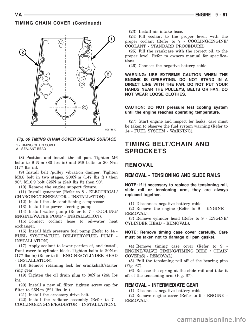
Fig. 66 TIMING CHAIN COVER SEALING SURFACE
1 - TIMING CHAIN COVER
2 - SEALANT BEAD
VAENGINE 9 - 61
TIMING CHAIN COVER (Continued)