2005 MERCEDES-BENZ SPRINTER warning light
[x] Cancel search: warning lightPage 287 of 1232
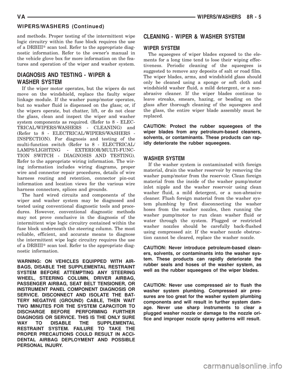
and methods. Proper testing of the intermittent wipe
logic circuitry within the fuse block requires the use
of a DRBIIItscan tool. Refer to the appropriate diag-
nostic information. Refer to the owner's manual in
the vehicle glove box for more information on the fea-
tures and operation of the wiper and washer system.
DIAGNOSIS AND TESTING - WIPER &
WASHER SYSTEM
If the wiper motor operates, but the wipers do not
move on the windshield, replace the faulty wiper
linkage module. If the washer pump/motor operates,
but no washer fluid is dispensed on the glass; or, if
the wipers operate, but chatter, lift, or do not clear
the glass, clean and inspect the wiper and washer
system components as required. (Refer to 8 - ELEC-
TRICAL/WIPERS/WASHERS - CLEANING) and
(Refer to 8 - ELECTRICAL/WIPERS/WASHERS -
INSPECTION). For diagnosis and testing of the
multi-function switch (Refer to 8 - ELECTRICAL/
LAMPS/LIGHTING - EXTERIOR/MULTI-FUNC-
TION SWITCH - DIAGNOSIS AND TESTING).
Refer to the appropriate wiring information. The wir-
ing information includes wiring diagrams, proper
wire and connector repair procedures, details of wire
harness routing and retention, connector pin-out
information and location views for the various wire
harness connectors, splices and grounds.
The hard wired circuits and components of the
wiper and washer system may be diagnosed and
tested using conventional diagnostic tools and proce-
dures. However, conventional diagnostic methods
may not prove conclusive in the diagnosis of the
intermittent wipe logic circuitry contained within the
fuse block underneath the steering column. The most
reliable, efficient, and accurate means to diagnose
the intermittent wipe logic circuitry requires the use
of a DRBIIItscan tool. Refer to the appropriate diag-
nostic information.
WARNING: ON VEHICLES EQUIPPED WITH AIR-
BAGS, DISABLE THE SUPPLEMENTAL RESTRAINT
SYSTEM BEFORE ATTEMPTING ANY STEERING
WHEEL, STEERING COLUMN, DRIVER AIRBAG,
PASSENGER AIRBAG, SEAT BELT TENSIONER, OR
INSTRUMENT PANEL COMPONENT DIAGNOSIS OR
SERVICE. DISCONNECT AND ISOLATE THE BAT-
TERY NEGATIVE (GROUND) CABLE, THEN WAIT
TWO MINUTES FOR THE SYSTEM CAPACITOR TO
DISCHARGE BEFORE PERFORMING FURTHER
DIAGNOSIS OR SERVICE. THIS IS THE ONLY SURE
WAY TO DISABLE THE SUPPLEMENTAL
RESTRAINT SYSTEM. FAILURE TO TAKE THE
PROPER PRECAUTIONS COULD RESULT IN ACCI-
DENTAL AIRBAG DEPLOYMENT AND POSSIBLE
PERSONAL INJURY.
CLEANING - WIPER & WASHER SYSTEM
WIPER SYSTEM
The squeegees of wiper blades exposed to the ele-
ments for a long time tend to lose their wiping effec-
tiveness. Periodic cleaning of the squeegees is
suggested to remove any deposits of salt or road film.
The wiper blades, arms, and windshield glass should
only be cleaned using a sponge or soft cloth and
windshield washer fluid, a mild detergent, or a non-
abrasive cleaner. If the wiper blades continue to
leave streaks, smears, hazing, or beading on the
glass after thorough cleaning of the squeegees and
the glass, the entire wiper blade assembly must be
replaced.
CAUTION: Protect the rubber squeegees of the
wiper blades from any petroleum-based cleaners,
solvents, or contaminants. These products can rap-
idly deteriorate the rubber squeegees.
WASHER SYSTEM
If the washer system is contaminated with foreign
material, drain the washer reservoir by removing the
washer pump/motor from the reservoir. Clean foreign
material from the inside of the washer pump/motor
inlet nipple and the washer reservoir using clean
washer fluid, a mild detergent, or a non-abrasive
cleaner. Flush foreign material from the washer sys-
tem plumbing by first disconnecting the washer
hoses from the washer nozzles, then running the
washer pump/motor to run clean washer fluid or
water through the system. Plugged or restricted
washer nozzles should be carefully back-flushed
using compressed air. If the washer nozzle obstruc-
tion cannot be cleared, replace the washer nozzle.
CAUTION: Never introduce petroleum-based clean-
ers, solvents, or contaminants into the washer sys-
tem. These products can rapidly deteriorate the
rubber seals and hoses of the washer system, as
well as the rubber squeegees of the wiper blades.
CAUTION: Never use compressed air to flush the
washer system plumbing. Compressed air pres-
sures are too great for the washer system plumbing
components and will result in further system dam-
age. Never use sharp instruments to clear a
plugged washer nozzle or damage to the nozzle ori-
fice and improper nozzle spray patterns will result.
VAWIPERS/WASHERS 8R - 5
WIPERS/WASHERS (Continued)
Page 317 of 1232
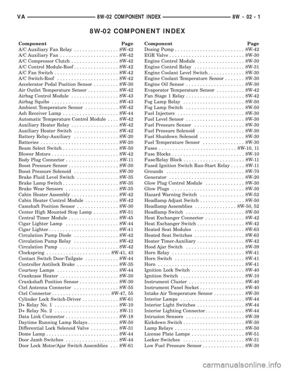
8W-02 COMPONENT INDEX
Component Page
A/C Auxiliary Fan Relay................ 8W-42
A/C Auxiliary Fan..................... 8W-42
A/C Compressor Clutch................. 8W-42
A/C Control Module-Roof................ 8W-42
A/C Fan Switch....................... 8W-42
A/C Switch-Roof...................... 8W-42
Accelerator Pedal Position Sensor......... 8W-30
Air Outlet Temperature Sensor........... 8W-42
Airbag Control Module................. 8W-43
Airbag Squibs........................ 8W-43
Ambient Temperature Sensor............ 8W-42
Ash Receiver Lamp.................... 8W-44
Automatic Temperature Control Module.... 8W-42
Auxiliary Heater Relay................. 8W-42
Auxiliary Heater Switch................ 8W-42
Battery Relay-Auxiliary................ 8W-20
Batteries............................ 8W-20
Beam Select Switch.................... 8W-50
Blower Motors........................ 8W-42
Body Plug Connector................... 8W-11
Boost Pressure Sensor.................. 8W-30
Boost Pressure Solenoid................ 8W-30
Brake Fluid Level Switch............... 8W-35
Brake Lamp Switch.................... 8W-35
Brake Wear Sensors................... 8W-35
Cabin Heater Assembly................. 8W-42
Cabin Heater Control Module............ 8W-42
Camshaft Position Sensor............... 8W-30
Center High Mounted Stop Lamp......... 8W-51
Central Timer Module.................. 8W-45
Cigar Lighter Lamp................... 8W-44
Cigar Lighter......................... 8W-41
Circulation Pump Diode................ 8W-42
Circulation Pump Relay................ 8W-42
Circulation Pump..................... 8W-42
Clockspring....................... 8W-41, 43
Contact Switch Door-Tailgate............ 8W-44
Controller Antilock Brake............... 8W-35
Courtesy Lamps...................... 8W-44
Crankcase Heater..................... 8W-30
Crankshaft Position Sensor.............. 8W-30
Ctel Antenna Connector................ 8W-55
Ctel Connector..................... 8W-47, 55
Cylinder Lock Switch-Driver............. 8W-61
D+ Relay No. 1....................... 8W-10
D+ Relay No. 2....................... 8W-11
Data Link Connector................... 8W-18
Daytime Running Lamp Relays........... 8W-50
Differential Lock Solenoid Valve.......... 8W-31
Dome Lamp.......................... 8W-44
Door Jamb Switches................... 8W-44
Door Lock Motor/Ajar Switch Assemblies . . . 8W-61Component Page
Dosing Pump......................... 8W-42
EGR Valve........................... 8W-30
Engine Control Module................. 8W-30
Engine Control Relay.................. 8W-31
Engine Coolant Level Switch............. 8W-30
Engine Coolant Temperature Sensor....... 8W-30
Engine Oil Sensor..................... 8W-30
Evaporator Temperature Sensor.......... 8W-42
Fan Stage 1 Relay..................... 8W-42
Fog Lamp Relay...................... 8W-50
Fog Lamp Switch..................... 8W-50
Fuel Injectors........................ 8W-30
Fuel Level Sensor..................... 8W-30
Fuel Pressure Sensor.................. 8W-30
Fuel Pressure Solenoid................. 8W-30
Fuel Shutdown Solenoid................ 8W-30
Fuel Temperature Sensor............... 8W-30
Fuses............................ 8W-10, 11
Fuse Blocks.......................... 8W-10
Fuse/Relay Block...................... 8W-11
Fused Ignition Switch Run-Start Relay..... 8W-11
Grounds............................ 8W-70
Generator........................... 8W-20
Glow Plug Control Module.............. 8W-30
Glow Plugs.......................... 8W-30
Hazard Warning Switch................ 8W-52
Headlamp Adjust Switch................ 8W-50
Headlamp Assemblies............... 8W-50, 52
Headlamp Switch..................... 8W-50
Heat Exchanger Connector.............. 8W-42
Heat Exchanger Switch................. 8W-42
Heated Seat Modules.................. 8W-63
Heated Seat Switches.................. 8W-63
Heater Timer-Auxiliary................. 8W-42
Hood Ajar Switch..................... 8W-39
Horn Relay.......................... 8W-41
Horn Switch......................... 8W-41
Horn............................... 8W-41
Ignition Lock Switch................... 8W-40
Ignition Switch....................... 8W-10
Instrument Cluster.................... 8W-40
Instrument Panel Socket................ 8W-40
Intake Air Temperature Sensor........... 8W-30
Interior Lamps....................... 8W-44
Interior Light Switches................. 8W-44
Interior Lighting Connector.............. 8W-44
Intrusion Sensors..................... 8W-39
Kickdown Switch...................... 8W-30
Lamp Relays......................... 8W-50
License Plate Lamps................... 8W-51
Locker Switches...................... 8W-31
Low Fuel Pressure Sensor............... 8W-30
VA8W-02 COMPONENT INDEX 8W - 02 - 1
Page 319 of 1232
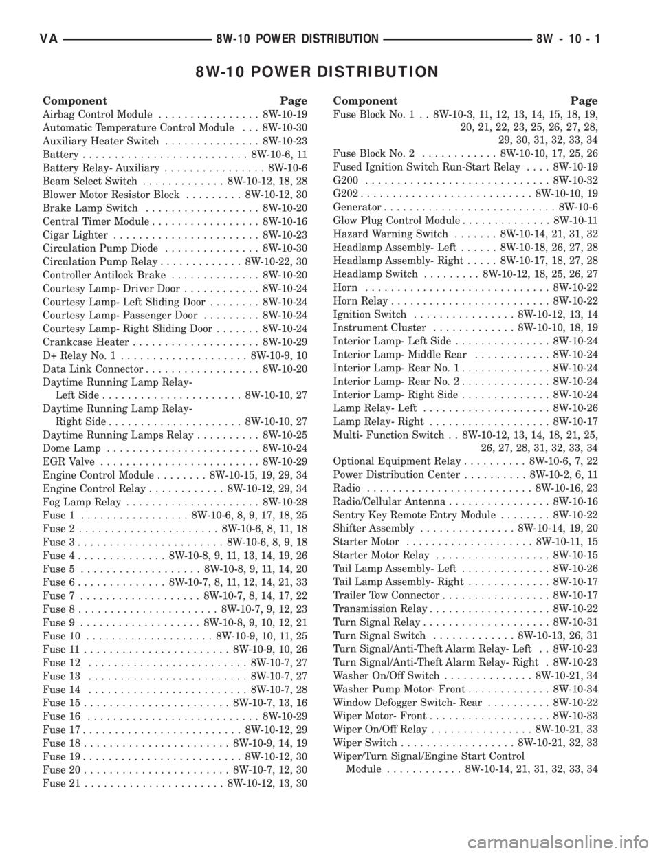
8W-10 POWER DISTRIBUTION
Component Page
Airbag Control Module................ 8W-10-19
Automatic Temperature Control Module . . . 8W-10-30
Auxiliary Heater Switch............... 8W-10-23
Battery.......................... 8W-10-6, 11
Battery Relay- Auxiliary................ 8W-10-6
Beam Select Switch............. 8W-10-12, 18, 28
Blower Motor Resistor Block......... 8W-10-12, 30
Brake Lamp Switch.................. 8W-10-20
Central Timer Module................. 8W-10-16
Cigar Lighter....................... 8W-10-23
Circulation Pump Diode............... 8W-10-30
Circulation Pump Relay............. 8W-10-22, 30
Controller Antilock Brake.............. 8W-10-20
Courtesy Lamp- Driver Door............ 8W-10-24
Courtesy Lamp- Left Sliding Door........ 8W-10-24
Courtesy Lamp- Passenger Door......... 8W-10-24
Courtesy Lamp- Right Sliding Door....... 8W-10-24
Crankcase Heater.................... 8W-10-29
D+ Relay No. 1.................... 8W-10-9, 10
Data Link Connector.................. 8W-10-20
Daytime Running Lamp Relay-
Left Side...................... 8W-10-10, 27
Daytime Running Lamp Relay-
Right Side..................... 8W-10-10, 27
Daytime Running Lamps Relay.......... 8W-10-25
Dome Lamp........................ 8W-10-24
EGR Valve......................... 8W-10-29
Engine Control Module........ 8W-10-15, 19, 29, 34
Engine Control Relay............ 8W-10-12, 29, 34
Fog Lamp Relay..................... 8W-10-28
Fuse 1................. 8W-10-6, 8, 9, 17, 18, 25
Fuse 2...................... 8W-10-6, 8, 11, 18
Fuse 3....................... 8W-10-6, 8, 9, 18
Fuse 4.............. 8W-10-8, 9, 11, 13, 14, 19, 26
Fuse 5................... 8W-10-8, 9, 11, 14, 20
Fuse 6.............. 8W-10-7, 8, 11, 12, 14, 21, 33
Fuse 7................... 8W-10-7, 8, 14, 17, 22
Fuse 8...................... 8W-10-7, 9, 12, 23
Fuse 9................... 8W-10-8, 9, 10, 12, 21
Fuse 10.................... 8W-10-9, 10, 11, 25
Fuse 11....................... 8W-10-9, 10, 26
Fuse 12......................... 8W-10-7, 27
Fuse 13......................... 8W-10-7, 27
Fuse 14......................... 8W-10-7, 28
Fuse 15....................... 8W-10-7, 13, 16
Fuse 16........................... 8W-10-29
Fuse 17......................... 8W-10-12, 29
Fuse 18....................... 8W-10-9, 14, 19
Fuse 19......................... 8W-10-12, 30
Fuse 20....................... 8W-10-7, 12, 30
Fuse 21...................... 8W-10-12, 13, 30
Component Page
Fuse Block No. 1 . . 8W-10-3, 11, 12, 13, 14, 15, 18, 19,
20, 21, 22, 23, 25, 26, 27, 28,
29, 30, 31, 32, 33, 34
Fuse Block No. 2............ 8W-10-10, 17, 25, 26
Fused Ignition Switch Run-Start Relay.... 8W-10-19
G200............................. 8W-10-32
G202........................... 8W-10-10, 19
Generator........................... 8W-10-6
Glow Plug Control Module.............. 8W-10-11
Hazard Warning Switch....... 8W-10-14, 21, 31, 32
Headlamp Assembly- Left...... 8W-10-18, 26, 27, 28
Headlamp Assembly- Right..... 8W-10-17, 18, 27, 28
Headlamp Switch......... 8W-10-12, 18, 25, 26, 27
Horn............................. 8W-10-22
Horn Relay......................... 8W-10-22
Ignition Switch................ 8W-10-12, 13, 14
Instrument Cluster............. 8W-10-10, 18, 19
Interior Lamp- Left Side............... 8W-10-24
Interior Lamp- Middle Rear............ 8W-10-24
Interior Lamp- Rear No. 1.............. 8W-10-24
Interior Lamp- Rear No. 2.............. 8W-10-24
Interior Lamp- Right Side.............. 8W-10-24
Lamp Relay- Left.................... 8W-10-26
Lamp Relay- Right................... 8W-10-17
Multi- Function Switch . . 8W-10-12, 13, 14, 18, 21, 25,
26, 27, 28, 31, 32, 33, 34
Optional Equipment Relay.......... 8W-10-6, 7, 22
Power Distribution Center.......... 8W-10-2, 6, 11
Radio.......................... 8W-10-16, 23
Radio/Cellular Antenna................ 8W-10-16
Sentry Key Remote Entry Module........ 8W-10-22
Shifter Assembly............... 8W-10-14, 19, 20
Starter Motor.................... 8W-10-11, 15
Starter Motor Relay.................. 8W-10-15
Tail Lamp Assembly- Left.............. 8W-10-26
Tail Lamp Assembly- Right............. 8W-10-17
Trailer Tow Connector................. 8W-10-17
Transmission Relay................... 8W-10-22
Turn Signal Relay.................... 8W-10-31
Turn Signal Switch............. 8W-10-13, 26, 31
Turn Signal/Anti-Theft Alarm Relay- Left . . 8W-10-23
Turn Signal/Anti-Theft Alarm Relay- Right . 8W-10-23
Washer On/Off Switch.............. 8W-10-21, 34
Washer Pump Motor- Front............. 8W-10-34
Window Defogger Switch- Rear.......... 8W-10-22
Wiper Motor- Front................... 8W-10-33
Wiper On/Off Relay................ 8W-10-21, 33
Wiper Switch.................. 8W-10-21, 32, 33
Wiper/Turn Signal/Engine Start Control
Module............ 8W-10-14, 21, 31, 32, 33, 34
VA8W-10 POWER DISTRIBUTION 8W - 10 - 1
Page 393 of 1232
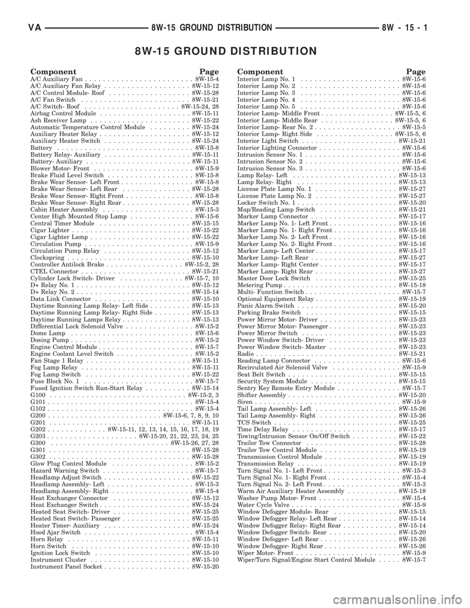
8W-15 GROUND DISTRIBUTION
Component PageA/C Auxiliary Fan........................8W-15-4
A/C Auxiliary Fan Relay...................8W-15-12
A/C Control Module- Roof..................8W-15-28
A/C Fan Switch........................8W-15-21
A/C Switch- Roof.....................8W-15-24, 28
Airbag Control Module....................8W-15-11
Ash Receiver Lamp......................8W-15-22
Automatic Temperature Control Module.........8W-15-24
Auxiliary Heater Relay....................8W-15-12
Auxiliary Heater Switch...................8W-15-24
Battery..............................8W-15-8
Battery Relay- Auxiliary...................8W-15-11
Battery- Auxiliary.......................8W-15-11
Blower Motor- Front......................8W-15-9
Brake Fluid Level Switch...................8W-15-8
Brake Wear Sensor- Left Front................8W-15-8
Brake Wear Sensor- Left Rear...............8W-15-28
Brake Wear Sensor- Right Front...............8W-15-8
Brake Wear Sensor- Right Rear...............8W-15-28
Cabin Heater Assembly....................8W-15-3
Center High Mounted Stop Lamp..............8W-15-6
Central Timer Module....................8W-15-15
Cigar Lighter..........................8W-15-22
Cigar Lighter Lamp......................8W-15-22
Circulation Pump........................8W-15-9
Circulation Pump Relay...................8W-15-12
Clockspring...........................8W-15-10
Controller Antilock Brake.................8W-15-2, 28
CTEL Connector........................8W-15-21
Cylinder Lock Switch- Driver..............8W-15-7, 10
D+ Relay No. 1.........................8W-15-12
D+ Relay No. 2.........................8W-15-14
Data Link Connector.....................8W-15-10
Daytime Running Lamp Relay- Left Side.........8W-15-13
Daytime Running Lamp Relay- Right Side........8W-15-13
Daytime Running Lamps Relay...............8W-15-13
Differential Lock Solenoid Valve...............8W-15-2
Dome Lamp...........................8W-15-6
Dosing Pump...........................8W-15-2
Engine Control Module.....................8W-15-7
Engine Coolant Level Switch.................8W-15-2
Fan Stage 1 Relay.......................8W-15-11
Fog Lamp Relay........................8W-15-11
Fog Lamp Switch.......................8W-15-22
Fuse Block No. 1........................8W-15-7
Fused Ignition Switch Run-Start Relay..........8W-15-14
G100..............................8W-15-2, 3
G101................................8W-15-4
G102................................8W-15-4
G200.........................8W-15-6, 7, 8, 9, 10
G201...............................8W-15-11
G202.............8W-15-11, 12, 13, 14, 15, 16, 17, 18, 19
G203....................8W-15-20, 21, 22, 23, 24, 25
G300..........................8W-15-26, 27, 28
G301...............................8W-15-28
G302...............................8W-15-28
Glow Plug Control Module..................8W-15-2
Hazard Warning Switch....................8W-15-7
Headlamp Adjust Switch...................8W-15-22
Headlamp Assembly- Left...................8W-15-3
Headlamp Assembly- Right..................8W-15-4
Heat Exchanger Connector.................8W-15-12
Heat Exchanger Switch....................8W-15-24
Heated Seat Switch- Driver.................8W-15-25
Heated Seat Switch- Passenger...............8W-15-25
Heater Timer- Auxiliary...................8W-15-24
Hood Ajar Switch........................8W-15-4
Horn Relay...........................8W-15-11
Horn Switch..........................8W-15-10
Ignition Lock Switch.....................8W-15-10
Instrument Cluster......................8W-15-10
Instrument Panel Socket...................8W-15-20Component PageInterior Lamp No. 1......................8W-15-6
Interior Lamp No. 2......................8W-15-6
Interior Lamp No. 3......................8W-15-6
Interior Lamp No. 4......................8W-15-6
Interior Lamp No. 5......................8W-15-6
Interior Lamp- Middle Front................8W-15-5, 6
Interior Lamp- Middle Rear................8W-15-5, 6
Interior Lamp- Rear No. 2...................8W-15-5
Interior Lamp- Right Side.................8W-15-5, 6
Interior Light Switch.....................8W-15-21
Interior Lighting Connector..................8W-15-6
Intrusion Sensor No. 1.....................8W-15-6
Intrusion Sensor No. 2.....................8W-15-6
Intrusion Sensor No. 3.....................8W-15-6
Lamp Relay- Left.......................8W-15-13
Lamp Relay- Right......................8W-15-13
License Plate Lamp No. 1..................8W-15-27
License Plate Lamp No. 2..................8W-15-27
Locker Switch No. 1......................8W-15-20
Map/Reading Lamp Switch.................8W-15-21
Marker Lamp Connector...................8W-15-17
Marker Lamp No. 1- Left Front...............8W-15-16
Marker Lamp No. 1- Right Front..............8W-15-16
Marker Lamp No. 2- Left Front...............8W-15-16
Marker Lamp No. 2- Right Front..............8W-15-16
Marker Lamp- Left Center..................8W-15-17
Marker Lamp- Left Rear...................8W-15-27
Marker Lamp- Right Center.................8W-15-17
Marker Lamp- Right Rear..................8W-15-27
Master Door Lock Switch..................8W-15-25
Metering Pump.........................8W-15-18
Multi- Function Switch.....................8W-15-7
Optional Equipment Relay..................8W-15-19
Panic Alarm Switch......................8W-15-20
Parking Brake Switch....................8W-15-15
Power Mirror Motor- Driver.................8W-15-23
Power Mirror Motor- Passenger...............8W-15-23
Power Mirror Switch.....................8W-15-23
Power Window Switch- Driver...............8W-15-23
Power Window Switch- Master...............8W-15-23
Radio...............................8W-15-21
Reading Lamp Connector...................8W-15-6
Recirculated Air Solenoid Valve...............8W-15-9
Seat Belt Switch........................8W-15-15
Security System Module...................8W-15-15
Sentry Key Remote Entry Module..............8W-15-7
Shifter Assembly........................8W-15-20
Siren................................8W-15-9
Tail Lamp Assembly- Left..................8W-15-26
Tail Lamp Assembly- Right.................8W-15-26
TCS Switch...........................8W-15-25
Time Delay Relay.......................8W-15-17
Towing/Intrusion Sensor On/Off Switch..........8W-15-22
Trailer Tow Connector....................8W-15-28
Trailer Tow Control Module.................8W-15-19
Transmission Control Module................8W-15-19
Transmission Relay......................8W-15-19
Turn Signal No. 1- Left Front.................8W-15-3
Turn Signal No. 1- Right Front................8W-15-4
Turn Signal No. 2- Left Front.................8W-15-3
Warm Air Auxiliary Heater Assembly...........8W-15-18
Washer Pump Motor- Front..................8W-15-4
Water Cycle Valve........................8W-15-9
Window Defogger Module- Rear..............8W-15-15
Window Defogger Relay- Left Rear.............8W-15-14
Window Defogger Relay- Right Rear............8W-15-14
Window Defogger Switch- Rear...............8W-15-20
Window Defogger- Left Rear.................8W-15-26
Window Defogger- Right Rear................8W-15-26
Wiper Motor- Front.......................8W-15-9
Wiper/Turn Signal/Engine Start Control Module.....8W-15-7
VA8W-15 GROUND DISTRIBUTION 8W - 15 - 1
Page 561 of 1232
8W-50 FRONT LIGHTING
Component Page
Beam Select Switch.................. 8W-50-6
D+ Relay No. 1........... 8W-50-7, 8, 12, 14, 15
Daytime Running Lamp Relay- Left Side . . 8W-50-7
Daytime Running Lamp Relay- Right
Side.......................... 8W-50-6, 8
Daytime Running Lamps Relay...... 8W-50-3, 13
Fog Lamp Relay................ 8W-50-6, 9, 10
Fog Lamp Switch.................... 8W-50-9
Fuse 1........................ 8W-50-3, 4, 13
Fuse 2.......................... 8W-50-6, 8
Fuse 3........................ 8W-50-6, 7, 12
Fuse 4....................... 8W-50-3, 14, 15
Fuse 5............................ 8W-50-9
Fuse 6............................ 8W-50-2
Fuse 9................... 8W-50-12, 13, 14, 15
Fuse 10.......................... 8W-50-3, 4
Fuse 11........................ 8W-50-4, 7, 8
Fuse 12.......................... 8W-50-6, 8
Fuse 13........................ 8W-50-6, 7, 8
Fuse 14......................... 8W-50-6, 10
Fuse Block No. 1............... 8W-50-2, 4, 5, 6
Fuse Block No. 2..... 8W-50-3, 7, 8, 12, 13, 14, 15
Fuse Block No. 3.................... 8W-50-9
G100........................... 8W-50-7, 10
G102........................... 8W-50-8, 10
G200.............................. 8W-50-2
G202............. 8W-50-7, 8, 10, 11, 13, 14, 15
G203.............................. 8W-50-9Component Page
Hazard Warning Switch............... 8W-50-2
Headlamp Adjust Switch.......... 8W-50-7, 8, 9
Headlamp Assembly-
Left......... 8W-50-3, 4, 6, 7, 9, 10, 11, 13, 14
Headlamp Assembly-
Right........ 8W-50-3, 4, 6, 8, 9, 10, 11, 13, 15
Headlamp Switch................ 8W-50-4, 5, 6
Lamp Relay- Left............... 8W-50-3, 4, 14
Lamp Relay- Right.............. 8W-50-3, 4, 15
Marker Lamp Connector.............. 8W-50-11
Marker Lamp No. 1- Left Front........ 8W-50-11
Marker Lamp No. 1- Right Front....... 8W-50-11
Marker Lamp No. 2- Left Front........ 8W-50-11
Marker Lamp No. 2- Right Front....... 8W-50-11
Marker Lamp- Left Center............ 8W-50-11
Marker Lamp- Left Rear............. 8W-50-11
Marker Lamp- Right Center........... 8W-50-11
Marker Lamp- Right Rear............ 8W-50-11
Multi- Function Switch.......... 8W-50-2, 4, 5, 6
Power Distribution Center............ 8W-50-12
Tail Lamp Assembly- Left............. 8W-50-14
Tail Lamp Assembly- Right........... 8W-50-15
Turn Signal Relay.................. 8W-50-2, 5
Turn Signal Switch................. 8W-50-4, 5
Wiper/Turn Signal/Engine Start Control
Module........................ 8W-50-2, 5
VA8W-50 FRONT LIGHTING 8W - 50 - 1
Page 787 of 1232
INSTALLATION
(1) Clean all sealing surfaces.
(2) Position driver on rear of pump and install vac-
uum pump with new seals. Tighten bolts to 14N´m
(124 lbs. in.). (Fig. 44)
(3) Install vacuum line to vacuum pump (Fig. 44).
(4) Connect negative battery cable.
WARNING: USE EXTREME CAUTION WHEN THE
ENGINE IS OPERATING. DO NOT STAND IN A
DIRECT LINE WITH THE FAN. DO NOT PUT YOUR
HANDS NEAR THE PULLEYS, BELTS OR FAN. DO
NOT WEAR LOOSE CLOTHES.
(5) Start the engine and inspect for leaks.
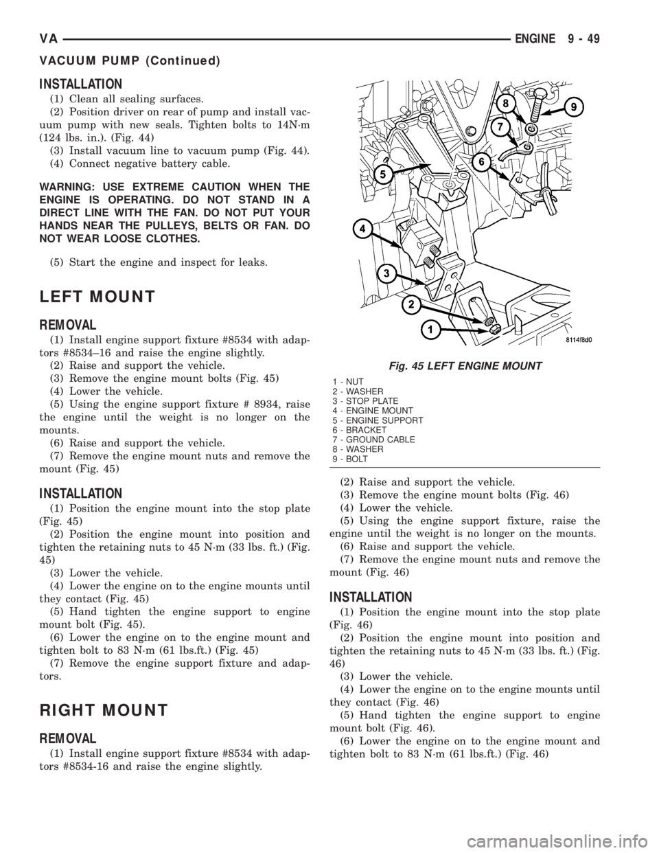
LEFT MOUNT
REMOVAL
(1) Install engine support fixture #8534 with adap-
tors #8534±16 and raise the engine slightly.
(2) Raise and support the vehicle.
(3) Remove the engine mount bolts (Fig. 45)
(4) Lower the vehicle.
(5) Using the engine support fixture # 8934, raise
the engine until the weight is no longer on the
mounts.
(6) Raise and support the vehicle.
(7) Remove the engine mount nuts and remove the
mount (Fig. 45)
INSTALLATION
(1) Position the engine mount into the stop plate
(Fig. 45)
(2) Position the engine mount into position and
tighten the retaining nuts to 45 N´m (33 lbs. ft.) (Fig.
45)
(3) Lower the vehicle.
(4) Lower the engine on to the engine mounts until
they contact (Fig. 45)
(5) Hand tighten the engine support to engine
mount bolt (Fig. 45).
(6) Lower the engine on to the engine mount and
tighten bolt to 83 N´m (61 lbs.ft.) (Fig. 45)
(7) Remove the engine support fixture and adap-
tors.
RIGHT MOUNT
REMOVAL
(1) Install engine support fixture #8534 with adap-
tors #8534-16 and raise the engine slightly.(2) Raise and support the vehicle.
(3) Remove the engine mount bolts (Fig. 46)
(4) Lower the vehicle.
(5) Using the engine support fixture, raise the
engine until the weight is no longer on the mounts.
(6) Raise and support the vehicle.
(7) Remove the engine mount nuts and remove the
mount (Fig. 46)
INSTALLATION
(1) Position the engine mount into the stop plate
(Fig. 46)
(2) Position the engine mount into position and
tighten the retaining nuts to 45 N´m (33 lbs. ft.) (Fig.
46)
(3) Lower the vehicle.
(4) Lower the engine on to the engine mounts until
they contact (Fig. 46)
(5) Hand tighten the engine support to engine
mount bolt (Fig. 46).
(6) Lower the engine on to the engine mount and
tighten bolt to 83 N´m (61 lbs.ft.) (Fig. 46)
Fig. 45 LEFT ENGINE MOUNT
1 - NUT
2 - WASHER
3 - STOP PLATE
4 - ENGINE MOUNT
5 - ENGINE SUPPORT
6 - BRACKET
7 - GROUND CABLE
8 - WASHER
9 - BOLT
VAENGINE 9 - 49
VACUUM PUMP (Continued)
Page 848 of 1232
CRANKSHAFT POSITION
SENSOR
DESCRIPTION
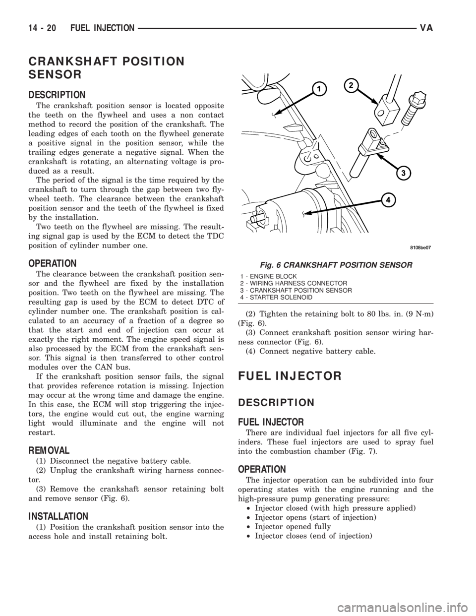
The crankshaft position sensor is located opposite
the teeth on the flywheel and uses a non contact
method to record the position of the crankshaft. The
leading edges of each tooth on the flywheel generate
a positive signal in the position sensor, while the
trailing edges generate a negative signal. When the
crankshaft is rotating, an alternating voltage is pro-
duced as a result.
The period of the signal is the time required by the
crankshaft to turn through the gap between two fly-
wheel teeth. The clearance between the crankshaft
position sensor and the teeth of the flywheel is fixed
by the installation.
Two teeth on the flywheel are missing. The result-
ing signal gap is used by the ECM to detect the TDC
position of cylinder number one.
OPERATION
The clearance between the crankshaft position sen-
sor and the flywheel are fixed by the installation
position. Two teeth on the flywheel are missing. The
resulting gap is used by the ECM to detect DTC of
cylinder number one. The crankshaft position is cal-
culated to an accuracy of a fraction of a degree so
that the start and end of injection can occur at
exactly the right moment. The engine speed signal is
also processed by the ECM from the crankshaft sen-
sor. This signal is then transferred to other control
modules over the CAN bus.
If the crankshaft position sensor fails, the signal
that provides reference rotation is missing. Injection
may occur at the wrong time and damage the engine.
In this case, the ECM will stop triggering the injec-
tors, the engine would cut out, the engine warning
light would illuminate and the engine will not
restart.
REMOVAL
(1) Disconnect the negative battery cable.
(2) Unplug the crankshaft wiring harness connec-
tor.
(3) Remove the crankshaft sensor retaining bolt
and remove sensor (Fig. 6).
INSTALLATION
(1) Position the crankshaft position sensor into the
access hole and install retaining bolt.(2) Tighten the retaining bolt to 80 lbs. in. (9 N´m)
(Fig. 6).
(3) Connect crankshaft position sensor wiring har-
ness connector (Fig. 6).
(4) Connect negative battery cable.
FUEL INJECTOR
DESCRIPTION
FUEL INJECTOR
There are individual fuel injectors for all five cyl-
inders. These fuel injectors are used to spray fuel
into the combustion chamber (Fig. 7).
OPERATION
The injector operation can be subdivided into four
operating states with the engine running and the
high-pressure pump generating pressure:
²Injector closed (with high pressure applied)
²Injector opens (start of injection)
²Injector opened fully
²Injector closes (end of injection)
Fig. 6 CRANKSHAFT POSITION SENSOR
1 - ENGINE BLOCK
2 - WIRING HARNESS CONNECTOR
3 - CRANKSHAFT POSITION SENSOR
4 - STARTER SOLENOID
14 - 20 FUEL INJECTIONVA
Page 855 of 1232
INSTALLATION
(1) (Refer to 14 - FUEL SYSTEM/FUEL INJEC-
TION - WARNING) Install the sealing ring on to the
sensor (Fig. 13).
(2) Screw the sensor in to the fuel rail. Counter-
hold the threaded connection and tighten the sensor
to 18 lbs. ft. (25 N´m.) (Fig. 13).
(3) Connect the wiring harness to the sensor.
(4) Install the mixing housing.
(5) Connect negative battery cable.
FUEL PRESSURE SOLENOID
DESCRIPTION
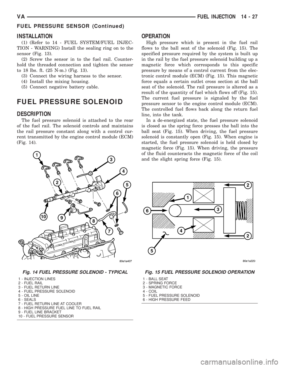
The fuel pressure solenoid is attached to the rear
of the fuel rail. The solenoid controls and maintains
the rail pressure constant along with a control cur-
rent transmitted by the engine control module (ECM)
(Fig. 14).
OPERATION
High pressure which is present in the fuel rail
flows to the ball seat of the solenoid (Fig. 15). The
specified pressure required by the system is built up
in the rail by the fuel pressure solenoid building up a
magnetic force which corresponds to this specific
pressure by means of a control current from the elec-
tronic control module (ECM) (Fig. 15). This magnetic
force equals a certain outlet cross section at the ball
seat of the solenoid. The rail pressure is altered as a
result of the quantity of fuel which flows off (Fig. 15).
The current fuel pressure is signaled by the fuel
pressure sensor to the engine control module (ECM).
The controlled fuel flows back along the return fuel
line, into the tank.
In a de-energized state, the fuel pressure solenoid
is closed as the spring force presses the ball into the
ball seat (Fig. 15). When driving, the fuel pressure
solenoid is constantly open (Fig. 15). When engine is
started, the fuel pressure solenoid is held closed by
magnetic force (Fig. 15). When driving, the pressure
of the fluid counteracts the magnetic force of the coil
and the slight spring force (Fig. 15).
Fig. 14 FUEL PRESSURE SOLENOID - TYPICAL
1 - INJECTION LINES
2 - FUEL RAIL
3 - FUEL RETURN LINE
4 - FUEL PRESSURE SOLENOID
5 - OIL LINE
6 - SEALS
7 - FUEL RETURN LINE AT COOLER
8 - HIGH PRESSURE FUEL LINE TO FUEL RAIL
9 - FUEL LINE BRACKET
10 - FUEL PRESSURE SENSOR
Fig. 15 FUEL PRESSURE SOLENOID OPERATION
1 - BALL SEAT
2 - SPRING FORCE
3 - MAGNETIC FORCE
4 - COIL
5 - FUEL PRESSURE SOLENOID
6 - HIGH PRESSURE FEED
VAFUEL INJECTION 14 - 27
FUEL PRESSURE SENSOR (Continued)