2005 MERCEDES-BENZ SPRINTER low beam
[x] Cancel search: low beamPage 664 of 1232
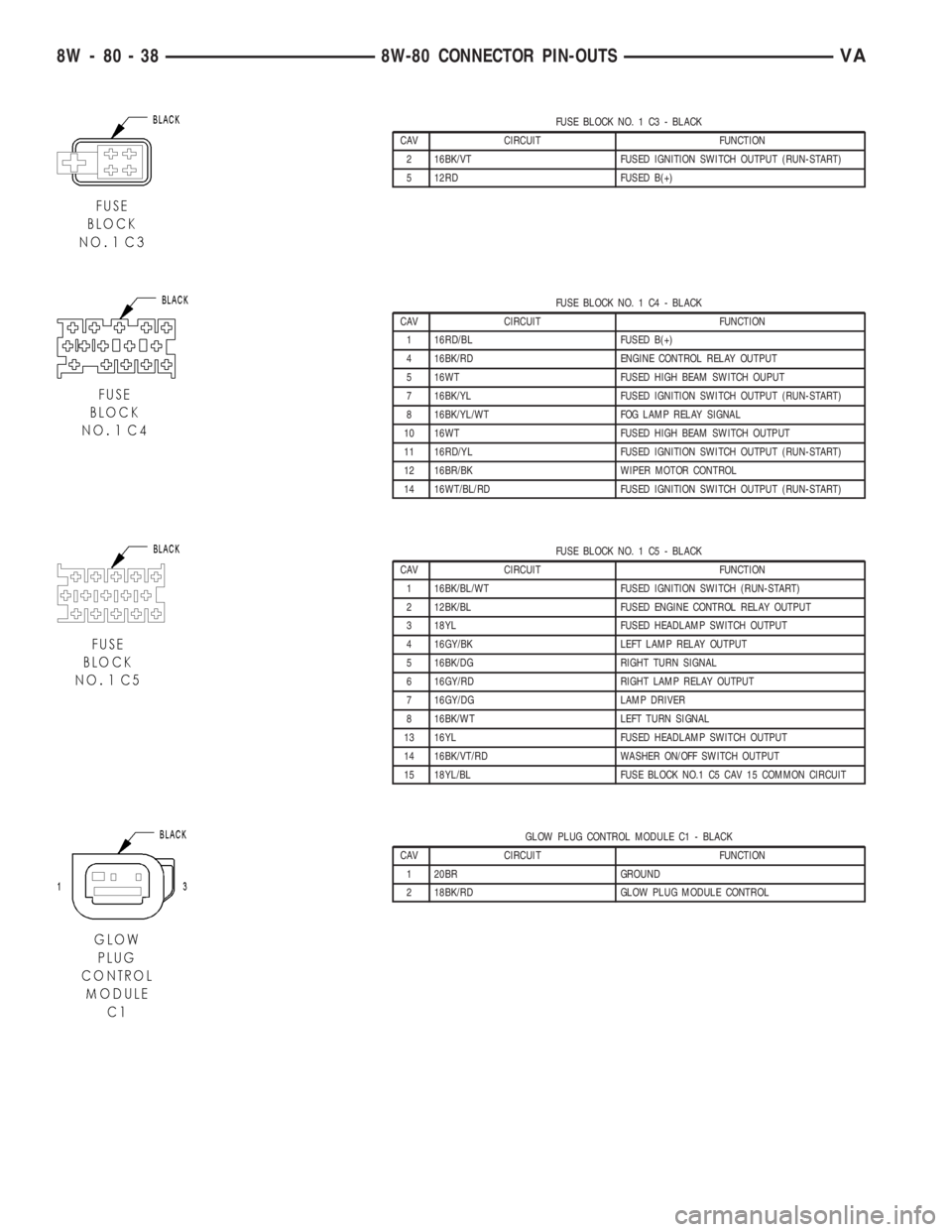
FUSE BLOCK NO. 1 C3 - BLACK
CAV CIRCUIT FUNCTION
2 16BK/VT FUSED IGNITION SWITCH OUTPUT (RUN-START)
5 12RD FUSED B(+)
FUSE BLOCK NO. 1 C4 - BLACK
CAV CIRCUIT FUNCTION
1 16RD/BL FUSED B(+)
4 16BK/RD ENGINE CONTROL RELAY OUTPUT
5 16WT FUSED HIGH BEAM SWITCH OUPUT
7 16BK/YL FUSED IGNITION SWITCH OUTPUT (RUN-START)
8 16BK/YL/WT FOG LAMP RELAY SIGNAL
10 16WT FUSED HIGH BEAM SWITCH OUTPUT
11 16RD/YL FUSED IGNITION SWITCH OUTPUT (RUN-START)
12 16BR/BK WIPER MOTOR CONTROL
14 16WT/BL/RD FUSED IGNITION SWITCH OUTPUT (RUN-START)
FUSE BLOCK NO. 1 C5 - BLACK
CAV CIRCUIT FUNCTION
1 16BK/BL/WT FUSED IGNITION SWITCH (RUN-START)
2 12BK/BL FUSED ENGINE CONTROL RELAY OUTPUT
3 18YL FUSED HEADLAMP SWITCH OUTPUT
4 16GY/BK LEFT LAMP RELAY OUTPUT
5 16BK/DG RIGHT TURN SIGNAL
6 16GY/RD RIGHT LAMP RELAY OUTPUT
7 16GY/DG LAMP DRIVER
8 16BK/WT LEFT TURN SIGNAL
13 16YL FUSED HEADLAMP SWITCH OUTPUT
14 16BK/VT/RD WASHER ON/OFF SWITCH OUTPUT
15 18YL/BL FUSE BLOCK NO.1 C5 CAV 15 COMMON CIRCUIT
GLOW PLUG CONTROL MODULE C1 - BLACK
CAV CIRCUIT FUNCTION
1 20BR GROUND
2 18BK/RD GLOW PLUG MODULE CONTROL
8W - 80 - 38 8W-80 CONNECTOR PIN-OUTSVA
Page 665 of 1232
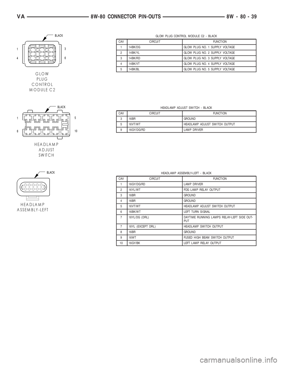
GLOW PLUG CONTROL MODULE C2 - BLACK
CAV CIRCUIT FUNCTION
1 14BK/DG GLOW PLUG NO. 1 SUPPLY VOLTAGE
2 14BK/YL GLOW PLUG NO. 2 SUPPLY VOLTAGE
3 14BK/RD GLOW PLUG NO. 3 SUPPLY VOLTAGE
4 14BK/VT GLOW PLUG NO. 4 SUPPLY VOLTAGE
5 14BK/BL GLOW PLUG NO. 5 SUPPLY VOLTAGE
HEADLAMP ADJUST SWITCH - BLACK
CAV CIRCUIT FUNCTION
3 16BR GROUND
5 16VT/WT HEADLAMP ADJUST SWITCH OUTPUT
9 16GY/DG/RD LAMP DRIVER
HEADLAMP ASSEMBLY-LEFT - BLACK
CAV CIRCUIT FUNCTION
1 16GY/DG/RD LAMP DRIVER
2 16YL/WT FOG LAMP RELAY OUTPUT
3 16BR GROUND
4 16BR GROUND
5 16VT/WT HEADLAMP ADJUST SWITCH OUTPUT
6 16BK/WT LEFT TURN SIGNAL
7 18YL/DG (DRL) DAYTIME RUNNING LAMPS RELAY-LEFT SIDE OUT-
PUT
7 18YL (EXCEPT DRL) HEADLAMP SWITCH OUTPUT
8 16BR GROUND
9 16WT FUSED HIGH BEAM SWITCH OUTPUT
10 16GY/BK LEFT LAMP RELAY OUTPUT
VA8W-80 CONNECTOR PIN-OUTS 8W - 80 - 39
Page 666 of 1232
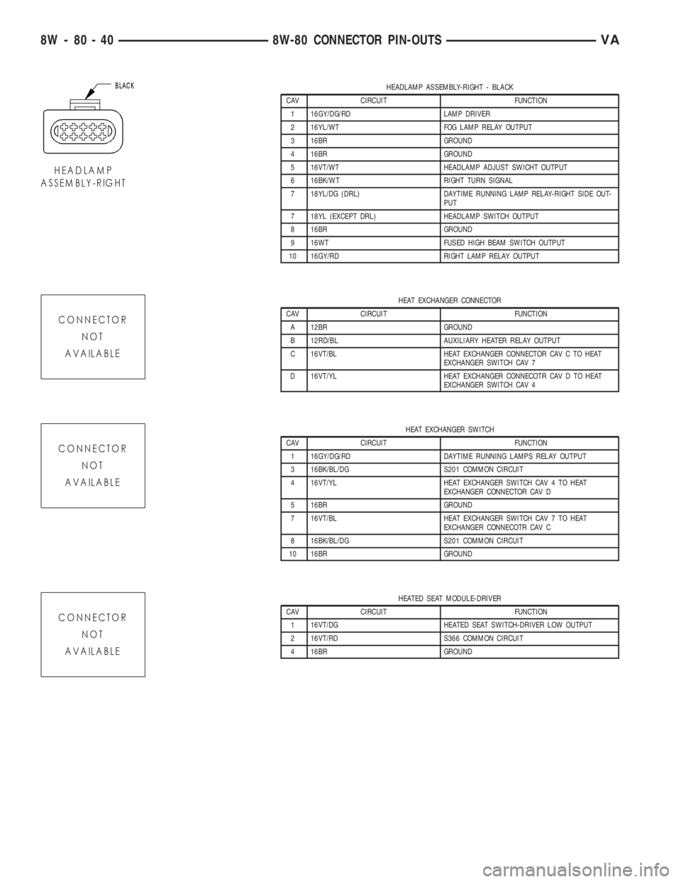
HEADLAMP ASSEMBLY-RIGHT - BLACK
CAV CIRCUIT FUNCTION
1 16GY/DG/RD LAMP DRIVER
2 16YL/WT FOG LAMP RELAY OUTPUT
3 16BR GROUND
4 16BR GROUND
5 16VT/WT HEADLAMP ADJUST SWICHT OUTPUT
6 16BK/WT RIGHT TURN SIGNAL
7 18YL/DG (DRL) DAYTIME RUNNING LAMP RELAY-RIGHT SIDE OUT-
PUT
7 18YL (EXCEPT DRL) HEADLAMP SWITCH OUTPUT
8 16BR GROUND
9 16WT FUSED HIGH BEAM SWITCH OUTPUT
10 16GY/RD RIGHT LAMP RELAY OUTPUT
HEAT EXCHANGER CONNECTOR
CAV CIRCUIT FUNCTION
A 12BR GROUND
B 12RD/BL AUXILIARY HEATER RELAY OUTPUT
C 16VT/BL HEAT EXCHANGER CONNECTOR CAV C TO HEAT
EXCHANGER SWITCH CAV 7
D 16VT/YL HEAT EXCHANGER CONNECOTR CAV D TO HEAT
EXCHANGER SWITCH CAV 4
HEAT EXCHANGER SWITCH
CAV CIRCUIT FUNCTION
1 16GY/DG/RD DAYTIME RUNNING LAMPS RELAY OUTPUT
3 16BK/BL/DG S201 COMMON CIRCUIT
4 16VT/YL HEAT EXCHANGER SWITCH CAV 4 TO HEAT
EXCHANGER CONNECTOR CAV D
5 16BR GROUND
7 16VT/BL HEAT EXCHANGER SWITCH CAV 7 TO HEAT
EXCHANGER CONNECOTR CAV C
8 16BK/BL/DG S201 COMMON CIRCUIT
10 16BR GROUND
HEATED SEAT MODULE-DRIVER
CAV CIRCUIT FUNCTION
1 16VT/DG HEATED SEAT SWITCH-DRIVER LOW OUTPUT
2 16VT/RD S366 COMMON CIRCUIT
4 16BR GROUND
8W - 80 - 40 8W-80 CONNECTOR PIN-OUTSVA
Page 795 of 1232
Oil level and oil quality are separate of each other.
The information is first of all compensated in the
ECM before being transmitted over the CAN bus.
Faults at the oil sensor are detected by the ECM
and entered into fault memory. The voltage for the
oil sensor (approx.5V) is supplied by the ECM.
REMOVAL
(1) Disconnect the negative battery cable.
(2) Raise and support the vehicle.
(3) Drain engine oil into a suitable, and appropri-
ately marked container.
(4) Remove engine mount to chassis nuts.
(5) Lower vehicle and install engine support.
(6) Raise engine until the weight of the engine no
longer rests on the engine mounts.
(7) Raise and support the vehicle.
(8) Detach the front stabilizer bar at the front axle
and rotate it downward.
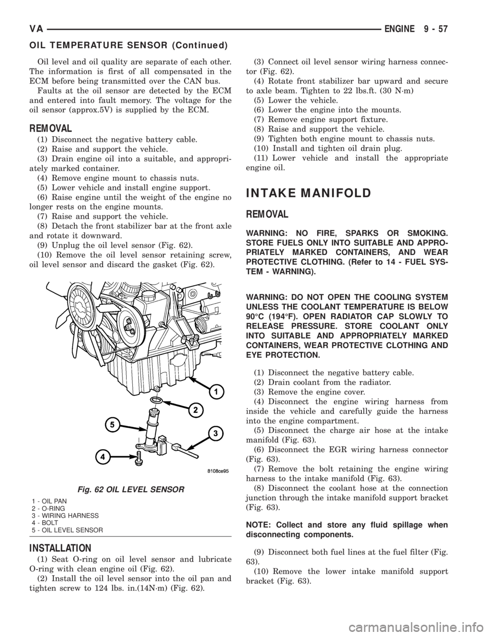
(9) Unplug the oil level sensor (Fig. 62).
(10) Remove the oil level sensor retaining screw,
oil level sensor and discard the gasket (Fig. 62).
INSTALLATION
(1) Seat O-ring on oil level sensor and lubricate
O-ring with clean engine oil (Fig. 62).
(2) Install the oil level sensor into the oil pan and
tighten screw to 124 lbs. in.(14N´m) (Fig. 62).(3) Connect oil level sensor wiring harness connec-
tor (Fig. 62).
(4) Rotate front stabilizer bar upward and secure
to axle beam. Tighten to 22 lbs.ft. (30 N´m)
(5) Lower the vehicle.
(6) Lower the engine into the mounts.
(7) Remove engine support fixture.
(8) Raise and support the vehicle.
(9) Tighten both engine mount to chassis nuts.
(10) Install and tighten oil drain plug.
(11) Lower vehicle and install the appropriate
engine oil.
INTAKE MANIFOLD
REMOVAL
WARNING: NO FIRE, SPARKS OR SMOKING.
STORE FUELS ONLY INTO SUITABLE AND APPRO-
PRIATELY MARKED CONTAINERS, AND WEAR
PROTECTIVE CLOTHING. (Refer to 14 - FUEL SYS-
TEM - WARNING).
WARNING: DO NOT OPEN THE COOLING SYSTEM
UNLESS THE COOLANT TEMPERATURE IS BELOW
90ÉC (194ÉF). OPEN RADIATOR CAP SLOWLY TO
RELEASE PRESSURE. STORE COOLANT ONLY
INTO SUITABLE AND APPROPRIATELY MARKED
CONTAINERS, WEAR PROTECTIVE CLOTHING AND
EYE PROTECTION.
(1) Disconnect the negative battery cable.
(2) Drain coolant from the radiator.
(3) Remove the engine cover.
(4) Disconnect the engine wiring harness from
inside the vehicle and carefully guide the harness
into the engine compartment.
(5) Disconnect the charge air hose at the intake
manifold (Fig. 63).
(6) Disconnect the EGR wiring harness connector
(Fig. 63).
(7) Remove the bolt retaining the engine wiring
harness to the intake manifold (Fig. 63).
(8) Disconnect the coolant hose at the connection
junction through the intake manifold support bracket
(Fig. 63).
NOTE: Collect and store any fluid spillage when
disconnecting components.
(9) Disconnect both fuel lines at the fuel filter (Fig.
63).
(10) Remove the lower intake manifold support
bracket (Fig. 63).
Fig. 62 OIL LEVEL SENSOR
1 - OIL PAN
2 - O-RING
3 - WIRING HARNESS
4 - BOLT
5 - OIL LEVEL SENSOR
VAENGINE 9 - 57
OIL TEMPERATURE SENSOR (Continued)
Page 905 of 1232
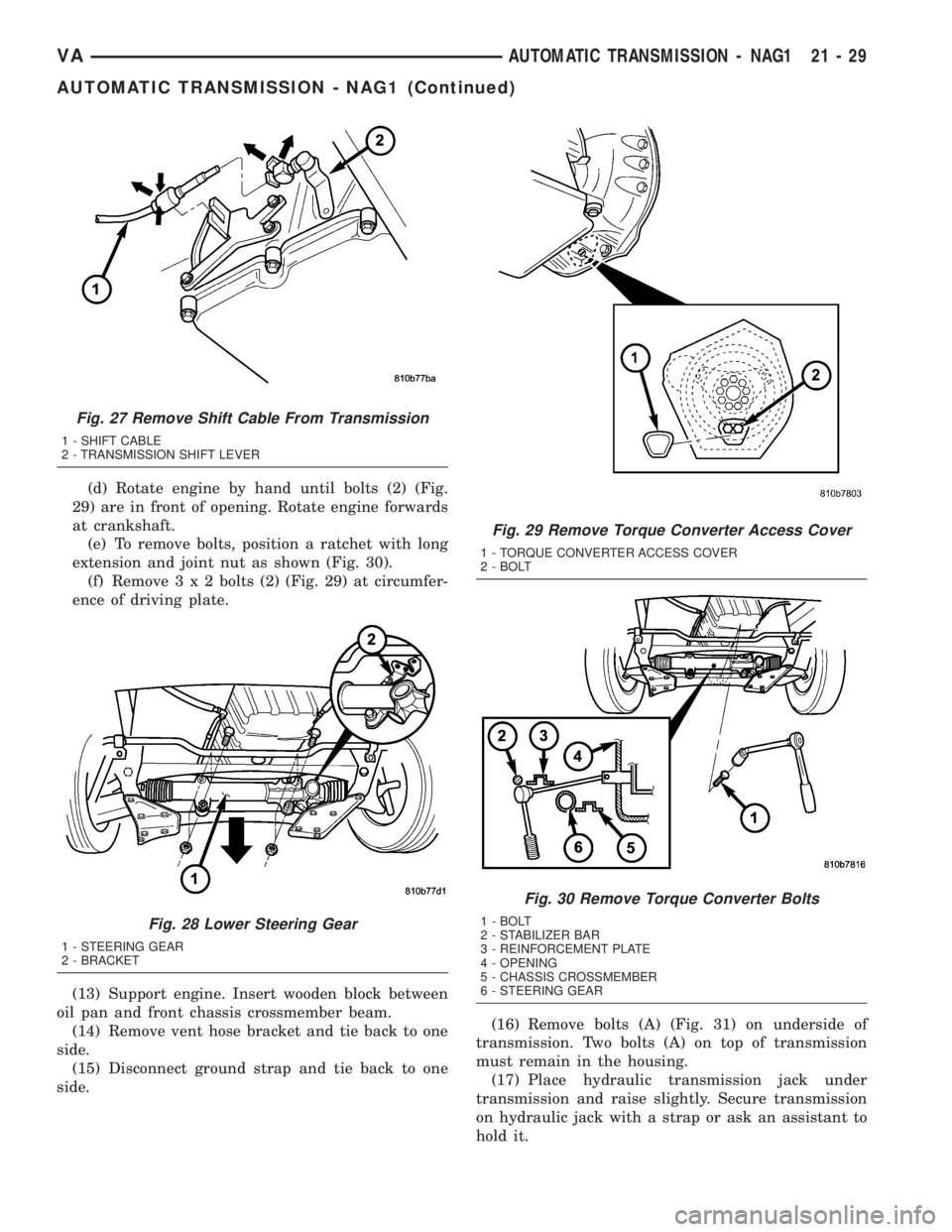
(d) Rotate engine by hand until bolts (2) (Fig.
29) are in front of opening. Rotate engine forwards
at crankshaft.
(e) To remove bolts, position a ratchet with long
extension and joint nut as shown (Fig. 30).
(f) Remove3x2bolts (2) (Fig. 29) at circumfer-
ence of driving plate.
(13) Support engine. Insert wooden block between
oil pan and front chassis crossmember beam.
(14) Remove vent hose bracket and tie back to one
side.
(15) Disconnect ground strap and tie back to one
side.(16) Remove bolts (A) (Fig. 31) on underside of
transmission. Two bolts (A) on top of transmission
must remain in the housing.
(17) Place hydraulic transmission jack under
transmission and raise slightly. Secure transmission
on hydraulic jack with a strap or ask an assistant to
hold it.
Fig. 27 Remove Shift Cable From Transmission
1 - SHIFT CABLE
2 - TRANSMISSION SHIFT LEVER
Fig. 28 Lower Steering Gear
1 - STEERING GEAR
2 - BRACKET
Fig. 29 Remove Torque Converter Access Cover
1 - TORQUE CONVERTER ACCESS COVER
2 - BOLT
Fig. 30 Remove Torque Converter Bolts
1 - BOLT
2 - STABILIZER BAR
3 - REINFORCEMENT PLATE
4 - OPENING
5 - CHASSIS CROSSMEMBER
6 - STEERING GEAR
VAAUTOMATIC TRANSMISSION - NAG1 21 - 29
AUTOMATIC TRANSMISSION - NAG1 (Continued)
Page 1212 of 1232
BACKLITE - BULKHEAD TRIM PANEL -
INSTALLATION.......................23-81
BACKLITE - BULKHEAD TRIM PANEL -
REMOVAL..........................23-81
BACKUP LAMP BULB - INSTALLATION.....8L-6
BACKUP LAMP BULB - REMOVAL........8L-5
BALANCE - STANDARD PROCEDURE,
TIRE AND WHEEL.....................22-3
BALL JOINT - INSTALLATION, LOWER......2-6
BALL JOINT - REMOVAL, LOWER..........2-6
BAR - DESCRIPTION, STABILIZER.........2-9
BAR - INSTALLATION, STABILIZER.....2-15,2-9
BAR - OPERATION, STABILIZER...........2-9
BAR - REMOVAL, STABILIZER........2-15,2-9
BASE BRAKE, SPECIFICATIONS............5-6
BASE BRAKE SYSTEM - DIAGNOSIS AND
TESTING.............................5-2
BASECOAT/CLEARCOAT FINISH -
DESCRIPTION.......................23-74
BATTERY - DESCRIPTION...............8F-6
BATTERY - DIAGNOSIS AND TESTING.....8F-7
BATTERY - OPERATION.................8F-7
BATTERY CABLES - DESCRIPTION.......8F-14
BATTERY CABLES - DIAGNOSIS AND
TESTING...........................8F-14
BATTERY CABLES - INSTALLATION.......8F-16
BATTERY CABLES - OPERATION.........8F-14
BATTERY CABLES - REMOVAL..........8F-16
BATTERY CHARGING - STANDARD
PROCEDURE.........................8F-8
BATTERY ELECTROLYTE LEVEL -
STANDARD PROCEDURE, CHECKING.....8F-12
BATTERY HOLDDOWN - DESCRIPTION....8F-14
BATTERY HOLDDOWN - INSTALLATION . . . 8F-14
BATTERY HOLDDOWN - REMOVAL.......8F-14
BATTERY INSTALLATION, INSTALLATION
- AUXILIARY........................8F-13
BATTERY INSTALLATION, INSTALLATION
- UNDER HOOD......................8F-13
BATTERY REMOVAL, REMOVAL -
AUXILIARY..........................8F-13
BATTERY REMOVAL, REMOVAL - UNDER
HOOD..............................8F-12
BATTERY SYSTEM - CLEANING...........8F-5
BATTERY SYSTEM - DESCRIPTION........8F-1
BATTERY SYSTEM - DIAGNOSIS AND
TESTING............................8F-2
BATTERY SYSTEM - INSPECTION.........8F-6
BATTERY SYSTEM - OPERATION.........8F-2
BATTERY SYSTEM SPECIAL TOOLS,
SPECIAL TOOLS......................8F-6
BATTERY TESTER - STANDARD
PROCEDURE, USING MICRO 420........8F-11
BATTERY TRAY - DESCRIPTION.........8F-16
BATTERY TRAY - INSTALLATION.........8F-16
BATTERY TRAY - OPERATION...........8F-16
BATTERY TRAY - REMOVAL............8F-16
BEAM HEADLAMP BULB -
INSTALLATION, HIGH.................8L-17
BEAM HEADLAMP BULB -
INSTALLATION, LOW..................8L-19
BEAM HEADLAMP BULB - REMOVAL,
HIGH..............................8L-17
BEAM HEADLAMP BULB - REMOVAL,
LOW ..............................8L-18
BEAM INDICATOR - DESCRIPTION, HIGH . . 8J-17
BEAM INDICATOR - OPERATION, HIGH....8J-17
BEARING - INSTALLATION, CENTER........3-9
BEARING - INSTALLATION, HUB...........2-5
BEARING - INSTALLATION, OUTPUT
SHAFT............................21-122
BEARING - REMOVAL, CENTER...........3-8
BEARING - REMOVAL, HUB..............2-4
BEARING - REMOVAL, OUTPUT SHAFT . . . 21-122
BEARINGS/SEALS - INSTALLATION, AXLE . . 3-17
BEARINGS/SEALS - INSTALLATION, AXLE
HUB................................3-20
BEARINGS/SEALS - REMOVAL, AXLE......3-17
BEARINGS/SEALS - REMOVAL, AXLE
HUB
................................3-20
BELT - DIAGNOSIS AND TESTING,
ACCESSORY DRIVE
.....................7-5
BELT & RETRACTOR - INSTALLATION,
FRONT SEAT
........................8O-21
BELT & RETRACTOR - INSTALLATION,
REAR SEAT
.........................8O-29
BELT & RETRACTOR - REMOVAL, FRONT
SEAT
..............................8O-19BELT & RETRACTOR - REMOVAL, REAR
SEAT ..............................8O-27
BELT BUCKLE - INSTALLATION, FRONT
SEAT ..............................8O-23
BELT BUCKLE - REMOVAL, FRONT SEAT . . 8O-22
BELT SWITCH - DESCRIPTION, SEAT.....8O-31
BELT SWITCH - OPERATION, SEAT.......8O-31
BELT TENSIONER - DESCRIPTION, SEAT . . 8O-31
BELT TENSIONER - OPERATION, SEAT....8O-32
BELT TENSIONERS - DESCRIPTION........7-5
BELT TENSIONERS - OPERATION..........7-5
BELT TURNING LOOP ADJUSTER -
INSTALLATION, SEAT.................8O-34
BELT TURNING LOOP ADJUSTER -
REMOVAL, SEAT.....................8O-33
BELT WEATHERSTRIP - INSTALLATION,
FRONT DOOR INNER..................23-87
BELT WEATHERSTRIP - INSTALLATION,
FRONT DOOR OUTER.................23-87
BELT WEATHERSTRIP - REMOVAL,
FRONT DOOR INNER..................23-87
BELT WEATHERSTRIP - REMOVAL,
FRONT DOOR OUTER.................23-87
BELTS - INSTALLATION, DRIVE............7-8
BELTS - REMOVAL, DRIVE...............7-8
BEZEL - INSTALLATION, ACCESSORY
SWITCH............................23-54
BEZEL - INSTALLATION, CLUSTER.......23-54
BEZEL - INSTALLATION, INSTRUMENT
PANEL CENTER......................23-55
BEZEL - REMOVAL, ACCESSORY SWITCH . 23-54
BEZEL - REMOVAL, CLUSTER...........23-53
BEZEL - REMOVAL, INSTRUMENT PANEL
CENTER............................23-55
BLADE - DESCRIPTION, WIPER.........8R-15
BLADE - INSTALLATION, WIPER.........8R-16
BLADE - OPERATION, WIPER...........8R-15
BLADE - REMOVAL, WIPER............8R-16
BLEED PROCEDURE, STANDARD
PROCEDURE - POWER STEERING
PUMP FILL.........................19-14
BLEEDING - STANDARD PROCEDURE,
MANUAL.............................5-4
BLEEDING - STANDARD PROCEDURE,
MASTER CYLINDER...................5-17
BLEEDING - STANDARD PROCEDURE,
PRESSURE...........................5-5
BLOCK - DESCRIPTION, BLOWER
MOTOR RESISTOR...................24-16
BLOCK - DIAGNOSIS AND TESTING,
BLOWER MOTOR RESISTOR............24-16
BLOCK - INSTALLATION, BLOWER
MOTOR RESISTOR...................24-17
BLOCK - OPERATION, BLOWER MOTOR
RESISTOR..........................24-16
BLOCK - REMOVAL, BLOWER MOTOR
RESISTOR..........................24-16
BLOCK #1 - DESCRIPTION, FUSE......8W-97-2
BLOCK #1 - INSTALLATION, FUSE.....8W-97-3
BLOCK #1 - OPERATION, FUSE.......8W-97-2
BLOCK #1 - REMOVAL, FUSE.........8W-97-3
BLOCK #2 - DESCRIPTION, FUSE......8W-97-3
BLOCK #2 - OPERATION, FUSE.......8W-97-3
BLOCK HEATER - INSTALLATION,
ENGINE.............................7-14
BLOCK HEATER - REMOVAL, ENGINE......7-14
BLOCK JOURNALS - STANDARD
PROCEDURE, MEASURE CRANKSHAFT
....9-35
BLOWER MOTOR - INSTALLATION
. . 24-33,24-40
BLOWER MOTOR - REMOVAL
......24-32,24-39
BLOWER MOTOR RELAY - DESCRIPTION
. . 24-23
BLOWER MOTOR RELAY - DIAGNOSIS
AND TESTING
.......................24-24
BLOWER MOTOR RELAY -
INSTALLATION
.......................24-24
BLOWER MOTOR RELAY - OPERATION
. . . 24-23
BLOWER MOTOR RELAY - REMOVAL
.....24-24
BLOWER MOTOR RESISTOR BLOCK -
DESCRIPTION
.......................24-16
BLOWER MOTOR RESISTOR BLOCK -
DIAGNOSIS AND TESTING
.............24-16
BLOWER MOTOR RESISTOR BLOCK -
INSTALLATION
.......................24-17
BLOWER MOTOR RESISTOR BLOCK -
OPERATION
.........................24-16
BLOWER MOTOR RESISTOR BLOCK -
REMOVAL
..........................24-16BLOWER MOTOR SWITCH -
DESCRIPTION..................24-17,24-22
BLOWER MOTOR SWITCH - DIAGNOSIS
AND TESTING..................24-17,24-23
BLOWER MOTOR SWITCH -
INSTALLATION.......................24-23
BLOWER MOTOR SWITCH - OPERATION . . 24-17,
24-22
BLOWER MOTOR SWITCH - REMOVAL . . . 24-17,
24-23
BODY & CABLE - INSTALLATION,
ANTENNA...........................8A-1
BODY & CABLE - REMOVAL, ANTENNA....8A-1
BODY PANEL REPAIR - STANDARD
PROCEDURE, PLASTIC.................23-3
BOLT INSPECTION - STANDARD
PROCEDURE, CYLINDER HEAD...........9-21
BOOST PRESSURE SENSOR -
DESCRIPTION.......................14-17
BOOST PRESSURE SENSOR -
DIAGNOSIS AND TESTING.............14-18
BOOST PRESSURE SENSOR -
INSTALLATION.......................14-18
BOOST PRESSURE SENSOR -
OPERATION.........................14-18
BOOST PRESSURE SENSOR - REMOVAL . . 14-18
BOOSTER - DESCRIPTION, POWER
BRAKE..............................5-19
BOOSTER - DIAGNOSIS AND TESTING,
MASTER CYLINDER/POWER.............5-16
BOOSTER - INSTALLATION, POWER
BRAKE..............................5-19
BOOSTER - OPERATION, POWER BRAKE....5-19
BOOSTER - REMOVAL, POWER BRAKE....5-19
BORES - STANDARD PROCEDURE,
MEASURING CYLINDER................9-34
BOX - INSTALLATION, GLOVE...........23-56
BOX - REMOVAL, GLOVE..............23-56
B-PILLAR TRIM - INSTALLATION........23-69
B-PILLAR TRIM - REMOVAL............23-68
BRACKET - INSTALLATION, LICENSE
PLATE .............................23-47
BRACKET - INSTALLATION, PASSENGER
AIRBAG............................8O-27
BRACKET - INSTALLATION, REAR VIEW
MIRROR SUPPORT...................23-72
BRACKET - REMOVAL, LICENSE PLATE . . . 23-47
BRACKET - REMOVAL, PASSENGER
AIRBAG............................8O-27
BRAKE - CLEANING, REAR DRUM IN
HAT ................................5-27
BRAKE - DESCRIPTION, CONTROLLER
ANTILOCK...........................8E-3
BRAKE - INSTALLATION, CONTROLLER
ANTILOCK...........................8E-3
BRAKE - REMOVAL, CONTROLLER
ANTILOCK...........................8E-3
BRAKE BOOSTER - DESCRIPTION,
POWER.............................5-19
BRAKE BOOSTER - INSTALLATION,
POWER.............................5-19
BRAKE BOOSTER - OPERATION, POWER . . . 5-19
BRAKE BOOSTER - REMOVAL, POWER....5-19
BRAKE CABLES - ADJUSTMENT,
PARKING............................5-25
BRAKE FLUID - DESCRIPTION............0-3
BRAKE FLUID CONTAMINATION -
DIAGNOSIS AND TESTING..............5-14
BRAKE FLUID LEVEL - STANDARD
PROCEDURE.........................5-14
BRAKE FLUID, SPECIFICATIONS..........5-14
BRAKE INDICATOR - DESCRIPTION,
BRAKE/PARK........................8J-11
BRAKE INDICATOR - OPERATION,
BRAKE/PARK........................8J-12
BRAKE LAMP SWITCH - INSTALLATION....8L-6
BRAKE LAMP SWITCH - REMOVAL.......8L-6
BRAKE, SPECIAL TOOLS - PARK.........5-23
BRAKE, SPECIFICATIONS - BASE..........5-6
BRAKE SWITCH - INSTALLATION, PARK . . . 8L-20
BRAKE SWITCH - REMOVAL, PARK
......8L-20
BRAKE SYSTEM - DIAGNOSIS AND
TESTING, BASE
........................5-2
BRAKE WEAR INDICATOR -
DESCRIPTION
.......................8J-12
BRAKE WEAR INDICATOR - OPERATION
. . . 8J-12
BRAKE/PARK BRAKE INDICATOR -
DESCRIPTION
.......................8J-11
2 INDEXVA
Description Group-Page Description Group-Page Description Group-Page
Page 1213 of 1232
BRAKE/PARK BRAKE INDICATOR -
OPERATION.........................8J-12
BRAKE/PARK LAMP BULB -
INSTALLATION........................8L-7
BRAKE/PARK LAMP BULB - REMOVAL.....8L-7
BRAKES, SPECIAL TOOLS................5-7
BREAKER - DESCRIPTION, CIRCUIT....8W-97-2
BREAKER - DIAGNOSIS AND TESTING,
CIRCUIT.........................8W-97-2
BREAKER - OPERATION, CIRCUIT.....8W-97-2
BREAK-IN - STANDARD PROCEDURE,
COMPRESSOR CLUTCH................24-9
BUCKLE - INSTALLATION, FRONT SEAT
BELT ..............................8O-23
BUCKLE - REMOVAL, FRONT SEAT BELT . . 8O-22
BULB - INSTALLATION, BACKUP LAMP....8L-6
BULB - INSTALLATION, BRAKE/PARK
LAMP...............................8L-7
BULB - INSTALLATION, CARGO/DOME
LAMP..............................8L-27
BULB - INSTALLATION, CENTER HIGH
MOUNTED STOP LAMP.................8L-7
BULB - INSTALLATION, CLEARANCE
LAMP...............................8L-8
BULB - INSTALLATION, DOME
LAMP/INTRUSION SENSOR.............8L-30
BULB - INSTALLATION, DOME/READING
LAMP..............................8L-29
BULB - INSTALLATION, ENTRY/EXIT
LAMP..............................8L-32
BULB - INSTALLATION, FOG LAMP.......8L-10
BULB - INSTALLATION, FRONT POSITION
LAMP..............................8L-14
BULB - INSTALLATION, FRONT
TURN/PARK/SIDE MARKER LAMP.......8L-15
BULB - INSTALLATION, HIGH BEAM
HEADLAMP.........................8L-17
BULB - INSTALLATION, LICENSE PLATE
LAMP..............................8L-18
BULB - INSTALLATION, LOW BEAM
HEADLAMP.........................8L-19
BULB - INSTALLATION, REAR SIDE
MARKER LAMP......................8L-21
BULB - INSTALLATION, REAR TURN
LAMP..............................8L-22
BULB - INSTALLATION, REPEATER LAMP . . 8L-22
BULB - REMOVAL, BACKUP LAMP........8L-5
BULB - REMOVAL, BRAKE/PARK LAMP....8L-7
BULB - REMOVAL, CARGO/DOME LAMP . . 8L-27
BULB - REMOVAL, CENTER HIGH
MOUNTED STOP LAMP.................8L-7
BULB - REMOVAL, CLEARANCE LAMP.....8L-8
BULB - REMOVAL, DOME LAMP/
INTRUSION SENSOR..................8L-30
BULB - REMOVAL, DOME/READING
LAMP..............................8L-29
BULB - REMOVAL, ENTRY/EXIT LAMP....8L-31
BULB - REMOVAL, FOG LAMP..........8L-10
BULB - REMOVAL, FRONT POSITION
LAMP..............................8L-14
BULB - REMOVAL, FRONT TURN/PARK/
SIDE MARKER LAMP.................8L-14
BULB - REMOVAL, HIGH BEAM
HEADLAMP.........................8L-17
BULB - REMOVAL, LICENSE PLATE
LAMP..............................8L-17
BULB - REMOVAL, LOW BEAM
HEADLAMP.........................8L-18
BULB - REMOVAL, REAR SIDE MARKER
LAMP..............................8L-21
BULB - REMOVAL, REAR TURN LAMP....8L-21
BULB - REMOVAL, REPEATER LAMP.....8L-22
BULKHEAD - INSTALLATION............8L-29
BULKHEAD - REMOVAL................8L-28
BULKHEAD TRIM PANEL -
INSTALLATION.......................23-69
BULKHEAD TRIM PANEL -
INSTALLATION, BACKLITE..............23-81
BULKHEAD TRIM PANEL - REMOVAL.....23-69
BULKHEAD TRIM PANEL - REMOVAL,
BACKLITE..........................23-81
BUMPER - STEP - INSTALLATION, REAR
. . . 13-3
BUMPER - STEP - REMOVAL, REAR
.......13-3
BUMPER - STEPS - INSTALLATION,
FRONT
..............................13-2
BUMPER - STEPS - REMOVAL, FRONT
.....13-2
BURNT FLUID - DIAGNOSIS AND
TESTING, CAUSES OF
................21-102BUSHINGS - INSTALLATION..............2-3
BUSHINGS - REMOVAL..................2-3
BUZZ, SQUEAK & RATTLE - STANDARD
PROCEDURE........................23-10
CABIN HEATER - DESCRIPTION.........24-72
CABIN HEATER - OPERATION...........24-72
CABLE - DESCRIPTION.................8P-3
CABLE - DIAGNOSIS AND TESTING,
GEARSHIFT........................21-109
CABLE - INSTALLATION, ANTENNA BODY . . 8A-1
CABLE - INSTALLATION, GEARSHIFT....21-109
CABLE - INSTALLATION, INSTRUMENT
PANEL ANTENNA......................8A-2
CABLE - INSTALLATION, LATCH RELEASE . 23-51
CABLE - INSTALLATION, PARK LOCK....21-126
CABLE - REMOVAL, ANTENNA BODY......8A-1
CABLE - REMOVAL, GEARSHIFT........21-109
CABLE - REMOVAL, INSTRUMENT PANEL
ANTENNA...........................8A-1
CABLE - REMOVAL, LATCH RELEASE.....23-51
CABLE - REMOVAL, PARK LOCK........21-125
CABLE TENSIONER - INSTALLATION......5-23
CABLE TENSIONER - REMOVAL..........5-23
CABLES - ADJUSTMENT, PARKING
BRAKE..............................5-25
CABLES - DESCRIPTION, BATTERY.......8F-14
CABLES - DIAGNOSIS AND TESTING,
BATTERY...........................8F-14
CABLES - INSTALLATION, BATTERY......8F-16
CABLES - INSTALLATION, MODE DOOR . . . 24-19
CABLES - OPERATION, BATTERY........8F-14
CABLES - REMOVAL, BATTERY..........8F-16
CABLES - REMOVAL, MODE DOOR.......24-19
CAMSHAFT POSITION - STANDARD
PROCEDURE, CHECKING................9-27
CAMSHAFT POSITION SENSOR -
DESCRIPTION.......................14-19
CAMSHAFT POSITION SENSOR -
INSTALLATION.......................14-19
CAMSHAFT POSITION SENSOR -
OPERATION.........................14-19
CAMSHAFT POSITION SENSOR -
REMOVAL..........................14-19
CAMSHAFT(S) - INSTALLATION..........9-29
CAMSHAFT(S) - REMOVAL..............9-28
CAP - DESCRIPTION, RADIATOR
PRESSURE..........................7-18
CAP - DIAGNOSIS AND TESTING,
RADIATOR PRESSURE.................7-19
CAP - OPERATION, RADIATOR
PRESSURE..........................7-18
CAPACITIES - SPECIFICATIONS, FLUID......0-4
CAPACITY, SPECIFICATIONS - CHARGE . . . 24-49
CARGO/DOME LAMP BULB -
INSTALLATION.......................8L-27
CARGO/DOME LAMP BULB - REMOVAL . . . 8L-27
CARGO/DOME LAMP UNIT -
INSTALLATION.......................8L-28
CARGO/DOME LAMP UNIT - REMOVAL . . . 8L-28
CARPETS AND FLOOR MATS -
INSTALLATION.......................23-70
CARPETS AND FLOOR MATS - REMOVAL . 23-69
CARRIER - INSTALLATION, SPARE TIRE . . . 22-10
CARRIER - REMOVAL, SPARE TIRE......22-10
CATALYTIC CONVERTER - INSTALLATION . . . 11-3
CATALYTIC CONVERTER - REMOVAL......11-3
CAUSES OF BURNT FLUID - DIAGNOSIS
AND TESTING
......................21-102
CAUTION - CAUTION
..................24-45
CAUTION - REFRIGERANT HOSES/LINES/
TUBES PRECAUTIONS
.................24-45
CAUTION, CAUTION
...................24-45
CAUTION, INTERIOR
..................23-67
CENTER - DESCRIPTION, POWER
DISTRIBUTION
....................8W-97-3
CENTER - OPERATION, POWER
DISTRIBUTION
....................8W-97-3
CENTER BEARING - INSTALLATION
........3-9
CENTER BEARING - REMOVAL
............3-8
CENTER BEZEL - INSTALLATION,
INSTRUMENT PANEL
..................23-55
CENTER BEZEL - REMOVAL,
INSTRUMENT PANEL
..................23-55
CENTER HIGH MOUNTED STOP LAMP
BULB - INSTALLATION
.................8L-7
CENTER HIGH MOUNTED STOP LAMP
BULB - REMOVAL
.....................8L-7CENTER HIGH MOUNTED STOP LAMP
UN - INSTALLATION...................8L-8
CENTER HIGH MOUNTED STOP LAMP
UN - REMOVAL.......................8L-8
CENTER ROLLER ARM - INSTALLATION . . . 23-38
CENTER ROLLER ARM - REMOVAL......23-37
CENTER TRACK - INSTALLATION........23-39
CENTER TRACK - REMOVAL............23-38
CENTERING - STANDARD PROCEDURE,
CLOCKSPRING......................8O-13
CENTRAL TIMER MODULE -
DESCRIPTION........................8E-1
CENTRAL TIMER MODULE - DIAGNOSIS
AND TESTING........................8E-2
CENTRAL TIMER MODULE -
INSTALLATION........................8E-2
CENTRAL TIMER MODULE - OPERATION . . . 8E-2
CENTRAL TIMER MODULE - REMOVAL....8E-2
CHAIN - INSTALLATION, OIL PUMP.......9-54
CHAIN - INSTALLATION, TIMING.........9-67
CHAIN - REMOVAL, OIL PUMP...........9-53
CHAIN - REMOVAL, TIMING.............9-63
CHAIN COVER - INSTALLATION, TIMING . . . 9-60
CHAIN COVER - REMOVAL, TIMING.......9-59
CHAIN TENSIONER - INSTALLATION,
TIMING.............................9-71
CHAIN TENSIONER - REMOVAL, TIMING . . . 9-70
CHAIN TENSIONING RAIL -
INSTALLATION, TIMING.................9-66
CHAIN TENSIONING RAIL - REMOVAL,
TIMING.............................9-63
CHARGE - STANDARD PROCEDURE,
REFRIGERANT SYSTEM...............24-48
CHARGE AIR COOLER AND PLUMBING -
CLEANING...........................11-5
CHARGE AIR COOLER AND PLUMBING -
DESCRIPTION........................11-4
CHARGE AIR COOLER AND PLUMBING -
INSPECTION.........................11-5
CHARGE AIR COOLER AND PLUMBING -
INSTALLATION........................11-5
CHARGE AIR COOLER AND PLUMBING -
OPERATION..........................11-4
CHARGE AIR COOLER AND PLUMBING -
REMOVAL...........................11-5
CHARGE AIR COOLER SYSTEM - LEAKS
- DIAGNOSIS AND TESTING.............11-4
CHARGE CAPACITY, SPECIFICATIONS.....24-49
CHARGING - STANDARD PROCEDURE,
BATTERY............................8F-8
CHARGING INDICATOR - DESCRIPTION . . . 8J-13
CHARGING INDICATOR - OPERATION.....8J-13
CHART - SPECIFICATIONS, TORQUE....5-29,5-5
CHART - SPECIFICATIONS, TORQUE.....19-10,
19-14,19-5,19-9
CHART - SPECIFICATIONS, TORQUE....2-12,2-2
CHART, SPECIFICATIONS - TORQUE.......5-22
CHART, SPECIFICATIONS - TORQUE.......22-5
CHECK - INSTALLATION..........23-13,23-24
CHECK - REMOVAL..............23-13,23-24
CHECK OIL LEVEL - STANDARD
PROCEDURE.......................21-102
CHECK VALVE - DESCRIPTION...........8R-7
CHECK VALVE - INSTALLATION..........8R-7
CHECK VALVE - OPERATION.............8R-7
CHECK VALVE - REMOVAL..............8R-7
CHECKING AND REPAIRING
CONNECTING RODS - STANDARD
PROCEDURE.........................9-40
CHECKING BATTERY ELECTROLYTE
LEVEL - STANDARD PROCEDURE........8F-12
CHECKING CAMSHAFT POSITION -
STANDARD PROCEDURE................9-27
CHECKS - DIAGNOSIS AND TESTING,
PRELIMINARY.........................7-1
CHIME WARNING SYSTEM - DIAGNOSIS
AND TESTING........................8B-2
CHIME/BUZZER - DESCRIPTION..........8B-1
CHIME/BUZZER - OPERATION............8B-1
CIGAR LIGHTER OUTLET -
DESCRIPTION.....................8W-97-1
CIGAR LIGHTER OUTLET - DIAGNOSIS
AND TESTING
.....................8W-97-2
CIGAR LIGHTER OUTLET - OPERATION
. 8W-97-2
CIGAR LIGHTER OUTLET - REMOVAL
. . 8W-97-2
CIRCUIT BREAKER - DESCRIPTION
....8W-97-2
CIRCUIT BREAKER - DIAGNOSIS AND
TESTING
.........................8W-97-2
VAINDEX 3
Description Group-Page Description Group-Page Description Group-Page
Page 1218 of 1232
HAT BRAKE - CLEANING, REAR DRUM
IN .................................5-27
HCU (HYDRAULIC CONTROL UNIT) -
DESCRIPTION........................5-31
HCU (HYDRAULIC CONTROL UNIT) -
INSTALLATION........................5-32
HCU (HYDRAULIC CONTROL UNIT) -
REMOVAL...........................5-31
HEAD - INSTALLATION, CYLINDER........9-25
HEAD - REMOVAL, CYLINDER...........9-22
HEAD BOLT INSPECTION - STANDARD
PROCEDURE, CYLINDER................9-21
HEAD COVER(S) - INSTALLATION,
CYLINDER...........................9-30
HEAD COVER(S) - REMOVAL, CYLINDER . . . 9-30
HEAD FRONT COVER - INSTALLATION,
CYLINDER...........................9-26
HEAD FRONT COVER - REMOVAL,
CYLINDER...........................9-23
HEAD GUIDE RAIL - INSTALLATION,
CYLINDER...........................9-26
HEAD GUIDE RAIL - REMOVAL,
CYLINDER...........................9-24
HEAD SURFACE - STANDARD
PROCEDURE, MEASURE CYLINDER.......9-21
HEADLAMP BULB - INSTALLATION, HIGH
BEAM..............................8L-17
HEADLAMP BULB - INSTALLATION, LOW
BEAM..............................8L-19
HEADLAMP BULB - REMOVAL, HIGH
BEAM..............................8L-17
HEADLAMP BULB - REMOVAL, LOW
BEAM...............................8L-18
HEADLAMP LEVELING MOTOR -
INSTALLATION.......................8L-16
HEADLAMP LEVELING MOTOR -
REMOVAL..........................8L-15
HEADLAMP LEVELING SWITCH -
INSTALLATION.......................8L-17
HEADLAMP LEVELING SWITCH -
REMOVAL..........................8L-16
HEADLINER - INSTALLATION...........23-71
HEADLINER - REMOVAL...............23-70
HEADREST - INSTALLATION............23-76
HEADREST - REMOVAL................23-76
HEATED SEAT ELEMENT - DESCRIPTION . . . 8G-3
HEATED SEAT ELEMENT - DIAGNOSIS
AND TESTING........................8G-3
HEATED SEAT ELEMENT - OPERATION.....8G-3
HEATED SEAT RELAY - DESCRIPTION.....8G-4
HEATED SEAT RELAY - DIAGNOSIS AND
TESTING............................8G-4
HEATED SEAT RELAY - INSTALLATION.....8G-4
HEATED SEAT RELAY - OPERATION.......8G-4
HEATED SEAT RELAY - REMOVAL........8G-4
HEATED SEAT SENSOR - DESCRIPTION....8G-4
HEATED SEAT SENSOR - DIAGNOSIS
AND TESTING........................8G-4
HEATED SEAT SWITCH - DESCRIPTION,
DRIVER.............................8G-2
HEATED SEAT SWITCH - DESCRIPTION,
PASSENGER.........................8G-5
HEATED SEAT SWITCH - DIAGNOSIS
AND TESTING, DRIVER.................8G-2
HEATED SEAT SWITCH - DIAGNOSIS
AND TESTING, PASSENGER.............8G-5
HEATED SEAT SWITCH - INSTALLATION,
DRIVER.............................8G-3
HEATED SEAT SWITCH - INSTALLATION,
PASSENGER.........................8G-5
HEATED SEAT SWITCH - OPERATION,
DRIVER.............................8G-2
HEATED SEAT SWITCH - OPERATION,
PASSENGER.........................8G-5
HEATED SEAT SWITCH - REMOVAL,
DRIVER.............................8G-3
HEATED SEAT SWITCH - REMOVAL,
PASSENGER.........................8G-5
HEATED SEATS - DESCRIPTION..........8G-1
HEATED SEATS - DIAGNOSIS AND
TESTING............................8G-2
HEATED SEATS - OPERATION
............8G-2
HEATER - DCHA - DIAGNOSIS AND
TESTING, DIESEL SUPPLEMENTAL
.......24-72
HEATER - DESCRIPTION, CABIN
.........24-72
HEATER - INSTALLATION, ENGINE
BLOCK
..............................7-14
HEATER - OPERATION, CABIN
...........24-72HEATER - REMOVAL, ENGINE BLOCK......7-14
HEATER AND AIR CONDITIONER -
DESCRIPTION........................24-1
HEATER AND AIR CONDITIONER -
OPERATION..........................24-2
HEATER CONTROL - DESCRIPTION, A/C . . . 24-12
HEATER CONTROL - INSTALLATION, A/C . . 24-13
HEATER CONTROL - OPERATION, A/C....24-12
HEATER CONTROL - REMOVAL, A/C......24-12
HEATER CORE - DESCRIPTION..........24-57
HEATER CORE - INSTALLATION.........24-58
HEATER CORE - OPERATION............24-57
HEATER CORE - REMOVAL.............24-58
HEATER PERFORMANCE - DIAGNOSIS
AND TESTING........................24-4
HI PRESSURE FUEL SHUTOFF SOL -
DESCRIPTION.......................14-16
HI PRESSURE FUEL SHUTOFF SOL -
OPERATION.........................14-16
HIGH BEAM HEADLAMP BULB -
INSTALLATION.......................8L-17
HIGH BEAM HEADLAMP BULB -
REMOVAL..........................8L-17
HIGH BEAM INDICATOR - DESCRIPTION . . 8J-17
HIGH BEAM INDICATOR - OPERATION....8J-17
HIGH FUEL SYSTEM PRESSURE -
WARNING...........................14-1
HIGH MOUNTED STOP LAMP BULB -
INSTALLATION, CENTER................8L-7
HIGH MOUNTED STOP LAMP BULB -
REMOVAL, CENTER....................8L-7
HIGH MOUNTED STOP LAMP UN -
INSTALLATION, CENTER................8L-8
HIGH MOUNTED STOP LAMP UN -
REMOVAL, CENTER....................8L-8
HIGH PRESSURE FUEL LINES -
DIAGNOSIS AND TESTING..............14-1
HIGH PRESSURE LINES - INSTALLATION . . . 14-7
HIGH PRESSURE LINES - REMOVAL......14-6
HIGH PRESSURE PUMP - DESCRIPTION . . . 14-7
HIGH PRESSURE PUMP - INSTALLATION . . 14-10
HIGH PRESSURE PUMP - REMOVAL......14-8
HIGH SPEEDS - DESCRIPTION, TIRE
PRESSURE..........................22-6
HINGE - INSTALLATION......23-17,23-34,23-50
HINGE - REMOVAL.........23-17,23-34,23-50
HITCH - INSTALLATION, TRAILER........13-10
HITCH - REMOVAL, TRAILER............13-9
HOAT COOLANT - DESCRIPTION..........0-2
HOISTING - STANDARD PROCEDURE.......0-5
HOLDDOWN - DESCRIPTION, BATTERY . . . 8F-14
HOLDDOWN - INSTALLATION, BATTERY . . . 8F-14
HOLDDOWN - REMOVAL, BATTERY......8F-14
HOLDER - INSTALLATION, CUP.........23-56
HOLDER - REMOVAL, CUP.............23-55
HOLDING CLUTCH B1 - ASSEMBLY.....21-113
HOLDING CLUTCH B1 - DISASSEMBLY . . 21-112
HOLDING CLUTCH B2 - ASSEMBLY.....21-116
HOLDING CLUTCH B2 - DISASSEMBLY . . 21-115
HOLDING CLUTCHES - DESCRIPTION....21-111
HOLDING CLUTCHES - OPERATION.....21-112
HOLE REPAIR - DESCRIPTION,
THREADED........................Intro.-5
HOOD - INSTALLATION................23-50
HOOD - REMOVAL....................23-50
HOOD BATTERY INSTALLATION,
INSTALLATION - UNDER...............8F-13
HOOD BATTERY REMOVAL, REMOVAL -
UNDER.............................8F-12
HORN - INSTALLATION.................8H-1
HORN - REMOVAL....................8H-1
HORN SWITCH - INSTALLATION
..........8H-1
HORN SWITCH - REMOVAL
.............8H-1
HOSE - INSTALLATION, INLET
..........24-78
HOSE - INSTALLATION, PRESSURE
......19-15
HOSE - REMOVAL, INLET
..............24-78
HOSE - REMOVAL, PRESSURE
..........19-15
HOSE FROM GEAR TO COOLER TUBE -
INSTALLATION, RETURN
...............19-15
HOSE FROM GEAR TO COOLER TUBE -
REMOVAL, RETURN
..................19-15
HOSES/LINES/TUBES PRECAUTIONS,
CAUTION - REFRIGERANT
..............24-45
HOSES/TUBES - DESCRIPTION, WASHER
. . 8R-8
HOSES/TUBES - OPERATION, WASHER
....8R-9
HOUSING - ASSEMBLY, HVAC
...........24-36
HOUSING - DISASSEMBLY, HVAC
........24-36HOUSING - INSTALLATION, AIR
CLEANER............................9-20
HOUSING - INSTALLATION, HVAC........24-36
HOUSING - INSTALLATION, REAR A/C....24-41
HOUSING - REMOVAL, AIR CLEANER......9-20
HOUSING - REMOVAL, HVAC...........24-34
HOUSING - REMOVAL, REAR A/C........24-40
HOW TO USE WIRING DIAGRAMS -
DESCRIPTION.....................8W-01-1
HUB / BEARING - INSTALLATION..........2-5
HUB / BEARING - REMOVAL..............2-4
HUB BEARINGS/SEALS - INSTALLATION,
AXLE...............................3-20
HUB BEARINGS/SEALS - REMOVAL,
AXLE...............................3-20
HUB SEAL - INSTALLATION, TORQUE
CONVERTER.......................21-147
HUB SEAL - REMOVAL, TORQUE
CONVERTER.......................21-147
HVAC HOUSING - ASSEMBLY...........24-36
HVAC HOUSING - DISASSEMBLY........24-36
HVAC HOUSING - INSTALLATION........24-36
HVAC HOUSING - REMOVAL............24-34
IDENTIFICATION - DESCRIPTION,
FASTENER.........................Intro.-2
IDENTIFICATION AND INFORMATION -
DESCRIPTION, SECTION.............8W-01-5
IDENTIFICATION NUMBER -
DESCRIPTION, VEHICLE..............Intro.-1
IGNITION CONTROL - SPECIAL TOOLS......8I-1
IGNITION-OFF DRAW TEST - STANDARD
PROCEDURE........................8F-10
INBOARD - INSTALLATION.............8O-30
INBOARD - REMOVAL.................8O-29
IN-CAR TEMPERATURE SENSOR -
DESCRIPTION.......................24-19
IN-CAR TEMPERATURE SENSOR -
DIAGNOSIS AND TESTING.............24-19
IN-CAR TEMPERATURE SENSOR -
OPERATION.........................24-19
IN-CAR TEMPERATURE SENSOR -
REMOVAL..........................24-19
INCORRECT FLUID LEVEL - DIAGNOSIS
AND TESTING, EFFECTS OF............21-102
INDICATOR - DESCRIPTION, ABS.........8J-9
INDICATOR - DESCRIPTION, AIRBAG.....8J-10
INDICATOR - DESCRIPTION, AMBIENT
TEMPERATURE......................8J-11
INDICATOR - DESCRIPTION, BRAKE
WEAR.............................8J-12
INDICATOR - DESCRIPTION, BRAKE/
PARK BRAKE........................8J-11
INDICATOR - DESCRIPTION, CHARGING . . . 8J-13
INDICATOR - DESCRIPTION, COOLANT
LOW...............................8J-14
INDICATOR - DESCRIPTION, FUEL
FILTER CLOGGED.....................8J-15
INDICATOR - DESCRIPTION, GEAR
SELECTOR..........................8J-17
INDICATOR - DESCRIPTION, HIGH BEAM . . 8J-17
INDICATOR - DESCRIPTION, LOW FUEL . . . 8J-18
INDICATOR - DESCRIPTION, LOW OIL
LEVEL.............................8J-18
INDICATOR - DESCRIPTION,
MAINTENANCE.......................8J-19
INDICATOR - DESCRIPTION, MULTI-
FUNCTION..........................8J-20
INDICATOR - DESCRIPTION, SEATBELT . . . 8J-22
INDICATOR - DESCRIPTION, TRACTION
CONTROL...........................8J-24
INDICATOR - DESCRIPTION, TRACTION
CONTROL MALFUNCTION..............8J-25
INDICATOR - DESCRIPTION, TURN
SIGNAL............................8J-25
INDICATOR - DESCRIPTION, WAIT-TO-
START .............................8J-26
INDICATOR - DESCRIPTION, WASHER
FLUID..............................8J-27
INDICATOR - DESCRIPTION, WATER-IN-
FUEL..............................8J-27
INDICATOR - OPERATION, ABS...........8J-9
INDICATOR - OPERATION, AIRBAG
.......8J-10
INDICATOR - OPERATION, AMBIENT
TEMPERATURE
......................8J-11
INDICATOR - OPERATION, BRAKE WEAR
. . 8J-12
INDICATOR - OPERATION, BRAKE/PARK
BRAKE
.............................8J-12
INDICATOR - OPERATION, CHARGING
....8J-13
8 INDEXVA
Description Group-Page Description Group-Page Description Group-Page