2005 MERCEDES-BENZ SPRINTER wiper fluid
[x] Cancel search: wiper fluidPage 291 of 1232
washer hose fittings cannot be repaired. If these fittings
are faulty or damaged, they must be replaced.
OPERATION
Washer fluid in the washer reservoir is pressurized
and fed by the washer pump/motor through the
washer system plumbing and fittings to the two
washer nozzles. Whenever routing the washer hose
or a wire harness containing a washer hose, it must
be routed away from hot, sharp, or moving parts;
and, sharp bends that might pinch the hose must be
avoided.
WASHER NOZZLE
DESCRIPTION
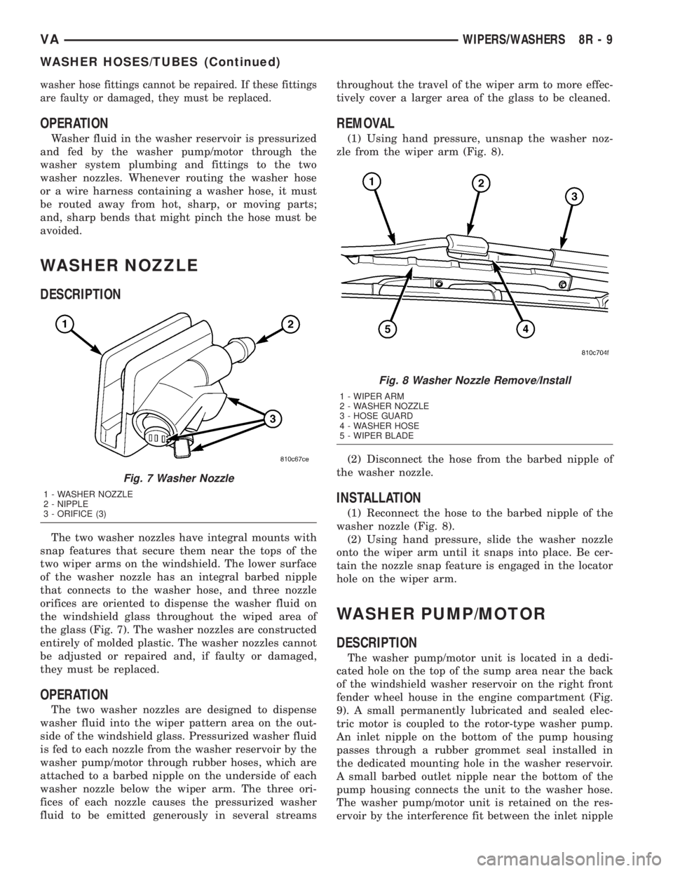
The two washer nozzles have integral mounts with
snap features that secure them near the tops of the
two wiper arms on the windshield. The lower surface
of the washer nozzle has an integral barbed nipple
that connects to the washer hose, and three nozzle
orifices are oriented to dispense the washer fluid on
the windshield glass throughout the wiped area of
the glass (Fig. 7). The washer nozzles are constructed
entirely of molded plastic. The washer nozzles cannot
be adjusted or repaired and, if faulty or damaged,
they must be replaced.
OPERATION
The two washer nozzles are designed to dispense
washer fluid into the wiper pattern area on the out-
side of the windshield glass. Pressurized washer fluid
is fed to each nozzle from the washer reservoir by the
washer pump/motor through rubber hoses, which are
attached to a barbed nipple on the underside of each
washer nozzle below the wiper arm. The three ori-
fices of each nozzle causes the pressurized washer
fluid to be emitted generously in several streamsthroughout the travel of the wiper arm to more effec-
tively cover a larger area of the glass to be cleaned.
REMOVAL
(1) Using hand pressure, unsnap the washer noz-
zle from the wiper arm (Fig. 8).
(2) Disconnect the hose from the barbed nipple of
the washer nozzle.
INSTALLATION
(1) Reconnect the hose to the barbed nipple of the
washer nozzle (Fig. 8).
(2) Using hand pressure, slide the washer nozzle
onto the wiper arm until it snaps into place. Be cer-
tain the nozzle snap feature is engaged in the locator
hole on the wiper arm.
WASHER PUMP/MOTOR
DESCRIPTION
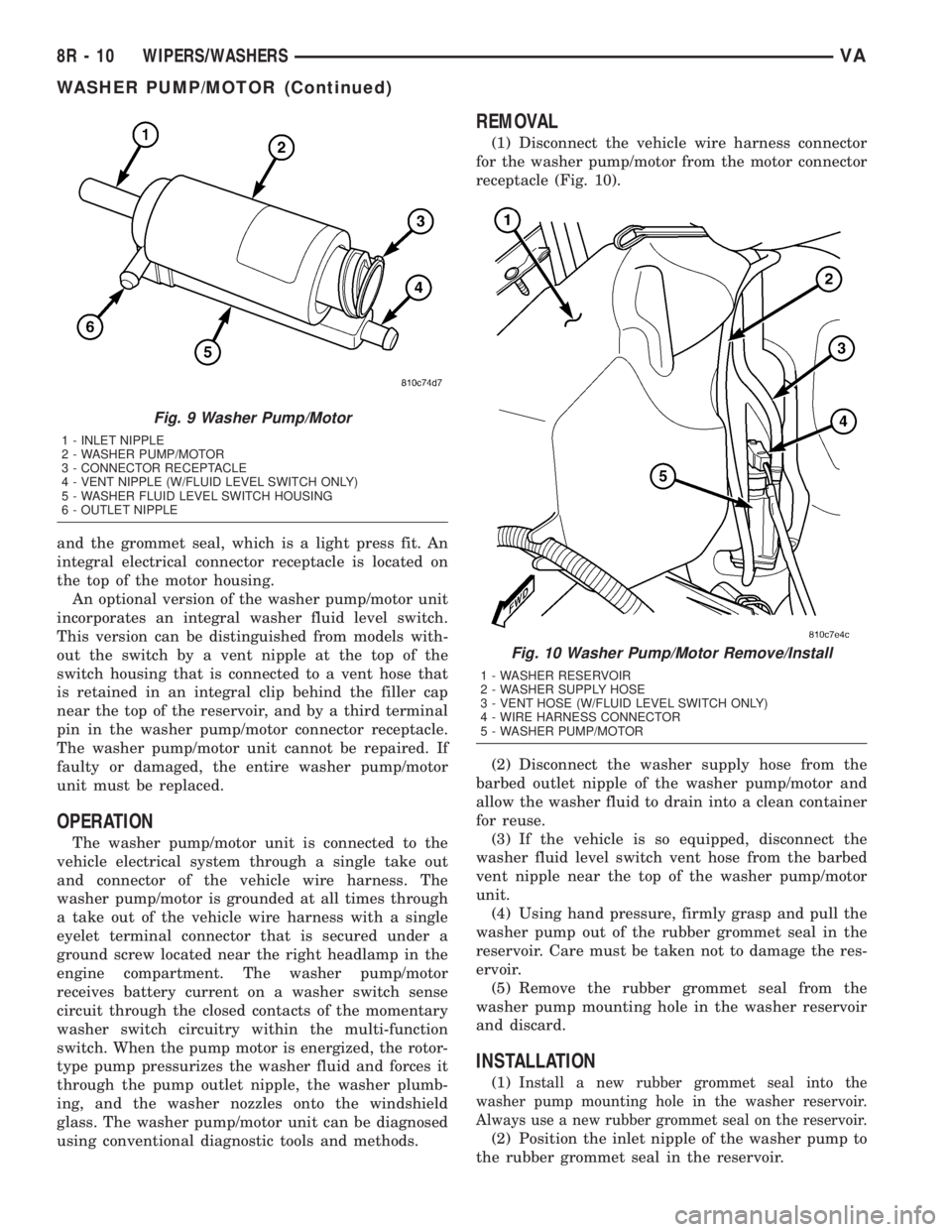
The washer pump/motor unit is located in a dedi-
cated hole on the top of the sump area near the back
of the windshield washer reservoir on the right front
fender wheel house in the engine compartment (Fig.
9). A small permanently lubricated and sealed elec-
tric motor is coupled to the rotor-type washer pump.
An inlet nipple on the bottom of the pump housing
passes through a rubber grommet seal installed in
the dedicated mounting hole in the washer reservoir.
A small barbed outlet nipple near the bottom of the
pump housing connects the unit to the washer hose.
The washer pump/motor unit is retained on the res-
ervoir by the interference fit between the inlet nipple
Fig. 7 Washer Nozzle
1 - WASHER NOZZLE
2 - NIPPLE
3 - ORIFICE (3)
Fig. 8 Washer Nozzle Remove/Install
1 - WIPER ARM
2 - WASHER NOZZLE
3 - HOSE GUARD
4 - WASHER HOSE
5 - WIPER BLADE
VAWIPERS/WASHERS 8R - 9
WASHER HOSES/TUBES (Continued)
Page 292 of 1232
and the grommet seal, which is a light press fit. An
integral electrical connector receptacle is located on
the top of the motor housing.
An optional version of the washer pump/motor unit
incorporates an integral washer fluid level switch.
This version can be distinguished from models with-
out the switch by a vent nipple at the top of the
switch housing that is connected to a vent hose that
is retained in an integral clip behind the filler cap
near the top of the reservoir, and by a third terminal
pin in the washer pump/motor connector receptacle.
The washer pump/motor unit cannot be repaired. If
faulty or damaged, the entire washer pump/motor
unit must be replaced.
OPERATION
The washer pump/motor unit is connected to the
vehicle electrical system through a single take out
and connector of the vehicle wire harness. The
washer pump/motor is grounded at all times through
a take out of the vehicle wire harness with a single
eyelet terminal connector that is secured under a
ground screw located near the right headlamp in the
engine compartment. The washer pump/motor
receives battery current on a washer switch sense
circuit through the closed contacts of the momentary
washer switch circuitry within the multi-function
switch. When the pump motor is energized, the rotor-
type pump pressurizes the washer fluid and forces it
through the pump outlet nipple, the washer plumb-
ing, and the washer nozzles onto the windshield
glass. The washer pump/motor unit can be diagnosed
using conventional diagnostic tools and methods.
REMOVAL
(1) Disconnect the vehicle wire harness connector
for the washer pump/motor from the motor connector
receptacle (Fig. 10).
(2) Disconnect the washer supply hose from the
barbed outlet nipple of the washer pump/motor and
allow the washer fluid to drain into a clean container
for reuse.
(3) If the vehicle is so equipped, disconnect the
washer fluid level switch vent hose from the barbed
vent nipple near the top of the washer pump/motor
unit.
(4) Using hand pressure, firmly grasp and pull the
washer pump out of the rubber grommet seal in the
reservoir. Care must be taken not to damage the res-
ervoir.
(5) Remove the rubber grommet seal from the
washer pump mounting hole in the washer reservoir
and discard.
INSTALLATION
(1)Install a new rubber grommet seal into the
washer pump mounting hole in the washer reservoir.
Always use a new rubber grommet seal on the reservoir.
(2) Position the inlet nipple of the washer pump to
the rubber grommet seal in the reservoir.
Fig. 9 Washer Pump/Motor
1 - INLET NIPPLE
2 - WASHER PUMP/MOTOR
3 - CONNECTOR RECEPTACLE
4 - VENT NIPPLE (W/FLUID LEVEL SWITCH ONLY)
5 - WASHER FLUID LEVEL SWITCH HOUSING
6 - OUTLET NIPPLE
Fig. 10 Washer Pump/Motor Remove/Install
1 - WASHER RESERVOIR
2 - WASHER SUPPLY HOSE
3 - VENT HOSE (W/FLUID LEVEL SWITCH ONLY)
4 - WIRE HARNESS CONNECTOR
5 - WASHER PUMP/MOTOR
8R - 10 WIPERS/WASHERSVA
WASHER PUMP/MOTOR (Continued)
Page 293 of 1232
(3) Using hand pressure, press firmly and evenly
on the washer pump until the inlet nipple is fully
seated in the rubber grommet seal in the washer res-
ervoir mounting hole (Fig. 10).
(4)
If the vehicle is so equipped, reconnect the
washer fluid level switch vent hose to the barbed vent
nipple at the top of the washer pump/motor housing.
(5) Reconnect the washer hose to the barbed outlet
nipple of the washer pump.
(6) Reconnect the vehicle wire harness connector
for the washer pump/motor unit to the motor connec-
tor receptacle.
(7) Refill the washer reservoir with the washer
fluid drained from the reservoir during the removal
procedure.
WASHER RESERVOIR
DESCRIPTION
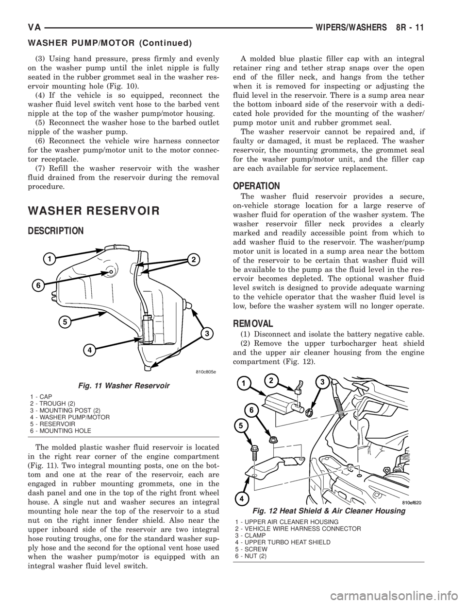
The molded plastic washer fluid reservoir is located
in the right rear corner of the engine compartment
(Fig. 11). Two integral mounting posts, one on the bot-
tom and one at the rear of the reservoir, each are
engaged in rubber mounting grommets, one in the
dash panel and one in the top of the right front wheel
house. A single nut and washer secures an integral
mounting hole near the top of the reservoir to a stud
nut on the right inner fender shield. Also near the
upper inboard side of the reservoir are two integral
hose routing troughs, one for the standard washer sup-
ply hose and the second for the optional vent hose used
when the washer pump/motor is equipped with an
integral washer fluid level switch.
A molded blue plastic filler cap with an integral
retainer ring and tether strap snaps over the open
end of the filler neck, and hangs from the tether
when it is removed for inspecting or adjusting the
fluid level in the reservoir. There is a sump area near
the bottom inboard side of the reservoir with a dedi-
cated hole provided for the mounting of the washer/
pump motor unit and rubber grommet seal.
The washer reservoir cannot be repaired and, if
faulty or damaged, it must be replaced. The washer
reservoir, the mounting grommets, the grommet seal
for the washer pump/motor unit, and the filler cap
are each available for service replacement.
OPERATION
The washer fluid reservoir provides a secure,
on-vehicle storage location for a large reserve of
washer fluid for operation of the washer system. The
washer reservoir filler neck provides a clearly
marked and readily accessible point from which to
add washer fluid to the reservoir. The washer/pump
motor unit is located in a sump area near the bottom
of the reservoir to be certain that washer fluid will
be available to the pump as the fluid level in the res-
ervoir becomes depleted. The optional washer fluid
level switch is designed to provide adequate warning
to the vehicle operator that the washer fluid level is
low, before the washer system will no longer operate.
REMOVAL
(1)Disconnect and isolate the battery negative cable.
(2) Remove the upper turbocharger heat shield
and the upper air cleaner housing from the engine
compartment (Fig. 12).
Fig. 11 Washer Reservoir
1 - CAP
2 - TROUGH (2)
3 - MOUNTING POST (2)
4 - WASHER PUMP/MOTOR
5 - RESERVOIR
6 - MOUNTING HOLE
Fig. 12 Heat Shield & Air Cleaner Housing
1 - UPPER AIR CLEANER HOUSING
2 - VEHICLE WIRE HARNESS CONNECTOR
3 - CLAMP
4 - UPPER TURBO HEAT SHIELD
5 - SCREW
6 - NUT (2)
VAWIPERS/WASHERS 8R - 11
WASHER PUMP/MOTOR (Continued)
Page 294 of 1232
(3) Disconnect the vehicle wire harness connector
for the washer pump/motor unit from the motor con-
nector receptacle.
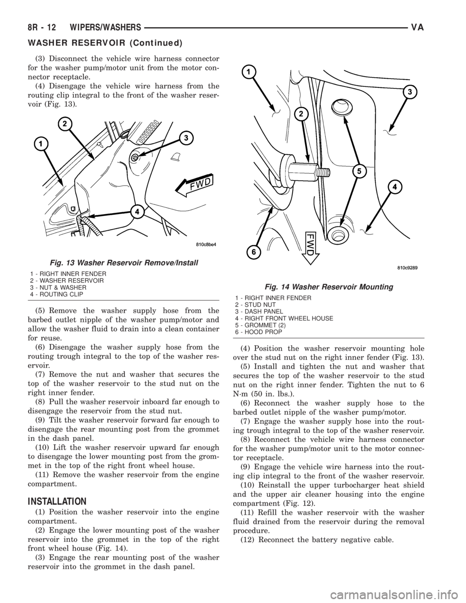
(4) Disengage the vehicle wire harness from the
routing clip integral to the front of the washer reser-
voir (Fig. 13).
(5) Remove the washer supply hose from the
barbed outlet nipple of the washer pump/motor and
allow the washer fluid to drain into a clean container
for reuse.
(6) Disengage the washer supply hose from the
routing trough integral to the top of the washer res-
ervoir.
(7) Remove the nut and washer that secures the
top of the washer reservoir to the stud nut on the
right inner fender.
(8) Pull the washer reservoir inboard far enough to
disengage the reservoir from the stud nut.
(9) Tilt the washer reservoir forward far enough to
disengage the rear mounting post from the grommet
in the dash panel.
(10) Lift the washer reservoir upward far enough
to disengage the lower mounting post from the grom-
met in the top of the right front wheel house.
(11) Remove the washer reservoir from the engine
compartment.
INSTALLATION
(1) Position the washer reservoir into the engine
compartment.
(2) Engage the lower mounting post of the washer
reservoir into the grommet in the top of the right
front wheel house (Fig. 14).
(3) Engage the rear mounting post of the washer
reservoir into the grommet in the dash panel.(4) Position the washer reservoir mounting hole
over the stud nut on the right inner fender (Fig. 13).
(5) Install and tighten the nut and washer that
secures the top of the washer reservoir to the stud
nut on the right inner fender. Tighten the nut to 6
N´m (50 in. lbs.).
(6) Reconnect the washer supply hose to the
barbed outlet nipple of the washer pump/motor.
(7) Engage the washer supply hose into the rout-
ing trough integral to the top of the washer reservoir.
(8) Reconnect the vehicle wire harness connector
for the washer pump/motor unit to the motor connec-
tor receptacle.
(9) Engage the vehicle wire harness into the rout-
ing clip integral to the front of the washer reservoir.
(10) Reinstall the upper turbocharger heat shield
and the upper air cleaner housing into the engine
compartment (Fig. 12).
(11) Refill the washer reservoir with the washer
fluid drained from the reservoir during the removal
procedure.
(12) Reconnect the battery negative cable.
Fig. 13 Washer Reservoir Remove/Install
1 - RIGHT INNER FENDER
2 - WASHER RESERVOIR
3 - NUT & WASHER
4 - ROUTING CLIP
Fig. 14 Washer Reservoir Mounting
1 - RIGHT INNER FENDER
2 - STUD NUT
3 - DASH PANEL
4 - RIGHT FRONT WHEEL HOUSE
5 - GROMMET (2)
6 - HOOD PROP
8R - 12 WIPERS/WASHERSVA
WASHER RESERVOIR (Continued)
Page 393 of 1232
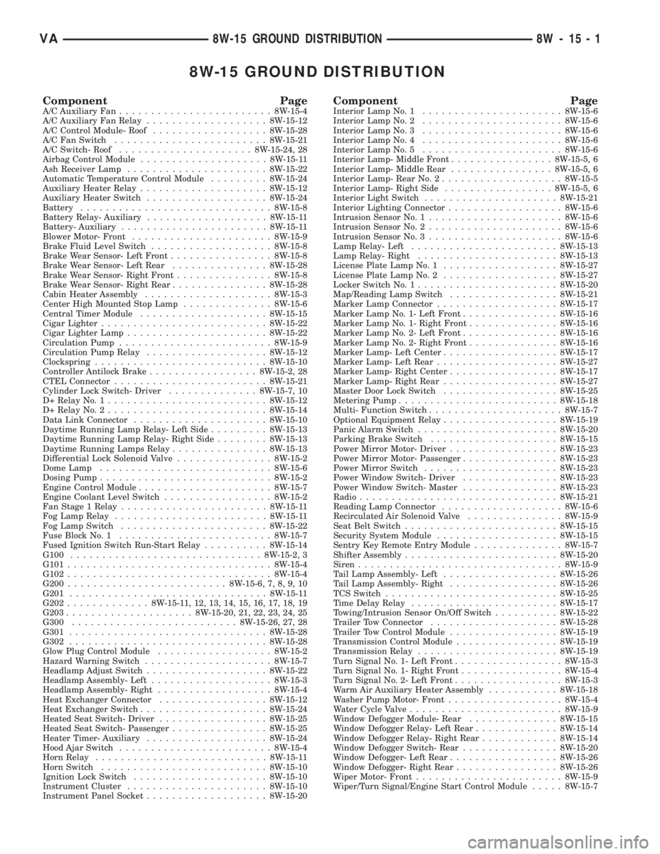
8W-15 GROUND DISTRIBUTION
Component PageA/C Auxiliary Fan........................8W-15-4
A/C Auxiliary Fan Relay...................8W-15-12
A/C Control Module- Roof..................8W-15-28
A/C Fan Switch........................8W-15-21
A/C Switch- Roof.....................8W-15-24, 28
Airbag Control Module....................8W-15-11
Ash Receiver Lamp......................8W-15-22
Automatic Temperature Control Module.........8W-15-24
Auxiliary Heater Relay....................8W-15-12
Auxiliary Heater Switch...................8W-15-24
Battery..............................8W-15-8
Battery Relay- Auxiliary...................8W-15-11
Battery- Auxiliary.......................8W-15-11
Blower Motor- Front......................8W-15-9
Brake Fluid Level Switch...................8W-15-8
Brake Wear Sensor- Left Front................8W-15-8
Brake Wear Sensor- Left Rear...............8W-15-28
Brake Wear Sensor- Right Front...............8W-15-8
Brake Wear Sensor- Right Rear...............8W-15-28
Cabin Heater Assembly....................8W-15-3
Center High Mounted Stop Lamp..............8W-15-6
Central Timer Module....................8W-15-15
Cigar Lighter..........................8W-15-22
Cigar Lighter Lamp......................8W-15-22
Circulation Pump........................8W-15-9
Circulation Pump Relay...................8W-15-12
Clockspring...........................8W-15-10
Controller Antilock Brake.................8W-15-2, 28
CTEL Connector........................8W-15-21
Cylinder Lock Switch- Driver..............8W-15-7, 10
D+ Relay No. 1.........................8W-15-12
D+ Relay No. 2.........................8W-15-14
Data Link Connector.....................8W-15-10
Daytime Running Lamp Relay- Left Side.........8W-15-13
Daytime Running Lamp Relay- Right Side........8W-15-13
Daytime Running Lamps Relay...............8W-15-13
Differential Lock Solenoid Valve...............8W-15-2
Dome Lamp...........................8W-15-6
Dosing Pump...........................8W-15-2
Engine Control Module.....................8W-15-7
Engine Coolant Level Switch.................8W-15-2
Fan Stage 1 Relay.......................8W-15-11
Fog Lamp Relay........................8W-15-11
Fog Lamp Switch.......................8W-15-22
Fuse Block No. 1........................8W-15-7
Fused Ignition Switch Run-Start Relay..........8W-15-14
G100..............................8W-15-2, 3
G101................................8W-15-4
G102................................8W-15-4
G200.........................8W-15-6, 7, 8, 9, 10
G201...............................8W-15-11
G202.............8W-15-11, 12, 13, 14, 15, 16, 17, 18, 19
G203....................8W-15-20, 21, 22, 23, 24, 25
G300..........................8W-15-26, 27, 28
G301...............................8W-15-28
G302...............................8W-15-28
Glow Plug Control Module..................8W-15-2
Hazard Warning Switch....................8W-15-7
Headlamp Adjust Switch...................8W-15-22
Headlamp Assembly- Left...................8W-15-3
Headlamp Assembly- Right..................8W-15-4
Heat Exchanger Connector.................8W-15-12
Heat Exchanger Switch....................8W-15-24
Heated Seat Switch- Driver.................8W-15-25
Heated Seat Switch- Passenger...............8W-15-25
Heater Timer- Auxiliary...................8W-15-24
Hood Ajar Switch........................8W-15-4
Horn Relay...........................8W-15-11
Horn Switch..........................8W-15-10
Ignition Lock Switch.....................8W-15-10
Instrument Cluster......................8W-15-10
Instrument Panel Socket...................8W-15-20Component PageInterior Lamp No. 1......................8W-15-6
Interior Lamp No. 2......................8W-15-6
Interior Lamp No. 3......................8W-15-6
Interior Lamp No. 4......................8W-15-6
Interior Lamp No. 5......................8W-15-6
Interior Lamp- Middle Front................8W-15-5, 6
Interior Lamp- Middle Rear................8W-15-5, 6
Interior Lamp- Rear No. 2...................8W-15-5
Interior Lamp- Right Side.................8W-15-5, 6
Interior Light Switch.....................8W-15-21
Interior Lighting Connector..................8W-15-6
Intrusion Sensor No. 1.....................8W-15-6
Intrusion Sensor No. 2.....................8W-15-6
Intrusion Sensor No. 3.....................8W-15-6
Lamp Relay- Left.......................8W-15-13
Lamp Relay- Right......................8W-15-13
License Plate Lamp No. 1..................8W-15-27
License Plate Lamp No. 2..................8W-15-27
Locker Switch No. 1......................8W-15-20
Map/Reading Lamp Switch.................8W-15-21
Marker Lamp Connector...................8W-15-17
Marker Lamp No. 1- Left Front...............8W-15-16
Marker Lamp No. 1- Right Front..............8W-15-16
Marker Lamp No. 2- Left Front...............8W-15-16
Marker Lamp No. 2- Right Front..............8W-15-16
Marker Lamp- Left Center..................8W-15-17
Marker Lamp- Left Rear...................8W-15-27
Marker Lamp- Right Center.................8W-15-17
Marker Lamp- Right Rear..................8W-15-27
Master Door Lock Switch..................8W-15-25
Metering Pump.........................8W-15-18
Multi- Function Switch.....................8W-15-7
Optional Equipment Relay..................8W-15-19
Panic Alarm Switch......................8W-15-20
Parking Brake Switch....................8W-15-15
Power Mirror Motor- Driver.................8W-15-23
Power Mirror Motor- Passenger...............8W-15-23
Power Mirror Switch.....................8W-15-23
Power Window Switch- Driver...............8W-15-23
Power Window Switch- Master...............8W-15-23
Radio...............................8W-15-21
Reading Lamp Connector...................8W-15-6
Recirculated Air Solenoid Valve...............8W-15-9
Seat Belt Switch........................8W-15-15
Security System Module...................8W-15-15
Sentry Key Remote Entry Module..............8W-15-7
Shifter Assembly........................8W-15-20
Siren................................8W-15-9
Tail Lamp Assembly- Left..................8W-15-26
Tail Lamp Assembly- Right.................8W-15-26
TCS Switch...........................8W-15-25
Time Delay Relay.......................8W-15-17
Towing/Intrusion Sensor On/Off Switch..........8W-15-22
Trailer Tow Connector....................8W-15-28
Trailer Tow Control Module.................8W-15-19
Transmission Control Module................8W-15-19
Transmission Relay......................8W-15-19
Turn Signal No. 1- Left Front.................8W-15-3
Turn Signal No. 1- Right Front................8W-15-4
Turn Signal No. 2- Left Front.................8W-15-3
Warm Air Auxiliary Heater Assembly...........8W-15-18
Washer Pump Motor- Front..................8W-15-4
Water Cycle Valve........................8W-15-9
Window Defogger Module- Rear..............8W-15-15
Window Defogger Relay- Left Rear.............8W-15-14
Window Defogger Relay- Right Rear............8W-15-14
Window Defogger Switch- Rear...............8W-15-20
Window Defogger- Left Rear.................8W-15-26
Window Defogger- Right Rear................8W-15-26
Wiper Motor- Front.......................8W-15-9
Wiper/Turn Signal/Engine Start Control Module.....8W-15-7
VA8W-15 GROUND DISTRIBUTION 8W - 15 - 1
Page 1211 of 1232
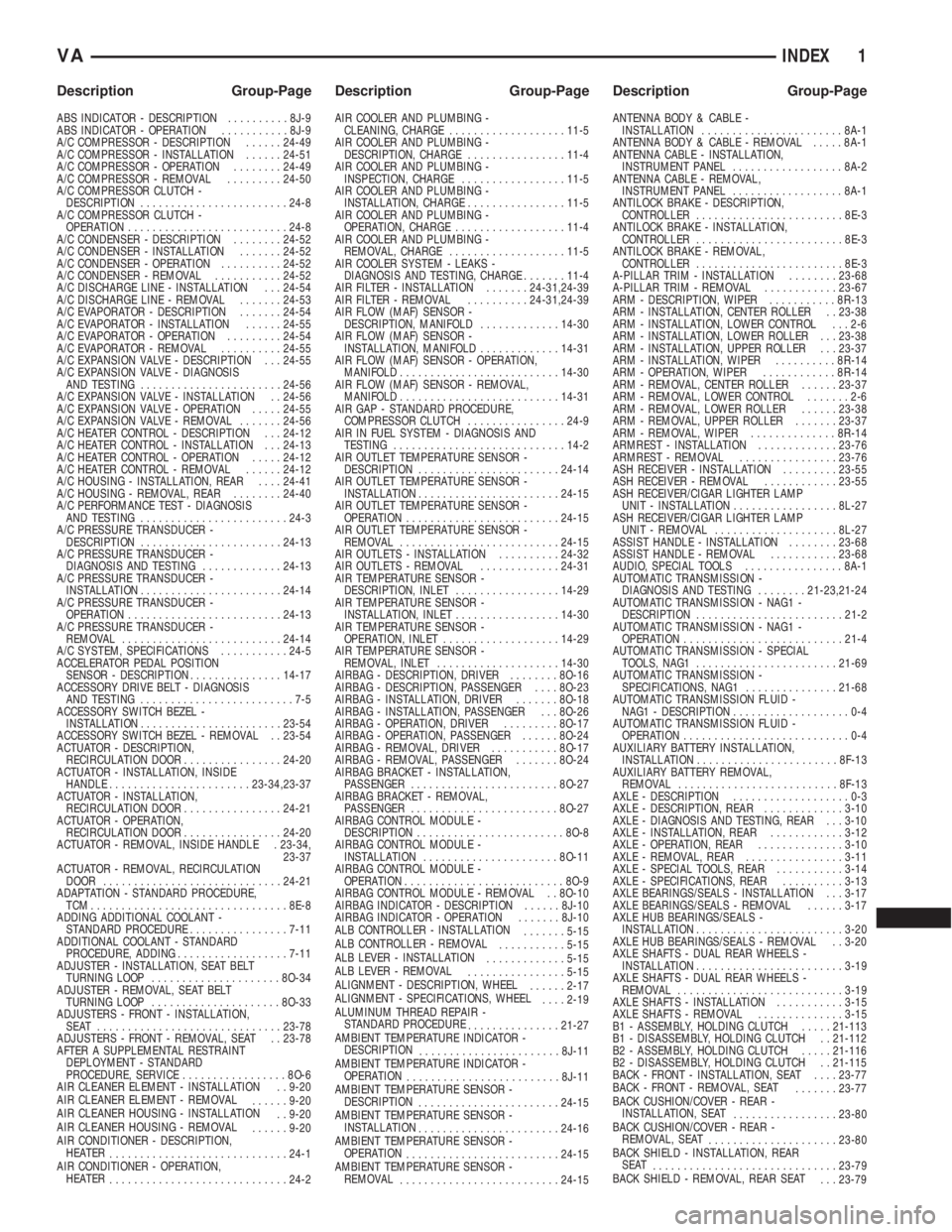
INDEX
ABS INDICATOR - DESCRIPTION..........8J-9
ABS INDICATOR - OPERATION...........8J-9
A/C COMPRESSOR - DESCRIPTION......24-49
A/C COMPRESSOR - INSTALLATION......24-51
A/C COMPRESSOR - OPERATION........24-49
A/C COMPRESSOR - REMOVAL.........24-50
A/C COMPRESSOR CLUTCH -
DESCRIPTION........................24-8
A/C COMPRESSOR CLUTCH -
OPERATION..........................24-8
A/C CONDENSER - DESCRIPTION........24-52
A/C CONDENSER - INSTALLATION.......24-52
A/C CONDENSER - OPERATION..........24-52
A/C CONDENSER - REMOVAL...........24-52
A/C DISCHARGE LINE - INSTALLATION . . . 24-54
A/C DISCHARGE LINE - REMOVAL.......24-53
A/C EVAPORATOR - DESCRIPTION.......24-54
A/C EVAPORATOR - INSTALLATION......24-55
A/C EVAPORATOR - OPERATION.........24-54
A/C EVAPORATOR - REMOVAL..........24-55
A/C EXPANSION VALVE - DESCRIPTION . . . 24-55
A/C EXPANSION VALVE - DIAGNOSIS
AND TESTING.......................24-56
A/C EXPANSION VALVE - INSTALLATION . . 24-56
A/C EXPANSION VALVE - OPERATION.....24-55
A/C EXPANSION VALVE - REMOVAL.......24-56
A/C HEATER CONTROL - DESCRIPTION . . . 24-12
A/C HEATER CONTROL - INSTALLATION . . . 24-13
A/C HEATER CONTROL - OPERATION.....24-12
A/C HEATER CONTROL - REMOVAL......24-12
A/C HOUSING - INSTALLATION, REAR....24-41
A/C HOUSING - REMOVAL, REAR........24-40
A/C PERFORMANCE TEST - DIAGNOSIS
AND TESTING........................24-3
A/C PRESSURE TRANSDUCER -
DESCRIPTION.......................24-13
A/C PRESSURE TRANSDUCER -
DIAGNOSIS AND TESTING.............24-13
A/C PRESSURE TRANSDUCER -
INSTALLATION.......................24-14
A/C PRESSURE TRANSDUCER -
OPERATION.........................24-13
A/C PRESSURE TRANSDUCER -
REMOVAL..........................24-14
A/C SYSTEM, SPECIFICATIONS...........24-5
ACCELERATOR PEDAL POSITION
SENSOR - DESCRIPTION...............14-17
ACCESSORY DRIVE BELT - DIAGNOSIS
AND TESTING.........................7-5
ACCESSORY SWITCH BEZEL -
INSTALLATION.......................23-54
ACCESSORY SWITCH BEZEL - REMOVAL . . 23-54
ACTUATOR - DESCRIPTION,
RECIRCULATION DOOR................24-20
ACTUATOR - INSTALLATION, INSIDE
HANDLE.......................23-34,23-37
ACTUATOR - INSTALLATION,
RECIRCULATION DOOR................24-21
ACTUATOR - OPERATION,
RECIRCULATION DOOR................24-20
ACTUATOR - REMOVAL, INSIDE HANDLE . 23-34,
23-37
ACTUATOR - REMOVAL, RECIRCULATION
DOOR.............................24-21
ADAPTATION - STANDARD PROCEDURE,
TCM................................8E-8
ADDING ADDITIONAL COOLANT -
STANDARD PROCEDURE................7-11
ADDITIONAL COOLANT - STANDARD
PROCEDURE, ADDING..................7-11
ADJUSTER - INSTALLATION, SEAT BELT
TURNING LOOP.....................8O-34
ADJUSTER - REMOVAL, SEAT BELT
TURNING LOOP.....................8O-33
ADJUSTERS - FRONT - INSTALLATION,
SEAT ..............................23-78
ADJUSTERS - FRONT - REMOVAL, SEAT . . 23-78
AFTER A SUPPLEMENTAL RESTRAINT
DEPLOYMENT - STANDARD
PROCEDURE, SERVICE.................8O-6
AIR CLEANER ELEMENT - INSTALLATION . . 9-20
AIR CLEANER ELEMENT - REMOVAL
......9-20
AIR CLEANER HOUSING - INSTALLATION
. . 9-20
AIR CLEANER HOUSING - REMOVAL
......9-20
AIR CONDITIONER - DESCRIPTION,
HEATER
.............................24-1
AIR CONDITIONER - OPERATION,
HEATER
.............................24-2AIR COOLER AND PLUMBING -
CLEANING, CHARGE...................11-5
AIR COOLER AND PLUMBING -
DESCRIPTION, CHARGE................11-4
AIR COOLER AND PLUMBING -
INSPECTION, CHARGE.................11-5
AIR COOLER AND PLUMBING -
INSTALLATION, CHARGE................11-5
AIR COOLER AND PLUMBING -
OPERATION, CHARGE..................11-4
AIR COOLER AND PLUMBING -
REMOVAL, CHARGE...................11-5
AIR COOLER SYSTEM - LEAKS -
DIAGNOSIS AND TESTING, CHARGE.......11-4
AIR FILTER - INSTALLATION.......24-31,24-39
AIR FILTER - REMOVAL..........24-31,24-39
AIR FLOW (MAF) SENSOR -
DESCRIPTION, MANIFOLD.............14-30
AIR FLOW (MAF) SENSOR -
INSTALLATION, MANIFOLD.............14-31
AIR FLOW (MAF) SENSOR - OPERATION,
MANIFOLD..........................14-30
AIR FLOW (MAF) SENSOR - REMOVAL,
MANIFOLD..........................14-31
AIR GAP - STANDARD PROCEDURE,
COMPRESSOR CLUTCH................24-9
AIR IN FUEL SYSTEM - DIAGNOSIS AND
TESTING............................14-2
AIR OUTLET TEMPERATURE SENSOR -
DESCRIPTION.......................24-14
AIR OUTLET TEMPERATURE SENSOR -
INSTALLATION.......................24-15
AIR OUTLET TEMPERATURE SENSOR -
OPERATION.........................24-15
AIR OUTLET TEMPERATURE SENSOR -
REMOVAL..........................24-15
AIR OUTLETS - INSTALLATION..........24-32
AIR OUTLETS - REMOVAL.............24-31
AIR TEMPERATURE SENSOR -
DESCRIPTION, INLET.................14-29
AIR TEMPERATURE SENSOR -
INSTALLATION, INLET.................14-30
AIR TEMPERATURE SENSOR -
OPERATION, INLET...................14-29
AIR TEMPERATURE SENSOR -
REMOVAL, INLET....................14-30
AIRBAG - DESCRIPTION, DRIVER........8O-16
AIRBAG - DESCRIPTION, PASSENGER....8O-23
AIRBAG - INSTALLATION, DRIVER.......8O-18
AIRBAG - INSTALLATION, PASSENGER . . . 8O-26
AIRBAG - OPERATION, DRIVER.........8O-17
AIRBAG - OPERATION, PASSENGER......8O-24
AIRBAG - REMOVAL, DRIVER...........8O-17
AIRBAG - REMOVAL, PASSENGER.......8O-24
AIRBAG BRACKET - INSTALLATION,
PASSENGER........................8O-27
AIRBAG BRACKET - REMOVAL,
PASSENGER........................8O-27
AIRBAG CONTROL MODULE -
DESCRIPTION........................8O-8
AIRBAG CONTROL MODULE -
INSTALLATION......................8O-11
AIRBAG CONTROL MODULE -
OPERATION..........................8O-9
AIRBAG CONTROL MODULE - REMOVAL . . 8O-10
AIRBAG INDICATOR - DESCRIPTION......8J-10
AIRBAG INDICATOR - OPERATION.......8J-10
ALB CONTROLLER - INSTALLATION
.......5-15
ALB CONTROLLER - REMOVAL
...........5-15
ALB LEVER - INSTALLATION
.............5-15
ALB LEVER - REMOVAL
................5-15
ALIGNMENT - DESCRIPTION, WHEEL
......2-17
ALIGNMENT - SPECIFICATIONS, WHEEL
....2-19
ALUMINUM THREAD REPAIR -
STANDARD PROCEDURE
...............21-27
AMBIENT TEMPERATURE INDICATOR -
DESCRIPTION
.......................8J-11
AMBIENT TEMPERATURE INDICATOR -
OPERATION
.........................8J-11
AMBIENT TEMPERATURE SENSOR -
DESCRIPTION
.......................24-15
AMBIENT TEMPERATURE SENSOR -
INSTALLATION
.......................24-16
AMBIENT TEMPERATURE SENSOR -
OPERATION
.........................24-15
AMBIENT TEMPERATURE SENSOR -
REMOVAL
..........................24-15ANTENNA BODY & CABLE -
INSTALLATION.......................8A-1
ANTENNA BODY & CABLE - REMOVAL.....8A-1
ANTENNA CABLE - INSTALLATION,
INSTRUMENT PANEL..................8A-2
ANTENNA CABLE - REMOVAL,
INSTRUMENT PANEL..................8A-1
ANTILOCK BRAKE - DESCRIPTION,
CONTROLLER........................8E-3
ANTILOCK BRAKE - INSTALLATION,
CONTROLLER........................8E-3
ANTILOCK BRAKE - REMOVAL,
CONTROLLER........................8E-3
A-PILLAR TRIM - INSTALLATION........23-68
A-PILLAR TRIM - REMOVAL............23-67
ARM - DESCRIPTION, WIPER...........8R-13
ARM - INSTALLATION, CENTER ROLLER . . 23-38
ARM - INSTALLATION, LOWER CONTROL . . . 2-6
ARM - INSTALLATION, LOWER ROLLER . . . 23-38
ARM - INSTALLATION, UPPER ROLLER . . . 23-37
ARM - INSTALLATION, WIPER..........8R-14
ARM - OPERATION, WIPER............8R-14
ARM - REMOVAL, CENTER ROLLER......23-37
ARM - REMOVAL, LOWER CONTROL.......2-6
ARM - REMOVAL, LOWER ROLLER......23-38
ARM - REMOVAL, UPPER ROLLER.......23-37
ARM - REMOVAL, WIPER..............8R-14
ARMREST - INSTALLATION.............23-76
ARMREST - REMOVAL................23-76
ASH RECEIVER - INSTALLATION.........23-55
ASH RECEIVER - REMOVAL............23-55
ASH RECEIVER/CIGAR LIGHTER LAMP
UNIT - INSTALLATION.................8L-27
ASH RECEIVER/CIGAR LIGHTER LAMP
UNIT - REMOVAL....................8L-27
ASSIST HANDLE - INSTALLATION........23-68
ASSIST HANDLE - REMOVAL...........23-68
AUDIO, SPECIAL TOOLS................8A-1
AUTOMATIC TRANSMISSION -
DIAGNOSIS AND TESTING........21-23,21-24
AUTOMATIC TRANSMISSION - NAG1 -
DESCRIPTION........................21-2
AUTOMATIC TRANSMISSION - NAG1 -
OPERATION..........................21-4
AUTOMATIC TRANSMISSION - SPECIAL
TOOLS, NAG1.......................21-69
AUTOMATIC TRANSMISSION -
SPECIFICATIONS, NAG1...............21-68
AUTOMATIC TRANSMISSION FLUID -
NAG1 - DESCRIPTION...................0-4
AUTOMATIC TRANSMISSION FLUID -
OPERATION...........................0-4
AUXILIARY BATTERY INSTALLATION,
INSTALLATION.......................8F-13
AUXILIARY BATTERY REMOVAL,
REMOVAL..........................8F-13
AXLE - DESCRIPTION...................0-3
AXLE - DESCRIPTION, REAR.............3-10
AXLE - DIAGNOSIS AND TESTING, REAR . . . 3-10
AXLE - INSTALLATION, REAR............3-12
AXLE - OPERATION, REAR..............3-10
AXLE - REMOVAL, REAR................3-11
AXLE - SPECIAL TOOLS, REAR...........3-14
AXLE - SPECIFICATIONS, REAR..........3-13
AXLE BEARINGS/SEALS - INSTALLATION . . . 3-17
AXLE BEARINGS/SEALS - REMOVAL......3-17
AXLE HUB BEARINGS/SEALS -
INSTALLATION........................3-20
AXLE HUB BEARINGS/SEALS - REMOVAL . . 3-20
AXLE SHAFTS - DUAL REAR WHEELS -
INSTALLATION........................3-19
AXLE SHAFTS - DUAL REAR WHEELS -
REMOVAL...........................3-19
AXLE SHAFTS - INSTALLATION...........3-15
AXLE SHAFTS - REMOVAL..............3-15
B1 - ASSEMBLY, HOLDING CLUTCH.....21-113
B1 - DISASSEMBLY, HOLDING CLUTCH . . 21-112
B2 - ASSEMBLY, HOLDING CLUTCH.....21-116
B2 - DISASSEMBLY, HOLDING CLUTCH . . 21-115
BACK - FRONT - INSTALLATION, SEAT....23-77
BACK - FRONT - REMOVAL, SEAT
.......23-77
BACK CUSHION/COVER - REAR -
INSTALLATION, SEAT
.................23-80
BACK CUSHION/COVER - REAR -
REMOVAL, SEAT
.....................23-80
BACK SHIELD - INSTALLATION, REAR
SEAT
..............................23-79
BACK SHIELD - REMOVAL, REAR SEAT
. . . 23-79
VAINDEX 1
Description Group-Page Description Group-Page Description Group-Page
Page 1212 of 1232
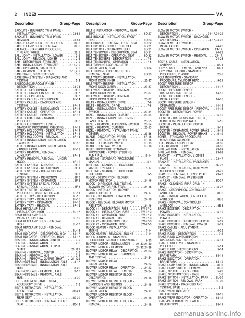
BACKLITE - BULKHEAD TRIM PANEL -
INSTALLATION.......................23-81
BACKLITE - BULKHEAD TRIM PANEL -
REMOVAL..........................23-81
BACKUP LAMP BULB - INSTALLATION.....8L-6
BACKUP LAMP BULB - REMOVAL........8L-5
BALANCE - STANDARD PROCEDURE,
TIRE AND WHEEL.....................22-3
BALL JOINT - INSTALLATION, LOWER......2-6
BALL JOINT - REMOVAL, LOWER..........2-6
BAR - DESCRIPTION, STABILIZER.........2-9
BAR - INSTALLATION, STABILIZER.....2-15,2-9
BAR - OPERATION, STABILIZER...........2-9
BAR - REMOVAL, STABILIZER........2-15,2-9
BASE BRAKE, SPECIFICATIONS............5-6
BASE BRAKE SYSTEM - DIAGNOSIS AND
TESTING.............................5-2
BASECOAT/CLEARCOAT FINISH -
DESCRIPTION.......................23-74
BATTERY - DESCRIPTION...............8F-6
BATTERY - DIAGNOSIS AND TESTING.....8F-7
BATTERY - OPERATION.................8F-7
BATTERY CABLES - DESCRIPTION.......8F-14
BATTERY CABLES - DIAGNOSIS AND
TESTING...........................8F-14
BATTERY CABLES - INSTALLATION.......8F-16
BATTERY CABLES - OPERATION.........8F-14
BATTERY CABLES - REMOVAL..........8F-16
BATTERY CHARGING - STANDARD
PROCEDURE.........................8F-8
BATTERY ELECTROLYTE LEVEL -
STANDARD PROCEDURE, CHECKING.....8F-12
BATTERY HOLDDOWN - DESCRIPTION....8F-14
BATTERY HOLDDOWN - INSTALLATION . . . 8F-14
BATTERY HOLDDOWN - REMOVAL.......8F-14
BATTERY INSTALLATION, INSTALLATION
- AUXILIARY........................8F-13
BATTERY INSTALLATION, INSTALLATION
- UNDER HOOD......................8F-13
BATTERY REMOVAL, REMOVAL -
AUXILIARY..........................8F-13
BATTERY REMOVAL, REMOVAL - UNDER
HOOD..............................8F-12
BATTERY SYSTEM - CLEANING...........8F-5
BATTERY SYSTEM - DESCRIPTION........8F-1
BATTERY SYSTEM - DIAGNOSIS AND
TESTING............................8F-2
BATTERY SYSTEM - INSPECTION.........8F-6
BATTERY SYSTEM - OPERATION.........8F-2
BATTERY SYSTEM SPECIAL TOOLS,
SPECIAL TOOLS......................8F-6
BATTERY TESTER - STANDARD
PROCEDURE, USING MICRO 420........8F-11
BATTERY TRAY - DESCRIPTION.........8F-16
BATTERY TRAY - INSTALLATION.........8F-16
BATTERY TRAY - OPERATION...........8F-16
BATTERY TRAY - REMOVAL............8F-16
BEAM HEADLAMP BULB -
INSTALLATION, HIGH.................8L-17
BEAM HEADLAMP BULB -
INSTALLATION, LOW..................8L-19
BEAM HEADLAMP BULB - REMOVAL,
HIGH..............................8L-17
BEAM HEADLAMP BULB - REMOVAL,
LOW ..............................8L-18
BEAM INDICATOR - DESCRIPTION, HIGH . . 8J-17
BEAM INDICATOR - OPERATION, HIGH....8J-17
BEARING - INSTALLATION, CENTER........3-9
BEARING - INSTALLATION, HUB...........2-5
BEARING - INSTALLATION, OUTPUT
SHAFT............................21-122
BEARING - REMOVAL, CENTER...........3-8
BEARING - REMOVAL, HUB..............2-4
BEARING - REMOVAL, OUTPUT SHAFT . . . 21-122
BEARINGS/SEALS - INSTALLATION, AXLE . . 3-17
BEARINGS/SEALS - INSTALLATION, AXLE
HUB................................3-20
BEARINGS/SEALS - REMOVAL, AXLE......3-17
BEARINGS/SEALS - REMOVAL, AXLE
HUB
................................3-20
BELT - DIAGNOSIS AND TESTING,
ACCESSORY DRIVE
.....................7-5
BELT & RETRACTOR - INSTALLATION,
FRONT SEAT
........................8O-21
BELT & RETRACTOR - INSTALLATION,
REAR SEAT
.........................8O-29
BELT & RETRACTOR - REMOVAL, FRONT
SEAT
..............................8O-19BELT & RETRACTOR - REMOVAL, REAR
SEAT ..............................8O-27
BELT BUCKLE - INSTALLATION, FRONT
SEAT ..............................8O-23
BELT BUCKLE - REMOVAL, FRONT SEAT . . 8O-22
BELT SWITCH - DESCRIPTION, SEAT.....8O-31
BELT SWITCH - OPERATION, SEAT.......8O-31
BELT TENSIONER - DESCRIPTION, SEAT . . 8O-31
BELT TENSIONER - OPERATION, SEAT....8O-32
BELT TENSIONERS - DESCRIPTION........7-5
BELT TENSIONERS - OPERATION..........7-5
BELT TURNING LOOP ADJUSTER -
INSTALLATION, SEAT.................8O-34
BELT TURNING LOOP ADJUSTER -
REMOVAL, SEAT.....................8O-33
BELT WEATHERSTRIP - INSTALLATION,
FRONT DOOR INNER..................23-87
BELT WEATHERSTRIP - INSTALLATION,
FRONT DOOR OUTER.................23-87
BELT WEATHERSTRIP - REMOVAL,
FRONT DOOR INNER..................23-87
BELT WEATHERSTRIP - REMOVAL,
FRONT DOOR OUTER.................23-87
BELTS - INSTALLATION, DRIVE............7-8
BELTS - REMOVAL, DRIVE...............7-8
BEZEL - INSTALLATION, ACCESSORY
SWITCH............................23-54
BEZEL - INSTALLATION, CLUSTER.......23-54
BEZEL - INSTALLATION, INSTRUMENT
PANEL CENTER......................23-55
BEZEL - REMOVAL, ACCESSORY SWITCH . 23-54
BEZEL - REMOVAL, CLUSTER...........23-53
BEZEL - REMOVAL, INSTRUMENT PANEL
CENTER............................23-55
BLADE - DESCRIPTION, WIPER.........8R-15
BLADE - INSTALLATION, WIPER.........8R-16
BLADE - OPERATION, WIPER...........8R-15
BLADE - REMOVAL, WIPER............8R-16
BLEED PROCEDURE, STANDARD
PROCEDURE - POWER STEERING
PUMP FILL.........................19-14
BLEEDING - STANDARD PROCEDURE,
MANUAL.............................5-4
BLEEDING - STANDARD PROCEDURE,
MASTER CYLINDER...................5-17
BLEEDING - STANDARD PROCEDURE,
PRESSURE...........................5-5
BLOCK - DESCRIPTION, BLOWER
MOTOR RESISTOR...................24-16
BLOCK - DIAGNOSIS AND TESTING,
BLOWER MOTOR RESISTOR............24-16
BLOCK - INSTALLATION, BLOWER
MOTOR RESISTOR...................24-17
BLOCK - OPERATION, BLOWER MOTOR
RESISTOR..........................24-16
BLOCK - REMOVAL, BLOWER MOTOR
RESISTOR..........................24-16
BLOCK #1 - DESCRIPTION, FUSE......8W-97-2
BLOCK #1 - INSTALLATION, FUSE.....8W-97-3
BLOCK #1 - OPERATION, FUSE.......8W-97-2
BLOCK #1 - REMOVAL, FUSE.........8W-97-3
BLOCK #2 - DESCRIPTION, FUSE......8W-97-3
BLOCK #2 - OPERATION, FUSE.......8W-97-3
BLOCK HEATER - INSTALLATION,
ENGINE.............................7-14
BLOCK HEATER - REMOVAL, ENGINE......7-14
BLOCK JOURNALS - STANDARD
PROCEDURE, MEASURE CRANKSHAFT
....9-35
BLOWER MOTOR - INSTALLATION
. . 24-33,24-40
BLOWER MOTOR - REMOVAL
......24-32,24-39
BLOWER MOTOR RELAY - DESCRIPTION
. . 24-23
BLOWER MOTOR RELAY - DIAGNOSIS
AND TESTING
.......................24-24
BLOWER MOTOR RELAY -
INSTALLATION
.......................24-24
BLOWER MOTOR RELAY - OPERATION
. . . 24-23
BLOWER MOTOR RELAY - REMOVAL
.....24-24
BLOWER MOTOR RESISTOR BLOCK -
DESCRIPTION
.......................24-16
BLOWER MOTOR RESISTOR BLOCK -
DIAGNOSIS AND TESTING
.............24-16
BLOWER MOTOR RESISTOR BLOCK -
INSTALLATION
.......................24-17
BLOWER MOTOR RESISTOR BLOCK -
OPERATION
.........................24-16
BLOWER MOTOR RESISTOR BLOCK -
REMOVAL
..........................24-16BLOWER MOTOR SWITCH -
DESCRIPTION..................24-17,24-22
BLOWER MOTOR SWITCH - DIAGNOSIS
AND TESTING..................24-17,24-23
BLOWER MOTOR SWITCH -
INSTALLATION.......................24-23
BLOWER MOTOR SWITCH - OPERATION . . 24-17,
24-22
BLOWER MOTOR SWITCH - REMOVAL . . . 24-17,
24-23
BODY & CABLE - INSTALLATION,
ANTENNA...........................8A-1
BODY & CABLE - REMOVAL, ANTENNA....8A-1
BODY PANEL REPAIR - STANDARD
PROCEDURE, PLASTIC.................23-3
BOLT INSPECTION - STANDARD
PROCEDURE, CYLINDER HEAD...........9-21
BOOST PRESSURE SENSOR -
DESCRIPTION.......................14-17
BOOST PRESSURE SENSOR -
DIAGNOSIS AND TESTING.............14-18
BOOST PRESSURE SENSOR -
INSTALLATION.......................14-18
BOOST PRESSURE SENSOR -
OPERATION.........................14-18
BOOST PRESSURE SENSOR - REMOVAL . . 14-18
BOOSTER - DESCRIPTION, POWER
BRAKE..............................5-19
BOOSTER - DIAGNOSIS AND TESTING,
MASTER CYLINDER/POWER.............5-16
BOOSTER - INSTALLATION, POWER
BRAKE..............................5-19
BOOSTER - OPERATION, POWER BRAKE....5-19
BOOSTER - REMOVAL, POWER BRAKE....5-19
BORES - STANDARD PROCEDURE,
MEASURING CYLINDER................9-34
BOX - INSTALLATION, GLOVE...........23-56
BOX - REMOVAL, GLOVE..............23-56
B-PILLAR TRIM - INSTALLATION........23-69
B-PILLAR TRIM - REMOVAL............23-68
BRACKET - INSTALLATION, LICENSE
PLATE .............................23-47
BRACKET - INSTALLATION, PASSENGER
AIRBAG............................8O-27
BRACKET - INSTALLATION, REAR VIEW
MIRROR SUPPORT...................23-72
BRACKET - REMOVAL, LICENSE PLATE . . . 23-47
BRACKET - REMOVAL, PASSENGER
AIRBAG............................8O-27
BRAKE - CLEANING, REAR DRUM IN
HAT ................................5-27
BRAKE - DESCRIPTION, CONTROLLER
ANTILOCK...........................8E-3
BRAKE - INSTALLATION, CONTROLLER
ANTILOCK...........................8E-3
BRAKE - REMOVAL, CONTROLLER
ANTILOCK...........................8E-3
BRAKE BOOSTER - DESCRIPTION,
POWER.............................5-19
BRAKE BOOSTER - INSTALLATION,
POWER.............................5-19
BRAKE BOOSTER - OPERATION, POWER . . . 5-19
BRAKE BOOSTER - REMOVAL, POWER....5-19
BRAKE CABLES - ADJUSTMENT,
PARKING............................5-25
BRAKE FLUID - DESCRIPTION............0-3
BRAKE FLUID CONTAMINATION -
DIAGNOSIS AND TESTING..............5-14
BRAKE FLUID LEVEL - STANDARD
PROCEDURE.........................5-14
BRAKE FLUID, SPECIFICATIONS..........5-14
BRAKE INDICATOR - DESCRIPTION,
BRAKE/PARK........................8J-11
BRAKE INDICATOR - OPERATION,
BRAKE/PARK........................8J-12
BRAKE LAMP SWITCH - INSTALLATION....8L-6
BRAKE LAMP SWITCH - REMOVAL.......8L-6
BRAKE, SPECIAL TOOLS - PARK.........5-23
BRAKE, SPECIFICATIONS - BASE..........5-6
BRAKE SWITCH - INSTALLATION, PARK . . . 8L-20
BRAKE SWITCH - REMOVAL, PARK
......8L-20
BRAKE SYSTEM - DIAGNOSIS AND
TESTING, BASE
........................5-2
BRAKE WEAR INDICATOR -
DESCRIPTION
.......................8J-12
BRAKE WEAR INDICATOR - OPERATION
. . . 8J-12
BRAKE/PARK BRAKE INDICATOR -
DESCRIPTION
.......................8J-11
2 INDEXVA
Description Group-Page Description Group-Page Description Group-Page
Page 1220 of 1232
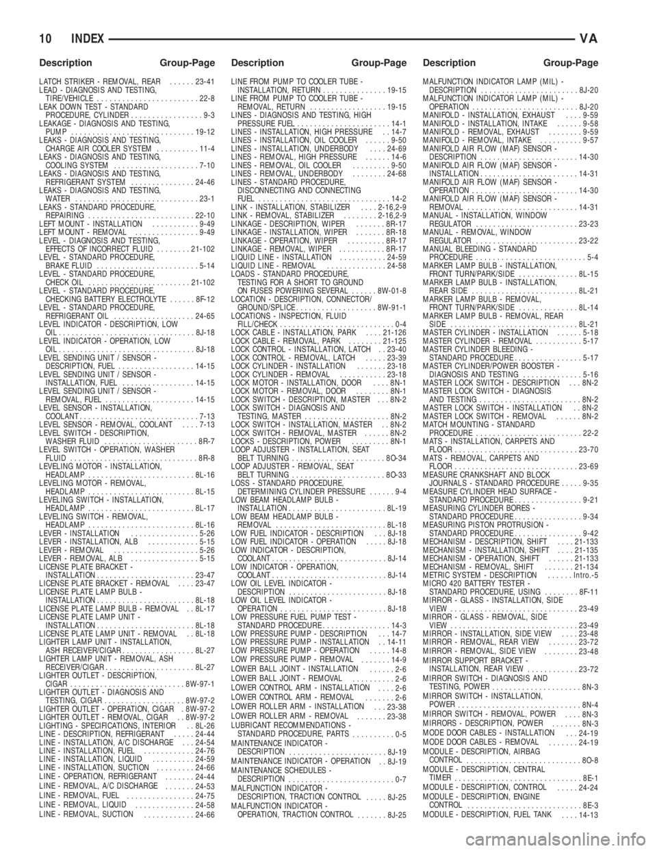
LATCH STRIKER - REMOVAL, REAR......23-41
LEAD - DIAGNOSIS AND TESTING,
TIRE/VEHICLE........................22-8
LEAK DOWN TEST - STANDARD
PROCEDURE, CYLINDER.................9-3
LEAKAGE - DIAGNOSIS AND TESTING,
PUMP.............................19-12
LEAKS - DIAGNOSIS AND TESTING,
CHARGE AIR COOLER SYSTEM..........11-4
LEAKS - DIAGNOSIS AND TESTING,
COOLING SYSTEM....................7-10
LEAKS - DIAGNOSIS AND TESTING,
REFRIGERANT SYSTEM...............24-46
LEAKS - DIAGNOSIS AND TESTING,
WATER .............................23-1
LEAKS - STANDARD PROCEDURE,
REPAIRING.........................22-10
LEFT MOUNT - INSTALLATION...........9-49
LEFT MOUNT - REMOVAL...............9-49
LEVEL - DIAGNOSIS AND TESTING,
EFFECTS OF INCORRECT FLUID........21-102
LEVEL - STANDARD PROCEDURE,
BRAKE FLUID........................5-14
LEVEL - STANDARD PROCEDURE,
CHECK OIL........................21-102
LEVEL - STANDARD PROCEDURE,
CHECKING BATTERY ELECTROLYTE......8F-12
LEVEL - STANDARD PROCEDURE,
REFRIGERANT OIL...................24-65
LEVEL INDICATOR - DESCRIPTION, LOW
OIL................................8J-18
LEVEL INDICATOR - OPERATION, LOW
OIL.................................8J-18
LEVEL SENDING UNIT / SENSOR -
DESCRIPTION, FUEL..................14-15
LEVEL SENDING UNIT / SENSOR -
INSTALLATION, FUEL.................14-15
LEVEL SENDING UNIT / SENSOR -
REMOVAL, FUEL.....................14-15
LEVEL SENSOR - INSTALLATION,
COOLANT............................7-13
LEVEL SENSOR - REMOVAL, COOLANT....7-13
LEVEL SWITCH - DESCRIPTION,
WASHER FLUID......................8R-7
LEVEL SWITCH - OPERATION, WASHER
FLUID..............................8R-8
LEVELING MOTOR - INSTALLATION,
HEADLAMP.........................8L-16
LEVELING MOTOR - REMOVAL,
HEADLAMP.........................8L-15
LEVELING SWITCH - INSTALLATION,
HEADLAMP.........................8L-17
LEVELING SWITCH - REMOVAL,
HEADLAMP.........................8L-16
LEVER - INSTALLATION................5-26
LEVER - INSTALLATION, ALB............5-15
LEVER - REMOVAL....................5-26
LEVER - REMOVAL, ALB................5-15
LICENSE PLATE BRACKET -
INSTALLATION.......................23-47
LICENSE PLATE BRACKET - REMOVAL....23-47
LICENSE PLATE LAMP BULB -
INSTALLATION.......................8L-18
LICENSE PLATE LAMP BULB - REMOVAL . . 8L-17
LICENSE PLATE LAMP UNIT -
INSTALLATION.......................8L-18
LICENSE PLATE LAMP UNIT - REMOVAL . . 8L-18
LIGHTER LAMP UNIT - INSTALLATION,
ASH RECEIVER/CIGAR.................8L-27
LIGHTER LAMP UNIT - REMOVAL, ASH
RECEIVER/CIGAR.....................8L-27
LIGHTER OUTLET - DESCRIPTION,
CIGAR...........................8W-97-1
LIGHTER OUTLET - DIAGNOSIS AND
TESTING, CIGAR...................8W-97-2
LIGHTER OUTLET - OPERATION, CIGAR . 8W-97-2
LIGHTER OUTLET - REMOVAL, CIGAR . . 8W-97-2
LIGHTING - SPECIFICATIONS, INTERIOR . . 8L-26
LINE - DESCRIPTION, REFRIGERANT.....24-44
LINE - INSTALLATION, A/C DISCHARGE . . . 24-54
LINE - INSTALLATION, FUEL............24-76
LINE - INSTALLATION, LIQUID..........24-59
LINE - INSTALLATION, SUCTION.........24-66
LINE - OPERATION, REFRIGERANT
.......24-44
LINE - REMOVAL, A/C DISCHARGE
.......24-53
LINE - REMOVAL, FUEL
................24-75
LINE - REMOVAL, LIQUID
..............24-58
LINE - REMOVAL, SUCTION
............24-66LINE FROM PUMP TO COOLER TUBE -
INSTALLATION, RETURN...............19-15
LINE FROM PUMP TO COOLER TUBE -
REMOVAL, RETURN..................19-15
LINES - DIAGNOSIS AND TESTING, HIGH
PRESSURE FUEL......................14-1
LINES - INSTALLATION, HIGH PRESSURE . . 14-7
LINES - INSTALLATION, OIL COOLER......9-50
LINES - INSTALLATION, UNDERBODY....24-69
LINES - REMOVAL, HIGH PRESSURE......14-6
LINES - REMOVAL, OIL COOLER.........9-50
LINES - REMOVAL, UNDERBODY........24-68
LINES - STANDARD PROCEDURE,
DISCONNECTING AND CONNECTING
FUEL...............................14-2
LINK - INSTALLATION, STABILIZER....2-16,2-9
LINK - REMOVAL, STABILIZER........2-16,2-9
LINKAGE - DESCRIPTION, WIPER.......8R-17
LINKAGE - INSTALLATION, WIPER.......8R-18
LINKAGE - OPERATION, WIPER.........8R-17
LINKAGE - REMOVAL, WIPER...........8R-17
LIQUID LINE - INSTALLATION...........24-59
LIQUID LINE - REMOVAL..............24-58
LOADS - STANDARD PROCEDURE,
TESTING FOR A SHORT TO GROUND
ON FUSES POWERING SEVERAL......8W-01-8
LOCATION - DESCRIPTION, CONNECTOR/
GROUND/SPLICE...................8W-91-1
LOCATIONS - INSPECTION, FLUID
FILL/CHECK............................0-4
LOCK CABLE - INSTALLATION, PARK....21-126
LOCK CABLE - REMOVAL, PARK........21-125
LOCK CONTROL - INSTALLATION, LATCH . . 23-40
LOCK CONTROL - REMOVAL, LATCH.....23-39
LOCK CYLINDER - INSTALLATION.......23-18
LOCK CYLINDER - REMOVAL...........23-18
LOCK MOTOR - INSTALLATION, DOOR....8N-1
LOCK MOTOR - REMOVAL, DOOR........8N-1
LOCK SWITCH - DESCRIPTION, MASTER . . . 8N-2
LOCK SWITCH - DIAGNOSIS AND
TESTING, MASTER....................8N-2
LOCK SWITCH - INSTALLATION, MASTER . . 8N-2
LOCK SWITCH - REMOVAL, MASTER......8N-2
LOCKS - DESCRIPTION, POWER.........8N-1
LOOP ADJUSTER - INSTALLATION, SEAT
BELT TURNING......................8O-34
LOOP ADJUSTER - REMOVAL, SEAT
BELT TURNING......................8O-33
LOSS - STANDARD PROCEDURE,
DETERMINING CYLINDER PRESSURE......9-4
LOW BEAM HEADLAMP BULB -
INSTALLATION.......................8L-19
LOW BEAM HEADLAMP BULB -
REMOVAL..........................8L-18
LOW FUEL INDICATOR - DESCRIPTION . . . 8J-18
LOW FUEL INDICATOR - OPERATION.....8J-18
LOW INDICATOR - DESCRIPTION,
COOLANT...........................8J-14
LOW INDICATOR - OPERATION,
COOLANT...........................8J-14
LOW OIL LEVEL INDICATOR -
DESCRIPTION.......................8J-18
LOW OIL LEVEL INDICATOR -
OPERATION.........................8J-18
LOW PRESSURE FUEL PUMP TEST -
STANDARD PROCEDURE................14-3
LOW PRESSURE PUMP - DESCRIPTION . . . 14-7
LOW PRESSURE PUMP - INSTALLATION . . 14-11
LOW PRESSURE PUMP - OPERATION.....14-8
LOW PRESSURE PUMP - REMOVAL
.......14-9
LOWER BALL JOINT - INSTALLATION
......2-6
LOWER BALL JOINT - REMOVAL
..........2-6
LOWER CONTROL ARM - INSTALLATION
....2-6
LOWER CONTROL ARM - REMOVAL
.......2-6
LOWER ROLLER ARM - INSTALLATION
. . . 23-38
LOWER ROLLER ARM - REMOVAL
.......23-38
LUBRICANT RECOMMENDATIONS -
STANDARD PROCEDURE, PARTS
..........0-5
MAINTENANCE INDICATOR -
DESCRIPTION
.......................8J-19
MAINTENANCE INDICATOR - OPERATION
. . 8J-19
MAINTENANCE SCHEDULES -
DESCRIPTION
.........................0-7
MALFUNCTION INDICATOR -
DESCRIPTION, TRACTION CONTROL
.....8J-25
MALFUNCTION INDICATOR -
OPERATION, TRACTION CONTROL
.......8J-25MALFUNCTION INDICATOR LAMP (MIL) -
DESCRIPTION.......................8J-20
MALFUNCTION INDICATOR LAMP (MIL) -
OPERATION.........................8J-20
MANIFOLD - INSTALLATION, EXHAUST....9-59
MANIFOLD - INSTALLATION, INTAKE......9-58
MANIFOLD - REMOVAL, EXHAUST........9-59
MANIFOLD - REMOVAL, INTAKE..........9-57
MANIFOLD AIR FLOW (MAF) SENSOR -
DESCRIPTION.......................14-30
MANIFOLD AIR FLOW (MAF) SENSOR -
INSTALLATION.......................14-31
MANIFOLD AIR FLOW (MAF) SENSOR -
OPERATION.........................14-30
MANIFOLD AIR FLOW (MAF) SENSOR -
REMOVAL..........................14-31
MANUAL - INSTALLATION, WINDOW
REGULATOR........................23-23
MANUAL - REMOVAL, WINDOW
REGULATOR........................23-22
MANUAL BLEEDING - STANDARD
PROCEDURE..........................5-4
MARKER LAMP BULB - INSTALLATION,
FRONT TURN/PARK/SIDE..............8L-15
MARKER LAMP BULB - INSTALLATION,
REAR SIDE.........................8L-21
MARKER LAMP BULB - REMOVAL,
FRONT TURN/PARK/SIDE..............8L-14
MARKER LAMP BULB - REMOVAL, REAR
SIDE..............................8L-21
MASTER CYLINDER - INSTALLATION......5-18
MASTER CYLINDER - REMOVAL...........5-17
MASTER CYLINDER BLEEDING -
STANDARD PROCEDURE................5-17
MASTER CYLINDER/POWER BOOSTER -
DIAGNOSIS AND TESTING..............5-16
MASTER LOCK SWITCH - DESCRIPTION . . . 8N-2
MASTER LOCK SWITCH - DIAGNOSIS
AND TESTING........................8N-2
MASTER LOCK SWITCH - INSTALLATION . . 8N-2
MASTER LOCK SWITCH - REMOVAL......8N-2
MATCH MOUNTING - STANDARD
PROCEDURE.........................22-2
MATS - INSTALLATION, CARPETS AND
FLOOR.............................23-70
MATS - REMOVAL, CARPETS AND
FLOOR.............................23-69
MEASURE CRANKSHAFT AND BLOCK
JOURNALS - STANDARD PROCEDURE.....9-35
MEASURE CYLINDER HEAD SURFACE -
STANDARD PROCEDURE................9-21
MEASURING CYLINDER BORES -
STANDARD PROCEDURE................9-34
MEASURING PISTON PROTRUSION -
STANDARD PROCEDURE................9-42
MECHANISM - DESCRIPTION, SHIFT....21-133
MECHANISM - INSTALLATION, SHIFT....21-135
MECHANISM - OPERATION, SHIFT......21-133
MECHANISM - REMOVAL, SHIFT.......21-134
METRIC SYSTEM - DESCRIPTION......Intro.-5
MICRO 420 BATTERY TESTER -
STANDARD PROCEDURE, USING........8F-11
MIRROR - GLASS - INSTALLATION, SIDE
VIEW..............................23-49
MIRROR - GLASS - REMOVAL, SIDE
VIEW..............................23-49
MIRROR - INSTALLATION, SIDE VIEW....23-48
MIRROR - REMOVAL, REAR VIEW.......23-72
MIRROR - REMOVAL, SIDE VIEW
........23-48
MIRROR SUPPORT BRACKET -
INSTALLATION, REAR VIEW
............23-72
MIRROR SWITCH - DIAGNOSIS AND
TESTING, POWER
.....................8N-3
MIRROR SWITCH - INSTALLATION,
POWER
.............................8N-4
MIRROR SWITCH - REMOVAL, POWER
....8N-3
MIRRORS - DESCRIPTION, POWER
.......8N-3
MODE DOOR CABLES - INSTALLATION
. . . 24-19
MODE DOOR CABLES - REMOVAL
.......24-19
MODULE - DESCRIPTION, AIRBAG
CONTROL
...........................8O-8
MODULE - DESCRIPTION, CENTRAL
TIMER
..............................8E-1
MODULE - DESCRIPTION, CONTROL
.....24-24
MODULE - DESCRIPTION, ENGINE
CONTROL
...........................8E-3
MODULE - DESCRIPTION, FUEL TANK
....14-13
10 INDEXVA
Description Group-Page Description Group-Page Description Group-Page