2005 MERCEDES-BENZ SPRINTER tire pressure
[x] Cancel search: tire pressurePage 291 of 1232
washer hose fittings cannot be repaired. If these fittings
are faulty or damaged, they must be replaced.
OPERATION
Washer fluid in the washer reservoir is pressurized
and fed by the washer pump/motor through the
washer system plumbing and fittings to the two
washer nozzles. Whenever routing the washer hose
or a wire harness containing a washer hose, it must
be routed away from hot, sharp, or moving parts;
and, sharp bends that might pinch the hose must be
avoided.
WASHER NOZZLE
DESCRIPTION
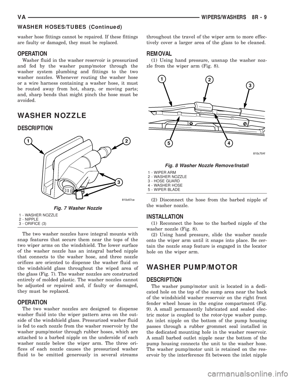
The two washer nozzles have integral mounts with
snap features that secure them near the tops of the
two wiper arms on the windshield. The lower surface
of the washer nozzle has an integral barbed nipple
that connects to the washer hose, and three nozzle
orifices are oriented to dispense the washer fluid on
the windshield glass throughout the wiped area of
the glass (Fig. 7). The washer nozzles are constructed
entirely of molded plastic. The washer nozzles cannot
be adjusted or repaired and, if faulty or damaged,
they must be replaced.
OPERATION
The two washer nozzles are designed to dispense
washer fluid into the wiper pattern area on the out-
side of the windshield glass. Pressurized washer fluid
is fed to each nozzle from the washer reservoir by the
washer pump/motor through rubber hoses, which are
attached to a barbed nipple on the underside of each
washer nozzle below the wiper arm. The three ori-
fices of each nozzle causes the pressurized washer
fluid to be emitted generously in several streamsthroughout the travel of the wiper arm to more effec-
tively cover a larger area of the glass to be cleaned.
REMOVAL
(1) Using hand pressure, unsnap the washer noz-
zle from the wiper arm (Fig. 8).
(2) Disconnect the hose from the barbed nipple of
the washer nozzle.
INSTALLATION
(1) Reconnect the hose to the barbed nipple of the
washer nozzle (Fig. 8).
(2) Using hand pressure, slide the washer nozzle
onto the wiper arm until it snaps into place. Be cer-
tain the nozzle snap feature is engaged in the locator
hole on the wiper arm.
WASHER PUMP/MOTOR
DESCRIPTION
The washer pump/motor unit is located in a dedi-
cated hole on the top of the sump area near the back
of the windshield washer reservoir on the right front
fender wheel house in the engine compartment (Fig.
9). A small permanently lubricated and sealed elec-
tric motor is coupled to the rotor-type washer pump.
An inlet nipple on the bottom of the pump housing
passes through a rubber grommet seal installed in
the dedicated mounting hole in the washer reservoir.
A small barbed outlet nipple near the bottom of the
pump housing connects the unit to the washer hose.
The washer pump/motor unit is retained on the res-
ervoir by the interference fit between the inlet nipple
Fig. 7 Washer Nozzle
1 - WASHER NOZZLE
2 - NIPPLE
3 - ORIFICE (3)
Fig. 8 Washer Nozzle Remove/Install
1 - WIPER ARM
2 - WASHER NOZZLE
3 - HOSE GUARD
4 - WASHER HOSE
5 - WIPER BLADE
VAWIPERS/WASHERS 8R - 9
WASHER HOSES/TUBES (Continued)
Page 292 of 1232
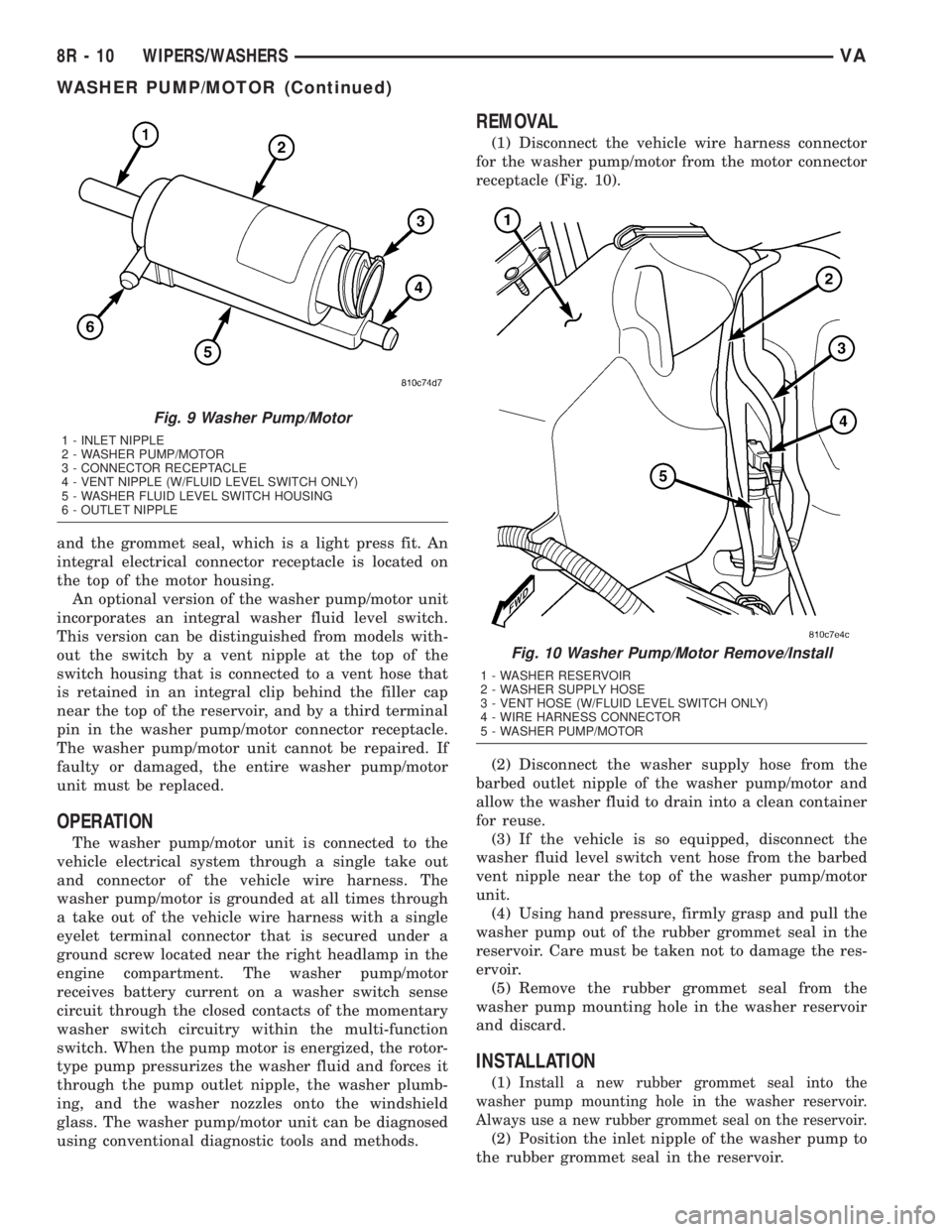
and the grommet seal, which is a light press fit. An
integral electrical connector receptacle is located on
the top of the motor housing.
An optional version of the washer pump/motor unit
incorporates an integral washer fluid level switch.
This version can be distinguished from models with-
out the switch by a vent nipple at the top of the
switch housing that is connected to a vent hose that
is retained in an integral clip behind the filler cap
near the top of the reservoir, and by a third terminal
pin in the washer pump/motor connector receptacle.
The washer pump/motor unit cannot be repaired. If
faulty or damaged, the entire washer pump/motor
unit must be replaced.
OPERATION
The washer pump/motor unit is connected to the
vehicle electrical system through a single take out
and connector of the vehicle wire harness. The
washer pump/motor is grounded at all times through
a take out of the vehicle wire harness with a single
eyelet terminal connector that is secured under a
ground screw located near the right headlamp in the
engine compartment. The washer pump/motor
receives battery current on a washer switch sense
circuit through the closed contacts of the momentary
washer switch circuitry within the multi-function
switch. When the pump motor is energized, the rotor-
type pump pressurizes the washer fluid and forces it
through the pump outlet nipple, the washer plumb-
ing, and the washer nozzles onto the windshield
glass. The washer pump/motor unit can be diagnosed
using conventional diagnostic tools and methods.
REMOVAL
(1) Disconnect the vehicle wire harness connector
for the washer pump/motor from the motor connector
receptacle (Fig. 10).
(2) Disconnect the washer supply hose from the
barbed outlet nipple of the washer pump/motor and
allow the washer fluid to drain into a clean container
for reuse.
(3) If the vehicle is so equipped, disconnect the
washer fluid level switch vent hose from the barbed
vent nipple near the top of the washer pump/motor
unit.
(4) Using hand pressure, firmly grasp and pull the
washer pump out of the rubber grommet seal in the
reservoir. Care must be taken not to damage the res-
ervoir.
(5) Remove the rubber grommet seal from the
washer pump mounting hole in the washer reservoir
and discard.
INSTALLATION
(1)Install a new rubber grommet seal into the
washer pump mounting hole in the washer reservoir.
Always use a new rubber grommet seal on the reservoir.
(2) Position the inlet nipple of the washer pump to
the rubber grommet seal in the reservoir.
Fig. 9 Washer Pump/Motor
1 - INLET NIPPLE
2 - WASHER PUMP/MOTOR
3 - CONNECTOR RECEPTACLE
4 - VENT NIPPLE (W/FLUID LEVEL SWITCH ONLY)
5 - WASHER FLUID LEVEL SWITCH HOUSING
6 - OUTLET NIPPLE
Fig. 10 Washer Pump/Motor Remove/Install
1 - WASHER RESERVOIR
2 - WASHER SUPPLY HOSE
3 - VENT HOSE (W/FLUID LEVEL SWITCH ONLY)
4 - WIRE HARNESS CONNECTOR
5 - WASHER PUMP/MOTOR
8R - 10 WIPERS/WASHERSVA
WASHER PUMP/MOTOR (Continued)
Page 813 of 1232
CATALYTIC CONVERTER
REMOVAL
(1) Raise and support the vehicle.
(2) Saturate the clamp nuts with heat valve lubri-
cant. Allow 5 minutes for penetration. Remove the
rear clamp. (Fig. 1)
(3) Saturate the clamp nuts with heat valve lubri-
cant. Allow 5 minutes for penetration. Remove the
front clamp.
(4) Remove the cataylic converter and muffler
assembly from the isolators.
(5) Seperat the cataylic converter and muffler
assembly from the tailpipe and the exhaust pipe.
(6) Remove the cataylic converter and muffler
assembly and isolators from the vehicle.
(7) Remove the bolt, nut and front isolator from
the cataylic converter and muffler assembly.
(8) Remove the rear isolator from the cataylic con-
verter and muffler assembly.
(9)
INSTALLATION
(1) Install bolt, front isolator and nut (Fig. 1).
(2) Install rear insulator onto the cataylic con-
verter and muffler assembly
(3) Position the cataylic conveter and muffler
assembly into the exhaust pipe and tailpipe until
alignment tab is inserted into the alignment slot.
(4) Install the front and rear insulators.
(5) Install the real clamp.
(6) Install the front clamp.
(7) Lower vehicle.
(8) Start the vehicle and inspect for exhaust leaks.
Repair exhaust leaks as necessary.
(9) Check the exhaust system for contact with the
body panels. Make necessary adjustments, if neces-
sary.
EXHAUST PIPE
REMOVAL
(1) Raise and support the vehicle.
(2) Saturate the clamp nuts with heat valve lubri-
cant. Allow 5 minutes for penetration. Remove the
front and rear clamp (Fig. 1).
(3) Remove the mounting bracket nuts.
(4) Remove the exhaust pipe.
INSTALLATION
(1) Position the exhaust pipe into the exhaust pipe
into the cataylic converter and muffler assembly
until alignment tab is inserted into the alignment
slot.
(2) Install mounting bracket and nuts (Fig. 1).(3) Install clamp.
(4) Lower the vehicle.
(5) Start the vehicle and inspect for exhaust leaks.
Repair exhaust leaks as necessary.
(6) Check the exhaust system for contact with the
body panels. Make necessary adjustments, if neces-
sary.
TAILPIPE
REMOVAL
(1) Raise and support the vehicle.
(2) Saturate the clamp nuts with heat valve lubri-
cant. Allow 5 minutes for penetration (Fig. 1).
(3) Remove the clamp.
(4) Remove the tailpipe and insulator form the
vehicle
(5) Remove the insulator from the tailpipe.
INSTALLATION
(1) Position the tail pipe into the cataylic converter
and muffler assembly until alignment tab is inserted
into the alignment slot.
(2) Install the insulator.
(3) Install the clamp.
(4) Lower the vehicle.
(5) Start the vehicle and inspect for exhaust leaks.
Repair exhaust leaks as necessary.
(6) Check the exhaust system for contact with the
body panels. Make necessary adjustments, if neces-
sary.
TURBOCHARGER SYSTEM
DESCRIPTION
CAUTION: The turbocharger is a performance part
and must not be tampered with. The boost pressure
bracket is an integral part of the turbocharger. Tam-
pering with the boost pressure components can
reduce durability by increasing cylinder pressure
and thermal loading due to incorrect inlet and
exhaust manifold pressure. Poor fuel economy and
failure to meet regulatory emissions laws may
result. Increasing the turbocharger boost WILL NOT
increase engine power.
The turbocharger used on this vehicle is of the
variable turbine type. These turbochargers use the
entire exhaust energy to boost efficiency of the turbo-
charger and the engine.
The advantages of a turbocharger with variable
turbine geometry are:
²Higher charge pressure already in the lower and
in upper engine speed ranges.
VAEXHAUST SYSTEM 11 - 3
Page 862 of 1232
DIAGNOSIS AND TESTING - POWER STEERING SYSTEM
There is some noise in all power steering systems. One of the most common is a hissing sound evident at a
standstill parking. Or when the steering wheel is at the end of it's travel. Hiss is a high frequency noise similar
to that of a water tap being closed slowly. The noise is present in all valves that have a high velocity fluid passing
through an orifice. There is no relationship between this noise and steering performance.
STEERING NOISE
CONDITION POSSIBLE CAUSES CORRECTION
OBJECTIONAL HISS OR
WHISTLE1. Steering intermediate shaft to dash panel
seal.1. Check and repair seal at dash
panel.
2. Noisy valve in power steering gear. 2. Replace steering gear.
RATTLE OR CLUNK 1. Gear mounting bolts loose. 1. Tighten bolts to specification.
2. Loose or damaged suspension
components.2. Inspect and repair suspension.
3. Internal gear noise. 3. Replace steering gear.
4. Pressure hose in contact with other
components.4. Reposition hose.
5. Loose or damaged intermediate shaft or
column.5. Inspect and repair or replace.
CHIRP OR SQUEAL 1. Loose belt. 1. Adjust or replace.
WHINE OR GROWL 1. Low fluid level. 1. Fill to proper level.
2. Pressure hose in contact with other
components.2. Reposition hose.
3. Internal pump noise. 3. Replace pump.
4. Air in fluid 4. Check for lekas, Evacuate air
from P/S system.
SUCKING AIR SOUND 1. Loose return line clamp. 1. Replace clamp.
2. O-ring missing or damaged on hose
fitting.2. Replace o-ring.
3. Low fluid level. 3. Fill to proper level.
4. Air leak between pump and reservoir. 4. Repair as necessary.
5. Reservoir cap not installed correctly. 5. Install reservoir cap correctly.
SCRUBBING OR
KNOCKING1. Wrong tire size. 1. Verify tire size.
19 - 2 STEERINGVA
STEERING (Continued)
Page 863 of 1232
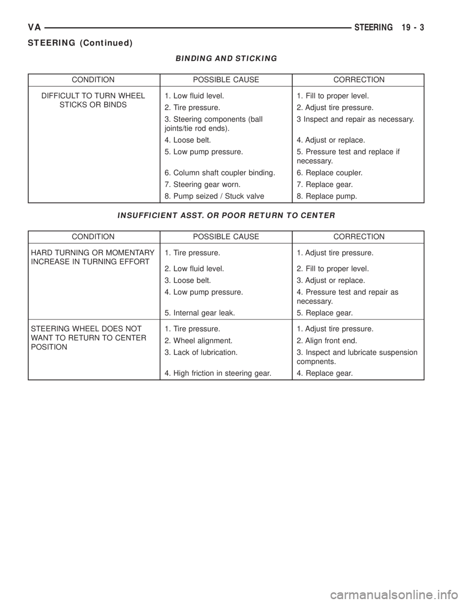
BINDING AND STICKING
CONDITION POSSIBLE CAUSE CORRECTION
DIFFICULT TO TURN WHEEL
STICKS OR BINDS1. Low fluid level. 1. Fill to proper level.
2. Tire pressure. 2. Adjust tire pressure.
3. Steering components (ball
joints/tie rod ends).3 Inspect and repair as necessary.
4. Loose belt. 4. Adjust or replace.
5. Low pump pressure. 5. Pressure test and replace if
necessary.
6. Column shaft coupler binding. 6. Replace coupler.
7. Steering gear worn. 7. Replace gear.
8. Pump seized / Stuck valve 8. Replace pump.
INSUFFICIENT ASST. OR POOR RETURN TO CENTER
CONDITION POSSIBLE CAUSE CORRECTION
HARD TURNING OR MOMENTARY
INCREASE IN TURNING EFFORT1. Tire pressure. 1. Adjust tire pressure.
2. Low fluid level. 2. Fill to proper level.
3. Loose belt. 3. Adjust or replace.
4. Low pump pressure. 4. Pressure test and repair as
necessary.
5. Internal gear leak. 5. Replace gear.
STEERING WHEEL DOES NOT
WANT TO RETURN TO CENTER
POSITION1. Tire pressure. 1. Adjust tire pressure.
2. Wheel alignment. 2. Align front end.
3. Lack of lubrication. 3. Inspect and lubricate suspension
compnents.
4. High friction in steering gear. 4. Replace gear.
VASTEERING 19 - 3
STEERING (Continued)
Page 864 of 1232
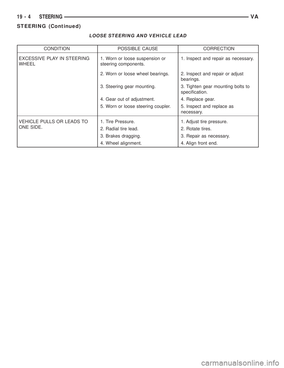
LOOSE STEERING AND VEHICLE LEAD
CONDITION POSSIBLE CAUSE CORRECTION
EXCESSIVE PLAY IN STEERING
WHEEL1. Worn or loose suspension or
steering components.1. Inspect and repair as necessary.
2. Worn or loose wheel bearings. 2. Inspect and repair or adjust
bearings.
3. Steering gear mounting. 3. Tighten gear mounting bolts to
specification.
4. Gear out of adjustment. 4. Replace gear.
5. Worn or loose steering coupler. 5. Inspect and replace as
necessary.
VEHICLE PULLS OR LEADS TO
ONE SIDE.1. Tire Pressure. 1. Adjust tire pressure.
2. Radial tire lead. 2. Rotate tires.
3. Brakes dragging. 3. Repair as necessary.
4. Wheel alignment. 4. Align front end.
19 - 4 STEERINGVA
STEERING (Continued)
Page 958 of 1232
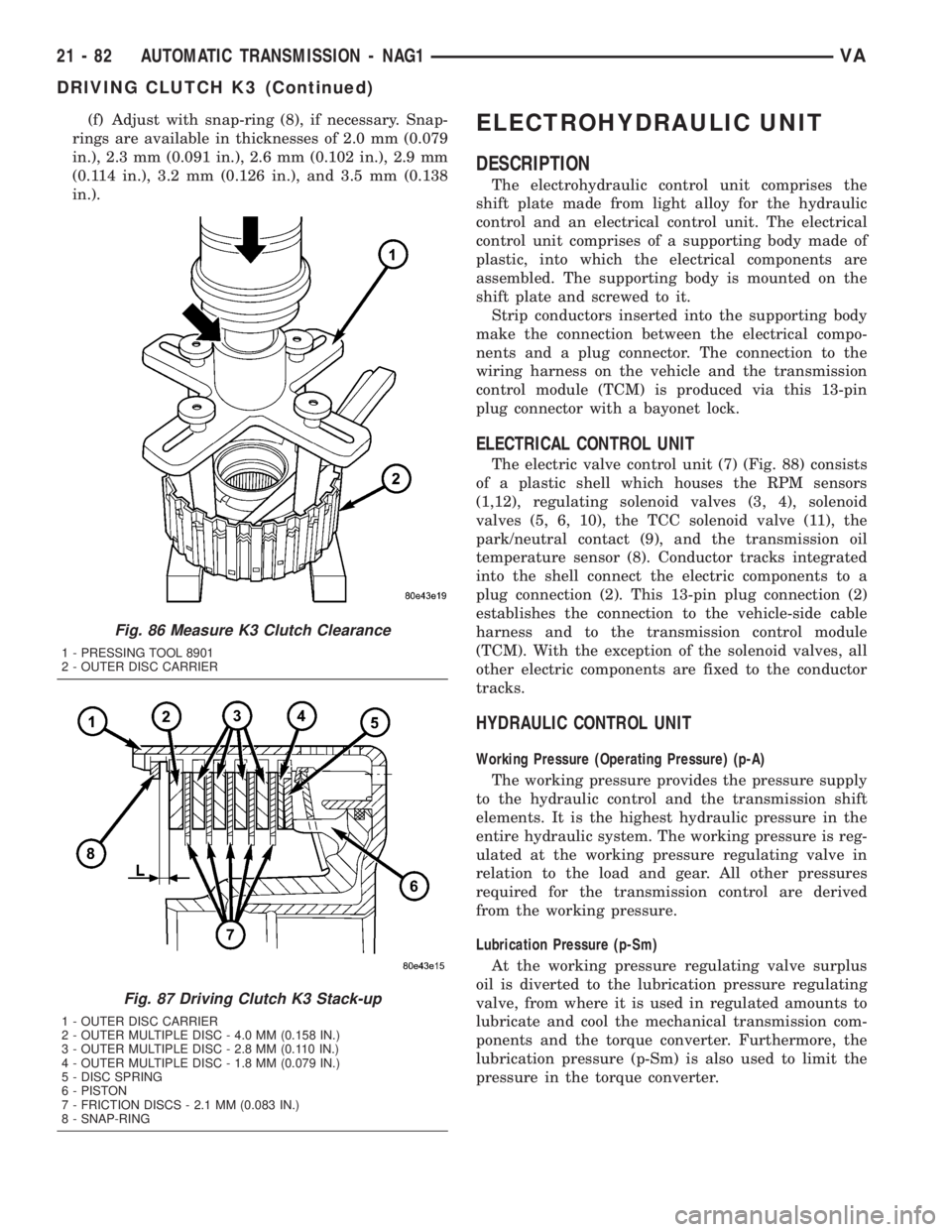
(f) Adjust with snap-ring (8), if necessary. Snap-
rings are available in thicknesses of 2.0 mm (0.079
in.), 2.3 mm (0.091 in.), 2.6 mm (0.102 in.), 2.9 mm
(0.114 in.), 3.2 mm (0.126 in.), and 3.5 mm (0.138
in.).ELECTROHYDRAULIC UNIT
DESCRIPTION
The electrohydraulic control unit comprises the
shift plate made from light alloy for the hydraulic
control and an electrical control unit. The electrical
control unit comprises of a supporting body made of
plastic, into which the electrical components are
assembled. The supporting body is mounted on the
shift plate and screwed to it.
Strip conductors inserted into the supporting body
make the connection between the electrical compo-
nents and a plug connector. The connection to the
wiring harness on the vehicle and the transmission
control module (TCM) is produced via this 13-pin
plug connector with a bayonet lock.
ELECTRICAL CONTROL UNIT
The electric valve control unit (7) (Fig. 88) consists
of a plastic shell which houses the RPM sensors
(1,12), regulating solenoid valves (3, 4), solenoid
valves (5, 6, 10), the TCC solenoid valve (11), the
park/neutral contact (9), and the transmission oil
temperature sensor (8). Conductor tracks integrated
into the shell connect the electric components to a
plug connection (2). This 13-pin plug connection (2)
establishes the connection to the vehicle-side cable
harness and to the transmission control module
(TCM). With the exception of the solenoid valves, all
other electric components are fixed to the conductor
tracks.
HYDRAULIC CONTROL UNIT
Working Pressure (Operating Pressure) (p-A)
The working pressure provides the pressure supply
to the hydraulic control and the transmission shift
elements. It is the highest hydraulic pressure in the
entire hydraulic system. The working pressure is reg-
ulated at the working pressure regulating valve in
relation to the load and gear. All other pressures
required for the transmission control are derived
from the working pressure.
Lubrication Pressure (p-Sm)
At the working pressure regulating valve surplus
oil is diverted to the lubrication pressure regulating
valve, from where it is used in regulated amounts to
lubricate and cool the mechanical transmission com-
ponents and the torque converter. Furthermore, the
lubrication pressure (p-Sm) is also used to limit the
pressure in the torque converter.
Fig. 86 Measure K3 Clutch Clearance
1 - PRESSING TOOL 8901
2 - OUTER DISC CARRIER
Fig. 87 Driving Clutch K3 Stack-up
1 - OUTER DISC CARRIER
2 - OUTER MULTIPLE DISC - 4.0 MM (0.158 IN.)
3 - OUTER MULTIPLE DISC - 2.8 MM (0.110 IN.)
4 - OUTER MULTIPLE DISC - 1.8 MM (0.079 IN.)
5 - DISC SPRING
6 - PISTON
7 - FRICTION DISCS - 2.1 MM (0.083 IN.)
8 - SNAP-RING
21 - 82 AUTOMATIC TRANSMISSION - NAG1VA
DRIVING CLUTCH K3 (Continued)
Page 1025 of 1232
TIRES/WHEELS
TABLE OF CONTENTS
page page
TIRES/WHEELS
DIAGNOSIS AND TESTING - TIRE AND
WHEEL RUNOUT......................1
STANDARD PROCEDURE
STANDARD PROCEDURE - MATCH
MOUNTING...........................2
STANDARD PROCEDURE - TIRE AND
WHEEL BALANCE......................3
STANDARD PROCEDURE - TIRE ROTATION . 5
SPECIFICATIONS
TORQUE CHART......................5
TIRES
DESCRIPTION
DESCRIPTION - TIRES..................6
DESCRIPTION - RADIAL ± PLY TIRES......6
DESCRIPTION - TIRE PRESSURE FOR
HIGH SPEEDS.........................6
DESCRIPTION - REPLACEMENT TIRES.....7
DESCRIPTION - TIRE INFLATION
PRESSURES..........................7
DIAGNOSIS AND TESTING
DIAGNOSIS AND TESTING - PRESSURE
GAUGES.............................8
DIAGNOSIS AND TESTING - TIRE NOISE
OR VIBRATION........................8
DIAGNOSIS AND TESTING - TREAD WEAR
INDICATORS..........................8DIAGNOSIS AND TESTING - TIRE WEAR
PATTERNS...........................8
DIAGNOSIS AND TESTING - TIRE/VEHICLE
LEAD................................8
STANDARD PROCEDURE - REPAIRING
LEAKS..............................10
CLEANING............................10
SPECIFICATIONS
TIRES..............................10
SPARE TIRE CARRIER
REMOVAL.............................10
INSTALLATION.........................10
WHEELS
DESCRIPTION.........................11
OPERATION...........................11
DIAGNOSIS AND TESTING
WHEEL INSPECTION..................11
STANDARD PROCEDURE
STANDARD PROCEDURE - WHEEL
REPLACEMENT.......................11
STANDARD PROCEDURE - DUAL REAR
WHEEL INSTALLATION.................12
REMOVAL.............................13
INSTALLATION.........................13
TIRES/WHEELS
DIAGNOSIS AND TESTING - TIRE AND WHEEL
RUNOUT
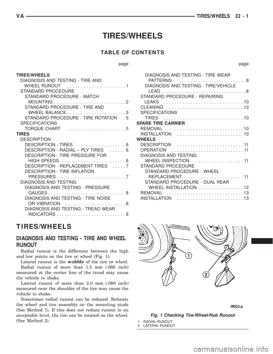
Radial runout is the difference between the high
and low points on the tire or wheel (Fig. 1).
Lateral runout is thewobbleof the tire or wheel.
Radial runout of more than 1.5 mm (.060 inch)
measured at the center line of the tread may cause
the vehicle to shake.
Lateral runout of more than 2.0 mm (.080 inch)
measured near the shoulder of the tire may cause the
vehicle to shake.
Sometimes radial runout can be reduced. Relocate
the wheel and tire assembly on the mounting studs
(See Method 1). If this does not reduce runout to an
acceptable level, the tire can be rotated on the wheel.
(See Method 2).
Fig. 1 Checking Tire/Wheel/Hub Runout
1 - RADIAL RUNOUT
2 - LATERAL RUNOUT
VATIRES/WHEELS 22 - 1