2005 MERCEDES-BENZ SPRINTER recommended oil
[x] Cancel search: recommended oilPage 785 of 1232
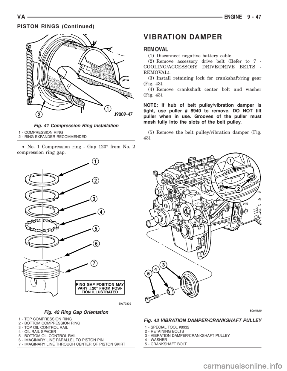
²No. 1 Compression ring - Gap 120É from No. 2
compression ring gap.
VIBRATION DAMPER
REMOVAL
(1) Disconnect negative battery cable.
(2) Remove accessory drive belt (Refer to 7 -
COOLING/ACCESSORY DRIVE/DRIVE BELTS -
REMOVAL).
(3) Install retaining lock for crankshaft/ring gear
(Fig. 43).
(4) Remove crankshaft center bolt and washer
(Fig. 43).
NOTE: If hub of belt pulley/vibration damper is
tight, use puller # 8940 to remove. DO NOT tilt
puller when in use. Grooves of the puller must
mesh fully into the slots of the belt pulley.
(5) Remove the belt pulley/vibration damper (Fig.
43).
Fig. 41 Compression Ring Installation
1 - COMPRESSION RING
2 - RING EXPANDER RECOMMENDED
Fig. 42 Ring Gap Orientation
1 - TOP COMPRESSION RING
2 - BOTTOM COMPRESSION RING
3 - TOP OIL CONTROL RAIL
4 - OIL RAIL SPACER
5 - BOTTOM OIL CONTROL RAIL
6 - IMAGINARY LINE PARALLEL TO PISTON PIN
7 - IMAGINARY LINE THROUGH CENTER OF PISTON SKIRTFig. 43 VIBRATION DAMPER/CRANKSHAFT PULLEY
1 - SPECIAL TOOL #8932
2 - RETAINING BOLTS
3 - VIBRATION DAMPER/CRANKSHAFT PULLEY
4 - WASHER
5 - CRANKSHAFT BOLT
VAENGINE 9 - 47
PISTON RINGS (Continued)
Page 833 of 1232
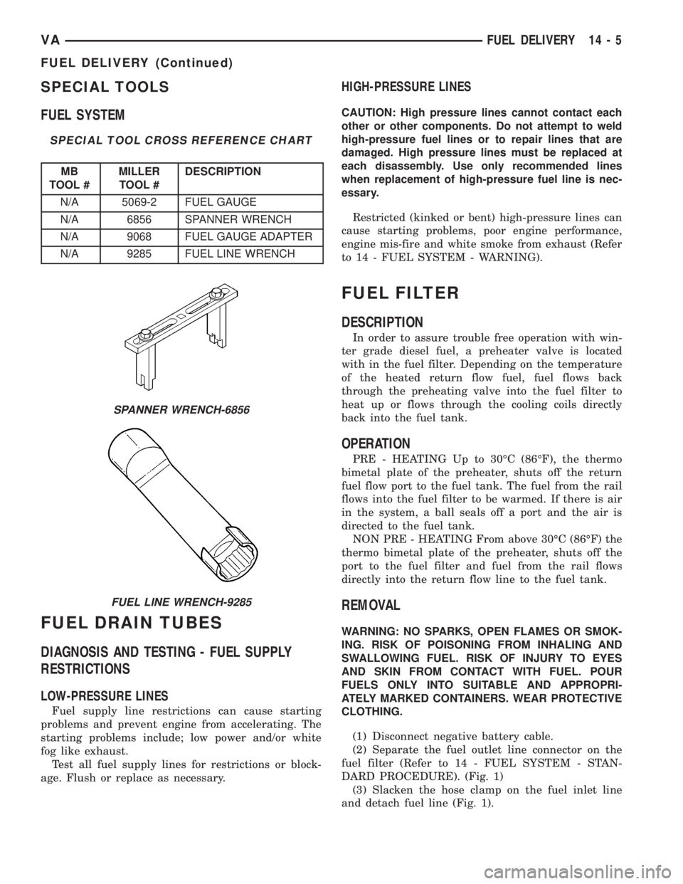
SPECIAL TOOLS
FUEL SYSTEM
SPECIAL TOOL CROSS REFERENCE CHART
MB
TOOL #MILLER
TOOL #DESCRIPTION
N/A 5069-2 FUEL GAUGE
N/A 6856 SPANNER WRENCH
N/A 9068 FUEL GAUGE ADAPTER
N/A 9285 FUEL LINE WRENCH
FUEL DRAIN TUBES
DIAGNOSIS AND TESTING - FUEL SUPPLY
RESTRICTIONS
LOW-PRESSURE LINES
Fuel supply line restrictions can cause starting
problems and prevent engine from accelerating. The
starting problems include; low power and/or white
fog like exhaust.
Test all fuel supply lines for restrictions or block-
age. Flush or replace as necessary.
HIGH-PRESSURE LINES
CAUTION: High pressure lines cannot contact each
other or other components. Do not attempt to weld
high-pressure fuel lines or to repair lines that are
damaged. High pressure lines must be replaced at
each disassembly. Use only recommended lines
when replacement of high-pressure fuel line is nec-
essary.
Restricted (kinked or bent) high-pressure lines can
cause starting problems, poor engine performance,
engine mis-fire and white smoke from exhaust (Refer
to 14 - FUEL SYSTEM - WARNING).
FUEL FILTER
DESCRIPTION
In order to assure trouble free operation with win-
ter grade diesel fuel, a preheater valve is located
with in the fuel filter. Depending on the temperature
of the heated return flow fuel, fuel flows back
through the preheating valve into the fuel filter to
heat up or flows through the cooling coils directly
back into the fuel tank.
OPERATION
PRE - HEATING Up to 30ÉC (86ÉF), the thermo
bimetal plate of the preheater, shuts off the return
fuel flow port to the fuel tank. The fuel from the rail
flows into the fuel filter to be warmed. If there is air
in the system, a ball seals off a port and the air is
directed to the fuel tank.
NON PRE - HEATING From above 30ÉC (86ÉF) the
thermo bimetal plate of the preheater, shuts off the
port to the fuel filter and fuel from the rail flows
directly into the return flow line to the fuel tank.
REMOVAL
WARNING: NO SPARKS, OPEN FLAMES OR SMOK-
ING. RISK OF POISONING FROM INHALING AND
SWALLOWING FUEL. RISK OF INJURY TO EYES
AND SKIN FROM CONTACT WITH FUEL. POUR
FUELS ONLY INTO SUITABLE AND APPROPRI-
ATELY MARKED CONTAINERS. WEAR PROTECTIVE
CLOTHING.
(1) Disconnect negative battery cable.
(2) Separate the fuel outlet line connector on the
fuel filter (Refer to 14 - FUEL SYSTEM - STAN-
DARD PROCEDURE). (Fig. 1)
(3) Slacken the hose clamp on the fuel inlet line
and detach fuel line (Fig. 1).
SPANNER WRENCH-6856
FUEL LINE WRENCH-9285
VAFUEL DELIVERY 14 - 5
FUEL DELIVERY (Continued)
Page 978 of 1232
DIAGNOSIS AND TESTING
DIAGNOSIS AND TESTING - EFFECTS OF
INCORRECT FLUID LEVEL
A low fluid level allows the pump to take in air
along with the fluid. Air in the fluid will cause fluid
pressures to be low and develop slower than normal.
If the transmission is overfilled, the gears churn the
fluid into foam. This aerates the fluid and causing
the same conditions occurring with a low level. In
either case, air bubbles cause fluid overheating, oxi-
dation and varnish buildup which interferes with
valve and clutch operation. Foaming also causes fluid
expansion which can result in fluid overflow from the
transmission vent or fill tube. Fluid overflow can eas-
ily be mistaken for a leak if inspection is not careful.
DIAGNOSIS AND TESTING - CAUSES OF
BURNT FLUID
Burnt, discolored fluid is a result of overheating
which has three primary causes.
(1) Internal clutch slippage, usually caused by low
line pressure, inadequate clutch apply pressure, or
clutch seal failure.
(2) A result of restricted fluid flow through the
main and/or auxiliary cooler. This condition is usu-
ally the result of a faulty or improperly installed
drainback valve, a damaged main cooler, or severe
restrictions in the coolers and lines caused by debris
or kinked lines.
(3) Heavy duty operation with a vehicle not prop-
erly equipped for this type of operation. Trailer tow-
ing or similar high load operation will overheat the
transmission fluid if the vehicle is improperly
equipped. Such vehicles should have an auxiliary
transmission fluid cooler, a heavy duty cooling sys-
tem, and the engine/axle ratio combination needed to
handle heavy loads.
DIAGNOSIS AND TESTING - FLUID
CONTAMINATION
Transmission fluid contamination is generally a
result of:
²adding incorrect fluid
²failure to clean dipstick and fill tube when
checking level
²engine coolant entering the fluid
²internal failure that generates debris
²overheat that generates sludge (fluid break-
down)
²failure to replace contaminated converter after
repair
The use of non-recommended fluids can result in
transmission failure. The usual results are erratic
shifts, slippage, abnormal wear and eventual failuredue to fluid breakdown and sludge formation. Avoid
this condition by using recommended fluids only.
The dipstick cap and fill tube should be wiped
clean before checking fluid level. Dirt, grease and
other foreign material on the cap and tube could fall
into the tube if not removed beforehand. Take the
time to wipe the cap and tube clean before withdraw-
ing the dipstick.
Engine coolant in the transmission fluid is gener-
ally caused by a cooler malfunction. The only remedy
is to replace the radiator as the cooler in the radiator
is not a serviceable part. If coolant has circulated
through the transmission, an overhaul is necessary.
The torque converter should be replaced whenever
a failure generates sludge and debris. This is neces-
sary because normal converter flushing procedures
will not remove all contaminants.
STANDARD PROCEDURE
STANDARD PROCEDURE - CHECK OIL LEVEL
(1) Verify that the vehicle is parked on a level sur-
face.
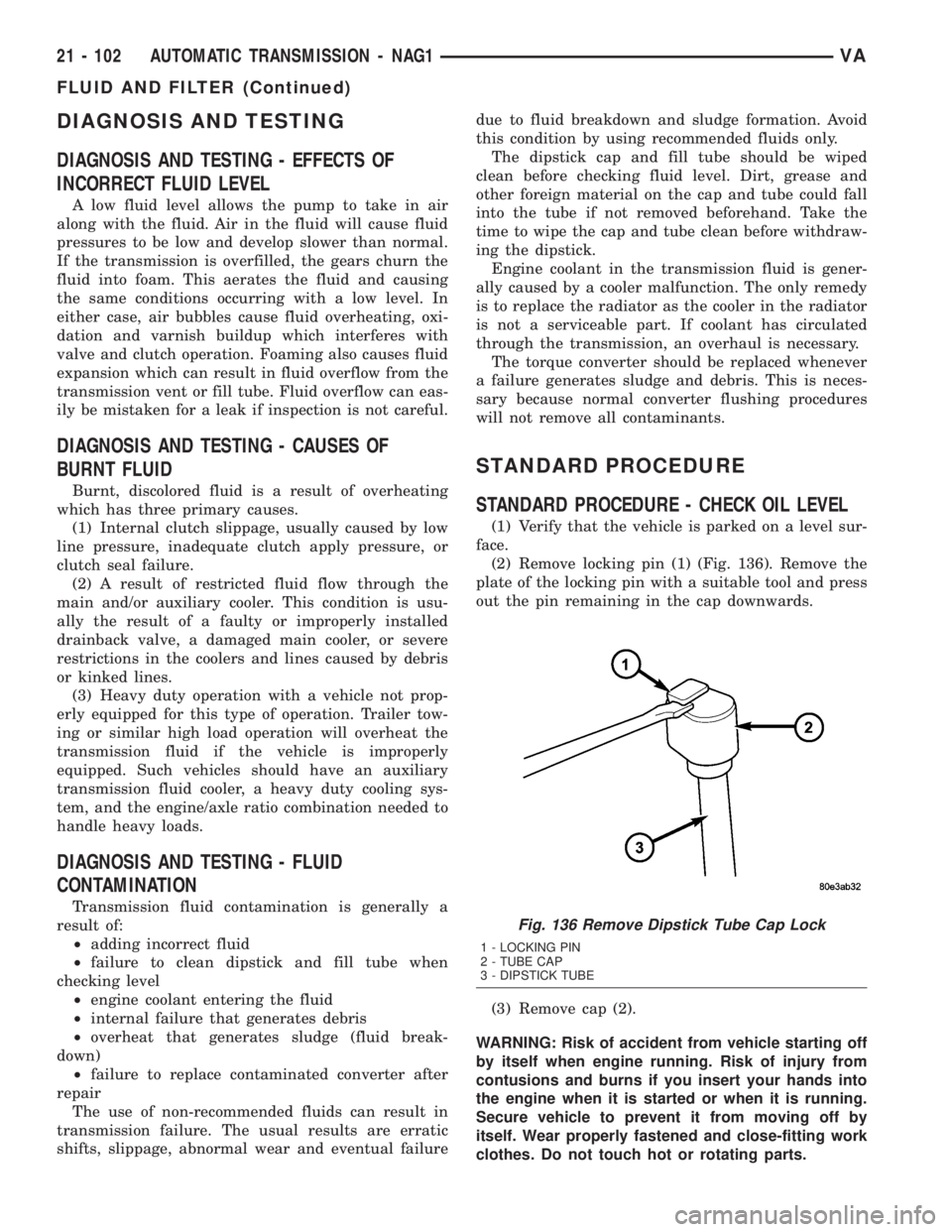
(2) Remove locking pin (1) (Fig. 136). Remove the
plate of the locking pin with a suitable tool and press
out the pin remaining in the cap downwards.
(3) Remove cap (2).
WARNING: Risk of accident from vehicle starting off
by itself when engine running. Risk of injury from
contusions and burns if you insert your hands into
the engine when it is started or when it is running.
Secure vehicle to prevent it from moving off by
itself. Wear properly fastened and close-fitting work
clothes. Do not touch hot or rotating parts.
Fig. 136 Remove Dipstick Tube Cap Lock
1 - LOCKING PIN
2 - TUBE CAP
3 - DIPSTICK TUBE
21 - 102 AUTOMATIC TRANSMISSION - NAG1VA
FLUID AND FILTER (Continued)
Page 1023 of 1232
(2) Place torque converter in position on transmis-
sion.
CAUTION: Do not damage oil pump seal or con-
verter hub while inserting torque converter into the
front of the transmission.
(3) Align torque converter to oil pump seal open-
ing.
(4) Insert torque converter hub into oil pump.
(5) While pushing torque converter inward, rotate
converter until converter is fully seated in the oil
pump gears.
(6) Check converter seating with a scale and
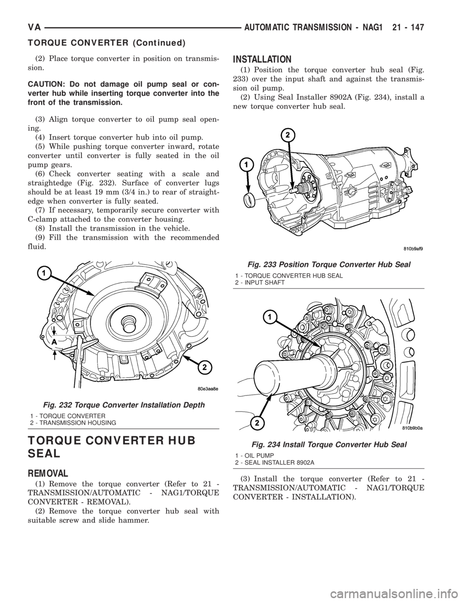
straightedge (Fig. 232). Surface of converter lugs
should be at least 19 mm (3/4 in.) to rear of straight-
edge when converter is fully seated.
(7) If necessary, temporarily secure converter with
C-clamp attached to the converter housing.
(8) Install the transmission in the vehicle.
(9) Fill the transmission with the recommended
fluid.
TORQUE CONVERTER HUB
SEAL
REMOVAL
(1) Remove the torque converter (Refer to 21 -
TRANSMISSION/AUTOMATIC - NAG1/TORQUE
CONVERTER - REMOVAL).
(2) Remove the torque converter hub seal with
suitable screw and slide hammer.
INSTALLATION
(1) Position the torque converter hub seal (Fig.
233) over the input shaft and against the transmis-
sion oil pump.
(2) Using Seal Installer 8902A (Fig. 234), install a
new torque converter hub seal.
(3) Install the torque converter (Refer to 21 -
TRANSMISSION/AUTOMATIC - NAG1/TORQUE
CONVERTER - INSTALLATION).
Fig. 232 Torque Converter Installation Depth
1 - TORQUE CONVERTER
2 - TRANSMISSION HOUSING
Fig. 233 Position Torque Converter Hub Seal
1 - TORQUE CONVERTER HUB SEAL
2 - INPUT SHAFT
Fig. 234 Install Torque Converter Hub Seal
1 - OIL PUMP
2 - SEAL INSTALLER 8902A
VAAUTOMATIC TRANSMISSION - NAG1 21 - 147
TORQUE CONVERTER (Continued)
Page 1035 of 1232
WHEELS
DESCRIPTION
Original equipment wheels are designed for the
specified Maximum Vehicle Capacity.
All models use steel or aluminum wheels.
Aluminum wheels require special balance weights
and alignment equipment.
(1) On vehicles equipped with dual rear wheels,
The slots in the wheel must be aligned to provide
access to the valve stem.
OPERATION
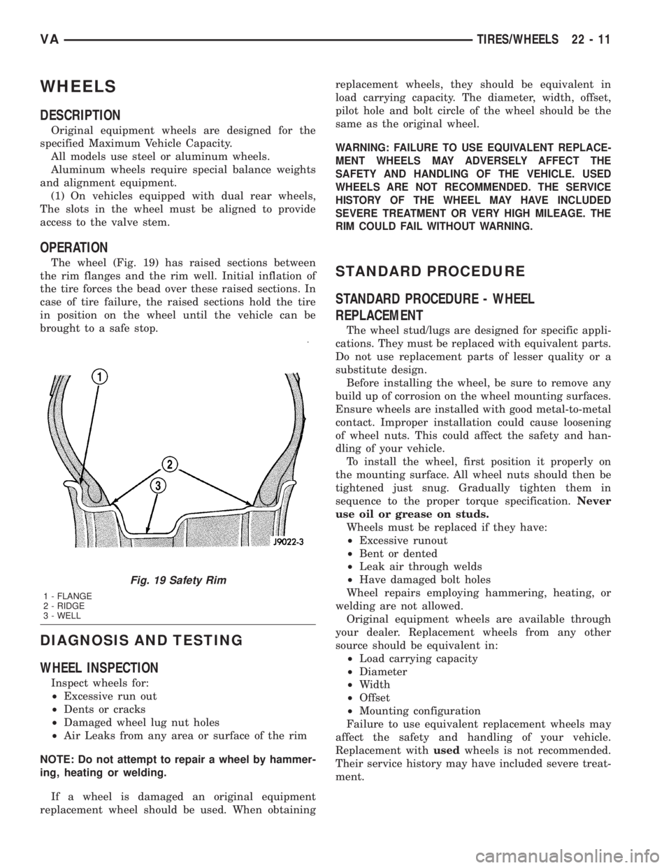
The wheel (Fig. 19) has raised sections between
the rim flanges and the rim well. Initial inflation of
the tire forces the bead over these raised sections. In
case of tire failure, the raised sections hold the tire
in position on the wheel until the vehicle can be
brought to a safe stop.
DIAGNOSIS AND TESTING
WHEEL INSPECTION
Inspect wheels for:
²Excessive run out
²Dents or cracks
²Damaged wheel lug nut holes
²Air Leaks from any area or surface of the rim
NOTE: Do not attempt to repair a wheel by hammer-
ing, heating or welding.
If a wheel is damaged an original equipment
replacement wheel should be used. When obtainingreplacement wheels, they should be equivalent in
load carrying capacity. The diameter, width, offset,
pilot hole and bolt circle of the wheel should be the
same as the original wheel.
WARNING: FAILURE TO USE EQUIVALENT REPLACE-
MENT WHEELS MAY ADVERSELY AFFECT THE
SAFETY AND HANDLING OF THE VEHICLE. USED
WHEELS ARE NOT RECOMMENDED. THE SERVICE
HISTORY OF THE WHEEL MAY HAVE INCLUDED
SEVERE TREATMENT OR VERY HIGH MILEAGE. THE
RIM COULD FAIL WITHOUT WARNING.
STANDARD PROCEDURE
STANDARD PROCEDURE - WHEEL
REPLACEMENT
The wheel stud/lugs are designed for specific appli-
cations. They must be replaced with equivalent parts.
Do not use replacement parts of lesser quality or a
substitute design.
Before installing the wheel, be sure to remove any
build up of corrosion on the wheel mounting surfaces.
Ensure wheels are installed with good metal-to-metal
contact. Improper installation could cause loosening
of wheel nuts. This could affect the safety and han-
dling of your vehicle.
To install the wheel, first position it properly on
the mounting surface. All wheel nuts should then be
tightened just snug. Gradually tighten them in
sequence to the proper torque specification.Never
use oil or grease on studs.
Wheels must be replaced if they have:
²Excessive runout
²Bent or dented
²Leak air through welds
²Have damaged bolt holes
Wheel repairs employing hammering, heating, or
welding are not allowed.
Original equipment wheels are available through
your dealer. Replacement wheels from any other
source should be equivalent in:
²Load carrying capacity
²Diameter
²Width
²Offset
²Mounting configuration
Failure to use equivalent replacement wheels may
affect the safety and handling of your vehicle.
Replacement withusedwheels is not recommended.
Their service history may have included severe treat-
ment.
Fig. 19 Safety Rim
1 - FLANGE
2 - RIDGE
3 - WELL
VATIRES/WHEELS 22 - 11
Page 1172 of 1232
PLUMBING
DESCRIPTION - REFRIGERANT LINE
The refrigerant lines and hoses are used to carry
the refrigerant between the various air conditioning
system components. A barrier hose design with a
nylon tube, which is sandwiched between rubber lay-
ers, is used for the R-134a air conditioning system on
this vehicle. This nylon tube helps to further contain
the R-134a refrigerant, which has a smaller molecu-
lar structure than R-12 refrigerant. The ends of the
refrigerant hoses are made from lightweight alumi-
num or steel, and commonly use braze-less fittings.
Any kinks or sharp bends in the refrigerant plumb-
ing will reduce the capacity of the entire air condi-
tioning system. Kinks and sharp bends reduce the
flow of refrigerant in the system. A good rule for the
flexible hose refrigerant lines is to keep the radius of
all bends at least ten times the diameter of the hose.
In addition, the flexible hose refrigerant lines should
be routed so they are at least 80 millimeters (3
inches) from the exhaust manifold.
OPERATION - REFRIGERANT LINE
High pressures are produced in the refrigerant sys-
tem when the air conditioning compressor is operat-
ing. Extreme care must be exercised to make sure
that each of the refrigerant system connections is
pressure-tight and leak free. It is a good practice to
inspect all flexible hose refrigerant lines at least once
a year to make sure they are in good condition and
properly routed.
The refrigerant lines and hoses cannot be repaired
and, if faulty or damaged, they must be replaced.
WARNING
WARNING: THE AIR CONDITIONING SYSTEM CON-
TAINS REFRIGERANT UNDER HIGH PRESSURE.
SEVERE PERSONAL INJURY MAY RESULT FROM
IMPROPER SERVICE PROCEDURES. REPAIRS
SHOULD ONLY BE PERFORMED BY QUALIFIED
SERVICE PERSONNEL.AVOID BREATHING THE REFRIGERANT AND
REFRIGERANT OIL VAPOR OR MIST. EXPOSURE
MAY IRRITATE THE EYES, NOSE, AND/OR THROAT.
WEAR EYE PROTECTION WHEN SERVICING THE
AIR CONDITIONING REFRIGERANT SYSTEM. SERI-
OUS EYE INJURY CAN RESULT FROM DIRECT
CONTACT WITH THE REFRIGERANT. IF EYE CON-
TACT OCCURS, SEEK MEDICAL ATTENTION IMME-
DIATELY.
DO NOT EXPOSE THE REFRIGERANT TO OPEN
FLAME. POISONOUS GAS IS CREATED WHEN
REFRIGERANT IS BURNED. AN ELECTRONIC LEAK
DETECTOR IS RECOMMENDED.
IF ACCIDENTAL SYSTEM DISCHARGE OCCURS,
VENTILATE THE WORK AREA BEFORE RESUMING
SERVICE. LARGE AMOUNTS OF REFRIGERANT
RELEASED IN A CLOSED WORK AREA WILL DIS-
PLACE THE OXYGEN AND CAUSE SUFFOCATION.
THE EVAPORATION RATE OF R-134a REFRIGER-
ANT AT AVERAGE TEMPERATURE AND ALTITUDE
IS EXTREMELY HIGH. AS A RESULT, ANYTHING
THAT COMES IN CONTACT WITH THE REFRIGER-
ANT WILL FREEZE. ALWAYS PROTECT THE SKIN
OR DELICATE OBJECTS FROM DIRECT CONTACT
WITH THE REFRIGERANT.
THE R-134a SERVICE EQUIPMENT OR THE VEHI-
CLE REFRIGERANT SYSTEM SHOULD NOT BE
PRESSURE TESTED OR LEAK TESTED WITH COM-
PRESSED AIR. SOME MIXTURES OF AIR AND
R-134a HAVE BEEN SHOWN TO BE COMBUSTIBLE
AT ELEVATED PRESSURES. THESE MIXTURES ARE
POTENTIALLY DANGEROUS, AND MAY RESULT IN
FIRE OR EXPLOSION CAUSING INJURY OR PROP-
ERTY DAMAGE.
24 - 44 PLUMBINGVA
Page 1174 of 1232
When it is necessary to open the refrigerant sys-
tem, have everything needed to service the system
ready. The refrigerant system should not be left open
to the atmosphere any longer than necessary. Cap or
plug all lines and fittings as soon as they are opened
to prevent the entrance of dirt and moisture. All lines
and components in parts stock should be capped or
sealed until they are to be installed.
All tools, including the refrigerant recycling equip-
ment, the manifold gauge set, and test hoses should
be kept clean and dry. All tools and equipment must
be designed for R-134a refrigerant.
DIAGNOSIS AND TESTING - REFRIGERANT
SYSTEM LEAKS
WARNING: REVIEW THE WARNINGS AND CAU-
TIONS IN THE FRONT OF THIS SECTION BEFORE
PERFORMING THE FOLLOWING OPERATION.
(Refer to 24 - HEATING & AIR CONDITIONING/
PLUMBING - WARNING) (Refer to 24 - HEATING &
AIR CONDITIONING/PLUMBING - CAUTION)
If the air conditioning system is not cooling prop-
erly, determine if the refrigerant system is fully-
charged. (Refer to 24 - HEATING & AIR
CONDITIONING - DIAGNOSIS AND TESTING -
A/C PERFORMANCE)
An electronic leak detector designed for R-134a
refrigerant is recommended for locating and confirm-
ing refrigerant system leaks. Refer to the operating
instructions supplied by the equipment manufacturer
for proper care and use of this equipment.
An oily residue on or near refrigerant system lines,
connector fittings, components, or component seals
can indicate the general location of a possible refrig-
erant leak. However, the exact leak location should
be confirmed with an electronic leak detector prior to
component repair or replacement.
To detect a leak in the refrigerant system, perform
one of the following procedures:
SYSTEM EMPTY
(1) Evacuate the refrigerant system. (Refer to 24 -
HEATING & AIR CONDITIONING/PLUMBING -
STANDARD PROCEDURE - REFRIGERANT SYS-
TEM EVACUATE)
(2) Connect and dispense 0.283 kilograms (0.625
pounds or 10 ounces) of R-134a refrigerant into the
evacuated refrigerant system. (Refer to 24 - HEAT-
ING & AIR CONDITIONING/PLUMBING - STAN-
DARD PROCEDURE - REFRIGERANT SYSTEM
CHARGE)
(3) Position the vehicle in a wind-free work area.
This will aid in detecting small leaks.(4) With the engine not running, use a electronic
R-134a leak detector and search for leaks. Because
R-134a refrigerant is heavier than air, the leak detec-
tor probe should be moved slowly along the bottom
side of all refrigerant lines, connector fittings and
components.
(5) To inspect the evaporator coil for leaks, insert
the electronic leak detector probe into the center
instrument panel outlet. Set the blower motor switch
to the lowest speed position, the A/C button in the
On position, and select the Recirculation Mode.
SYSTEM LOW
(1) Position the vehicle in a wind-free work area.
This will aid in detecting small leaks.
(2) Bring the refrigerant system up to operating
temperature and pressure. This is done by allowing
the engine to run with the air conditioning system
turned on for five minutes.
(3) With the engine not running, use a electronic
R-134a leak detector and search for leaks. Because
R-134a refrigerant is heavier than air, the leak detec-
tor probe should be moved slowly along the bottom
side of all refrigerant lines, connector fittings and
components.
(4) To inspect the evaporator coil for leaks, insert
the electronic leak detector probe into the center
instrument panel outlet. Set the blower motor switch
to the lowest speed position, the A/C button in the
On position, and select the Recirculation Mode.
STANDARD PROCEDURE
STANDARD PROCEDURE - REFRIGERANT
SYSTEM SERVICE EQUIPMENT
WARNING: EYE PROTECTION MUST BE WORN
WHEN SERVICING AN AIR CONDITIONING REFRIG-
ERANT SYSTEM. TURN OFF (ROTATE CLOCKWISE)
ALL VALVES ON THE EQUIPMENT BEING USED,
BEFORE CONNECTING TO OR DISCONNECTING
FROM THE REFRIGERANT SYSTEM. FAILURE TO
OBSERVE THESE WARNINGS MAY RESULT IN PER-
SONAL INJURY.
WARNING: REVIEW THE WARNINGS AND CAU-
TIONS IN THE FRONT OF THIS SECTION BEFORE
PERFORMING THE FOLLOWING OPERATION.
(Refer to 24 - HEATING & AIR CONDITIONING/
PLUMBING - WARNING) (Refer to 24 - HEATING &
AIR CONDITIONING/PLUMBING - CAUTION)
24 - 46 PLUMBINGVA
PLUMBING (Continued)
Page 1180 of 1232
(6) Connect the discharge line fitting to the com-
pressor discharge port.
(7) Install the bolt that secures the discharge line
fitting to the top of the compressor. Tighten the bolt
to 23 N´m (17 ft. lbs.).
(8) Remove plugs or tape from the suction line fit-
ting and the compressor suction port.
(9) Lubricate a new rubber o-ring seal with clean
refrigerant oil and install the seal onto the suction
line fitting.
(10) Connect the suction line fitting to the com-
pressor suction port.
(11) Install the bolt that secures the suction line
fitting to the top of the compressor. Tighten the bolt
to 23 N´m (17 ft. lbs.).
(12) Install the accessory drive belt (Refer to 7 -
COOLING/ACCESSORY DRIVE/DRIVE BELTS -
INSTALLATION).
(13) Reconnect the negative battery cable.
(14) Evacuate the refrigerant system (Refer to 24 -
HEATING & AIR CONDITIONING/PLUMBING -
STANDARD PROCEDURE - REFRIGERANT SYS-
TEM EVACUATE).
(15) Charge the refrigerant system (Refer to 24 -
HEATING & AIR CONDITIONING/PLUMBING -
STANDARD PROCEDURE - REFRIGERANT SYS-
TEM CHARGE).
A/C CONDENSER
DESCRIPTION
The condenser is located in the air flow in front of
the engine cooling radiator. The condenser is a heat
exchanger that allows the high-pressure refrigerant
gas being discharged by the compressor to give up its
heat to the air passing over the condenser fins.
OPERATION
When the refrigerant gas gives up its heat, it con-
denses. When the refrigerant leaves the condenser, it
has become a high-pressure liquid refrigerant. The
volume of air flowing over the condenser fins is crit-
ical to the proper cooling performance of the air con-
ditioning system. Therefore, it is important that
there are no objects placed in front of the radiator
grille openings in the front of the vehicle or foreign
material on the condenser fins that might obstruct
proper air flow. Also, any factory-installed air seals or
shrouds must be properly reinstalled following radia-
tor or condenser service.
The condenser cannot be repaired and, if faulty or
damaged, it must be replaced.
REMOVAL
WARNING: REVIEW THE WARNINGS AND CAU-
TIONS IN THE FRONT OF THIS SECTION BEFORE
PERFORMING THE FOLLOWING OPERATION (Refer
to 24 - HEATING & AIR CONDITIONING/PLUMBING -
WARNING) and (Refer to 24 - HEATING & AIR CON-
DITIONING/PLUMBING - CAUTION).
(1) Disconnect and isolate the battery negative
cable.
(2) Recover the refrigerant from the refrigerant
system (Refer to 24 - HEATING & AIR CONDITION-
ING/PLUMBING - STANDARD PROCEDURE -
REFRIGERANT RECOVERY).
(3) Remove the front fascia.
(4) Remove the grille (Refer to 23 - BODY/EXTE-
RIOR/GRILLE - REMOVAL).
(5) Remove the headlamps from their mounts.
(6) Remove the radiator crossmember (Refer to 23
- BODY/EXTERIOR/RADIATOR CROSSMEMBER -
REMOVAL).
(7) Disconnect the liquid line fitting from the con-
denser outlet port (Fig. 3).
(8) Remove the seal from the liquid line fitting and
discard.
(9) Install plug in, or tape over the opened liquid
line fitting and the condenser outlet port.
(10) Disconnect the discharge line fitting from the
condenser inlet port.
(11) Remove the seal from the discharge line fit-
ting and discard.
(12) Install plug in, or tape over the opened dis-
charge line fitting and the condenser inlet port.
(13) Disconnect the wire harness connector from
the auxiliary fan.
(14) Remove the auxiliary fan and upper bracket
assembly.
(15) Remove the auxiliary fan lower bracket
retainers and bracket.
(16) Remove the four condenser retaining screws.
(17) Carefully remove the condenser from the vehi-
cle.
INSTALLATION
NOTE: If the condenser is being replaced, add 30
milliliters (1 fluid ounce) of refrigerant oil to the
refrigerant system. Use only refrigerant oil of the
type recommended for the compressor in the vehi-
cle.
(1) Carefully position the condenser in the vehicle.
(2) Install the four condenser retaining screws.
Tighten the screws to 2 N´m (17 in. lbs.).
24 - 52 PLUMBINGVA
A/C COMPRESSOR (Continued)