2005 MERCEDES-BENZ SPRINTER check engine
[x] Cancel search: check enginePage 1176 of 1232
(2) Open the low and high side valves and start
the charging station vacuum pump. When the suc-
tion gauge reads 88 kPa (26 in. Hg.) vacuum or
greater, close all of the valves and turn off the vac-
uum pump.
(a) If the refrigerant system fails to reach the
specified vacuum, the system has a leak that must
be corrected. (Refer to 24 - HEATING & AIR CON-
DITIONING/PLUMBING - DIAGNOSIS AND
TESTING - REFRIGERANT SYSTEM LEAKS)
(b) If the refrigerant system maintains the spec-
ified vacuum for five minutes, restart the vacuum
pump, open the suction and discharge valves and
evacuate the system for an additional ten minutes.
(3) Close all of the valves, and turn off the charg-
ing station vacuum pump.
(4) The refrigerant system is now ready to be
charged with R-134a refrigerant. (Refer to 24 -
HEATING & AIR CONDITIONING/PLUMBING -
STANDARD PROCEDURE - REFRIGERANT SYS-
TEM CHARGE)
STANDARD PROCEDURE - REFRIGERANT
SYSTEM CHARGE
WARNING: REVIEW THE WARNINGS AND CAU-
TIONS IN THE FRONT OF THIS SECTION BEFORE
PERFORMING THE FOLLOWING OPERATION.
(Refer to 24 - HEATING & AIR CONDITIONING/
PLUMBING - WARNING) (Refer to 24 - HEATING &
AIR CONDITIONING/PLUMBING - CAUTION)
CAUTION: A small amount of refrigerant oil is
removed from the A/C system each time the refrig-
erant system is recovered and evacuated. Before
charging the A/C system, you MUST replenish any
oil lost during the recovery process. Refer the
equipment manufacturer instructions for more infor-
mation.
After the refrigerant system has been tested for
leaks and evacuated, a refrigerant charge can be
injected into the system. (Refer to 24 - HEATING &
AIR CONDITIONING/PLUMBING - SPECIFICA-
TIONS - CHARGE CAPACITY)
A R-134a refrigerant recovery/recycling/charging
station that meets SAE Standard J2210 must be
used to charge the refrigerant system with R-134a
refrigerant. Refer to the operating instructions sup-
plied by the equipment manufacturer for proper care
and use of this equipment.
PARTIAL CHARGE METHOD
WARNING: REVIEW THE WARNINGS AND CAU-
TIONS IN THE FRONT OF THIS SECTION BEFORE
PERFORMING THE FOLLOWING OPERATION.
(Refer to 24 - HEATING & AIR CONDITIONING/
PLUMBING - WARNING) (Refer to 24 - HEATING &
AIR CONDITIONING/PLUMBING - CAUTION)
The partial charge method is used to add a partial
charge to a refrigerant system that is low on refrig-
erant. To perform this procedure the evaporator inlet
and outlet tube temperatures are measured. The
temperature difference is measured with a tempera-
ture meter with one or two clamp-on thermocouple
probes. The difference between the evaporator inlet
and outlet tube temperatures will determine the
amount of refrigerant needed.
Before adding a partial refrigerant charge, check
for refrigerant system leaks. (Refer to 24 - HEATING
& AIR CONDITIONING/PLUMBING - DIAGNOSIS
AND TESTING - REFRIGERANT SYSTEM LEAKS)
If a leak is found, make the necessary repairs before
attempting a full or partial refrigerant charge.
(1) Attach a manifold gauge set to the refrigerant
system service ports.
(2) Attach the two clamp-on thermocouple probes
to the inlet and outlet tubes of the evaporator coil.
²If a single thermocouple probe is used, attach
the probe to the evaporator inlet tube just before the
collar of the refrigerant line connector fitting. The
probe must make contact with the bottom surface of
the evaporator inlet tube.
²If dual thermocouple probes are used, attach
probe 1 to the evaporator inlet tube, and probe 2 to
the evaporator outlet tube. Attach both probes to the
evaporator tubes just before the collar of the refrig-
erant line connector fittings. The probes must make
contact with the bottom surfaces of the evaporator
inlet and outlet tubes.
(3) Open all of the windows or doors of the passen-
ger compartment.
(4) Set the A/C button on the A/C Heater controls
to the on position, the temperature control knob in
the full cool position, select Recirculation Mode, and
place the blower motor switch in the highest speed
position.
(5) Start the engine and hold the engine idle speed
at 1,000 rpm. Allow the engine to warm up to normal
operating temperature.
(6) The compressor clutch may cycle, depending
upon ambient temperature, humidity, and the refrig-
erant system charge level.
(7) Hold the engine idle speed at 1,000 rpm.
(8) Allow three to five minutes for the refrigerant
system to stabilize, then record the temperatures of
the evaporator inlet and outlet tubes.
24 - 48 PLUMBINGVA
PLUMBING (Continued)
Page 1178 of 1232
Drive belts are speed sensitive. At different engine
speeds and depending upon belt tension, belts can
develop noises that are mistaken for a compressor
noise. Improper belt tension can cause a misleading
noise when the compressor clutch is engaged, which
may not occur when the compressor clutch is disen-
gaged. Check the serpentine drive belt condition and
tension as described in Cooling before beginning this
procedure.
(1) Select a quiet area for testing. Duplicate the
complaint conditions as much as possible. Switch the
compressor on and off several times to clearly iden-
tify the compressor noise. Listen to the compressor
while the clutch is engaged and disengaged. Probe
the compressor with an engine stethoscope or a long
screwdriver with the handle held to your ear to bet-
ter localize the source of the noise.
(2) Loosen all of the compressor mounting hard-
ware and retighten. Tighten the compressor clutch
mounting nut. Be certain that the clutch coil is
mounted securely to the compressor, and that the
clutch plate and pulley are properly aligned and have
the correct air gap. (Refer to 24 - HEATING & AIR
CONDITIONING/CONTROLS/A/C COMPRESSOR
CLUTCH - INSTALLATION)
(3) To duplicate a high-ambient temperature condi-
tion (high head pressure), restrict the air flow
through the condenser. Install a manifold gauge set
to be certain that the discharge pressure does not
exceed 2760 kPa (400 psi).
(4) Check the refrigerant system plumbing for
incorrect routing, rubbing or interference, which can
cause unusual noises. Also check the refrigerant lines
for kinks or sharp bends that will restrict refrigerant
flow, which can cause noises. (Refer to 24 - HEAT-
ING & AIR CONDITIONING/PLUMBING - CAU-
TION - REFRIGERANT HOSES/LINES/TUBES
PRECAUTIONS)
(5) If the noise is from opening and closing of the
high pressure relief valve, reclaim, evacuate, and
recharge the refrigerant system. (Refer to 24 - HEAT-
ING & AIR CONDITIONING/PLUMBING - STAN-
DARD PROCEDURE - REFRIGERANT RECOVERY)
(Refer to 24 - HEATING & AIR CONDITIONING/
PLUMBING - STANDARD PROCEDURE - REFRIG-
ERANT SYSTEM EVACUATE) (Refer to 24 -
HEATING & AIR CONDITIONING/PLUMBING -
STANDARD PROCEDURE - REFRIGERANT SYS-
TEM CHARGE)If the high pressure relief valve still
does not seat properly, replace the a/c compressor.
(Refer to 24 - HEATING & AIR CONDITIONING/
PLUMBING/A/C COMPRESSOR - REMOVAL)
(6) If the noise is from liquid slugging on the suc-
tion line, check the refrigerant oil level and the
refrigerant system charge. (Refer to 24 - HEATING
& AIR CONDITIONING/PLUMBING/REFRIGER-ANT OIL - STANDARD PROCEDURE) (Refer to 24 -
HEATING & AIR CONDITIONING/PLUMBING -
SPECIFICATIONS - CHARGE CAPACITY).
(7) If the noise continues, replace the compressor
and repeat Step 1.
REMOVAL
WARNING: REVIEW THE WARNINGS AND CAU-
TIONS IN THE FRONT OF THIS SECTION BEFORE
PERFORMING THE FOLLOWING OPERATION (Refer
to 24 - HEATING & AIR CONDITIONING/PLUMBING -
WARNING) and (Refer to 24 - HEATING & AIR CON-
DITIONING/PLUMBING - CAUTION).
(1) Disconnect the negative battery cable.
(2) Recover the refrigerant from the refrigerant
system (Refer to 24 - HEATING & AIR CONDITION-
ING/PLUMBING - STANDARD PROCEDURE -
REFRIGERANT RECOVERY).
(3) Remove the accessory drive belt from the com-
pressor clutch (Fig. 2).
(4) Remove the bolt that secures the suction line
fitting to the top of the compressor.
(5) Disconnect the suction line fitting from the
compressor suction port.
(6) Remove the seal from the suction line fitting
and discard.
(7) Install plugs in, or tape over the opened suc-
tion line fitting and the compressor suction port.
(8) Remove the bolt that secures the discharge line
fitting to the top of the compressor.
(9) Disconnect the discharge line fitting from the
compressor discharge port.
(10) Remove the seal from the discharge line fit-
ting and discard.
(11) Install plugs in, or tape over the opened dis-
charge line fitting and the compressor discharge port.
(12) Disconnect the engine wire harness connector
for the compressor clutch coil from the coil pigtail
wire connector on the top of the compressor.
(13) Raise the vehicle on a hoist.
(14) Support the compressor and remove the three
compressor mounting bolts.
(15) Remove the compressor from the engine com-
partment.
NOTE: If a replacement compressor is being
installed, be certain to drain and measure the refrig-
erant oil contained in the removed compressor.
This will determine how much oil the replacement
compressor must contain before it is installed
(Refer to 24 - HEATING & AIR CONDITIONING/
PLUMBING/REFRIGERANT OIL - STANDARD PRO-
CEDURE).
24 - 50 PLUMBINGVA
A/C COMPRESSOR (Continued)
Page 1179 of 1232
INSTALLATION
WARNING: REVIEW THE WARNINGS AND CAU-
TIONS IN THE FRONT OF THIS SECTION BEFORE
PERFORMING THE FOLLOWING OPERATION (Refer
to 24 - HEATING & AIR CONDITIONING/PLUMBING -
WARNING) and (Refer to 24 - HEATING & AIR CON-
DITIONING/PLUMBING - CAUTION).
CAUTION: Check the oil level before installing the
new compressor (Refer to 24 - HEATING & AIR
CONDITIONING/PLUMBING/REFRIGERANT OIL -
STANDARD PROCEDURE).
Any kinks or sharp bends in the refrigerant plumb-
ing will reduce the capacity of the entire air condi-
tioning system. Kinks and sharp bends reduce the
flow of refrigerant in the system. A good rule for the
flexible hose refrigerant lines is to keep the radius of
all bends at least ten times the diameter of the hose.
In addition, the flexible hose refrigerant lines should
be routed so they are at least 80 millimeters (3
inches) from the exhaust manifold.High pressures are produced in the refrigerant sys-
tem when the air conditioning compressor is operat-
ing. Extreme care must be exercised to make sure
that each of the refrigerant system connections is
pressure-tight and leak free. It is a good practice to
inspect all flexible hose refrigerant lines at least once
a year to make sure they are in good condition and
properly routed.
(1) Position the A/C compressor in the engine com-
partment and loosely install the three compressor
retaining bolts. Tighten the bolts using the following
sequence to 20 N´m (15 ft. lbs.).
²The upper bolt at the front of the compressor.
²The lower bolt at the front of the compressor.
²The bolt at the rear of the compressor.
(2) Lower the vehicle.
(3) Connect the wire harness connector to the com-
pressor clutch.
(4) Remove plugs or tape from the discharge line
fitting and the compressor discharge port.
(5) Lubricate a new rubber o-ring seal with clean
refrigerant oil and install the seal onto the discharge
line fitting.
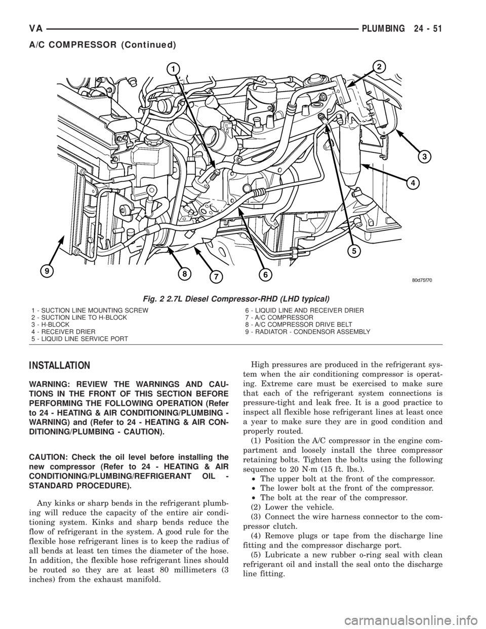
Fig. 2 2.7L Diesel Compressor-RHD (LHD typical)
1 - SUCTION LINE MOUNTING SCREW
2 - SUCTION LINE TO H-BLOCK
3 - H-BLOCK
4 - RECEIVER DRIER
5 - LIQUID LINE SERVICE PORT6 - LIQUID LINE AND RECEIVER DRIER
7 - A/C COMPRESSOR
8 - A/C COMPRESSOR DRIVE BELT
9 - RADIATOR - CONDENSOR ASSEMBLY
VAPLUMBING 24 - 51
A/C COMPRESSOR (Continued)
Page 1193 of 1232
REFRIGERANT
DESCRIPTION
The refrigerant used in this air conditioning sys-
tem is a HydroFluoroCarbon (HFC), type R-134a.
Unlike R-12, which is a ChloroFluoroCarbon (CFC),
R-134a refrigerant does not contain ozone-depleting
chlorine. R-134a refrigerant is a non-toxic, non-flam-
mable, clear, and colorless liquefied gas.
Even though R-134a does not contain chlorine, it
must be reclaimed and recycled just like CFC-type
refrigerants. This is because R-134a is a greenhouse
gas and can contribute to global warming.
OPERATION
R-134a refrigerant is not compatible with R-12
refrigerant in an air conditioning system. Even a
small amount of R-12 added to an R-134a refrigerant
system will cause compressor failure, refrigerant oil
sludge or poor air conditioning system performance.
In addition, the PolyAlkylene Glycol (PAG) synthetic
refrigerant oils used in an R-134a refrigerant system
are not compatible with the mineral-based refriger-
ant oils used in an R-12 refrigerant system.
R-134a refrigerant system service ports, service
tool couplers and refrigerant dispensing bottles have
all been designed with unique fittings to ensure that
an R-134a system is not accidentally contaminated
with the wrong refrigerant (R-12). There are also
labels posted in the engine compartment of the vehi-
cle and on the compressor identifying to service tech-
nicians that the air conditioning system is equipped
with R-134a.
REFRIGERANT OIL
DESCRIPTION
The refrigerant oil used in R-134a refrigerant sys-
tems is a synthetic-based, PolyAlkylene Glycol (PAG),
wax-free lubricant. Mineral-based R-12 refrigerant
oils are not compatible with PAG oils, and should
never be introduced to an R-134a refrigerant system.
There are different PAG oils available, and each
contains a different additive package. The 10PA17
compressor used in this vehicle is designed to use an
ND8 PAG refrigerant oil. Use only refrigerant oil of
this same type to service the refrigerant system.
OPERATION
After performing any refrigerant recovery or recy-
cling operation, always replenish the refrigerant sys-
tem with the same amount of the recommended
refrigerant oil as was removed. Too little refrigerant
oil can cause compressor damage, and too much can
reduce air conditioning system performance.
PAG refrigerant oil is much more hygroscopic than
mineral oil, and will absorb any moisture it comes
into contact with, even moisture in the air. The PAG
oil container should always be kept tightly capped
until it is ready to be used. After use, recap the oil
container immediately to prevent moisture contami-
nation.
STANDARD PROCEDURE - REFRIGERANT OIL
LEVEL
When an air conditioning system is assembled at
the factory, all components except the compressor are
refrigerant oil free. After the refrigerant system has
been charged and operated, the refrigerant oil in the
compressor is dispersed throughout the refrigerant
system. The receiver-drier, evaporator, condenser,
and compressor will each retain a significant amount
of the needed refrigerant oil.
It is important to have the correct amount of oil in
the refrigerant system. This ensures proper lubrica-
tion of the compressor. Too little oil will result in
damage to the compressor. Too much oil will reduce
the cooling capacity of the air conditioning system.
It will not be necessary to check the oil level in the
compressor or to add oil, unless there has been an oil
loss. An oil loss may occur due to a rupture or leak
from a refrigerant line, a connector fitting, a compo-
nent, or a component seal. If a leak occurs, add 30
milliliters (1 fluid ounce) of refrigerant oil to the
refrigerant system after the repair has been made.
Refrigerant oil loss will be evident at the leak point
by the presence of a wet, shiny surface around the
leak.
Refrigerant oil must be added when a receiver/
drier, evaporator coil, or condenser are replaced. See
the Refrigerant Oil Capacities chart. When a com-
pressor is replaced, the refrigerant oil must be
drained from the old compressor and measured.
Drain all of the refrigerant oil from the new compres-
sor, then fill the new compressor with the same
amount of refrigerant oil that was drained out of the
old compressor.
VAPLUMBING 24 - 65
Page 1200 of 1232
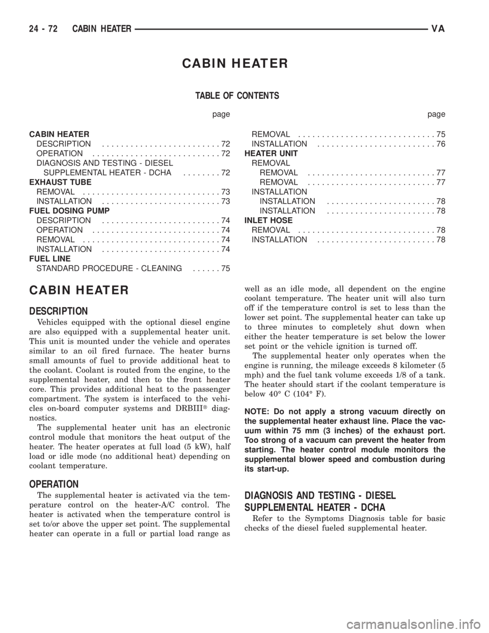
CABIN HEATER
TABLE OF CONTENTS
page page
CABIN HEATER
DESCRIPTION.........................72
OPERATION...........................72
DIAGNOSIS AND TESTING - DIESEL
SUPPLEMENTAL HEATER - DCHA........72
EXHAUST TUBE
REMOVAL.............................73
INSTALLATION.........................73
FUEL DOSING PUMP
DESCRIPTION.........................74
OPERATION...........................74
REMOVAL.............................74
INSTALLATION.........................74
FUEL LINE
STANDARD PROCEDURE - CLEANING......75REMOVAL.............................75
INSTALLATION.........................76
HEATER UNIT
REMOVAL
REMOVAL...........................77
REMOVAL...........................77
INSTALLATION
INSTALLATION.......................78
INSTALLATION.......................78
INLET HOSE
REMOVAL.............................78
INSTALLATION.........................78
CABIN HEATER
DESCRIPTION
Vehicles equipped with the optional diesel engine
are also equipped with a supplemental heater unit.
This unit is mounted under the vehicle and operates
similar to an oil fired furnace. The heater burns
small amounts of fuel to provide additional heat to
the coolant. Coolant is routed from the engine, to the
supplemental heater, and then to the front heater
core. This provides additional heat to the passenger
compartment. The system is interfaced to the vehi-
cles on-board computer systems and DRBIIItdiag-
nostics.
The supplemental heater unit has an electronic
control module that monitors the heat output of the
heater. The heater operates at full load (5 kW), half
load or idle mode (no additional heat) depending on
coolant temperature.
OPERATION
The supplemental heater is activated via the tem-
perature control on the heater-A/C control. The
heater is activated when the temperature control is
set to/or above the upper set point. The supplemental
heater can operate in a full or partial load range aswell as an idle mode, all dependent on the engine
coolant temperature. The heater unit will also turn
off if the temperature control is set to less than the
lower set point. The supplemental heater can take up
to three minutes to completely shut down when
either the heater temperature is set below the lower
set point or the vehicle ignition is turned off.
The supplemental heater only operates when the
engine is running, the mileage exceeds 8 kilometer (5
mph) and the fuel tank volume exceeds 1/8 of a tank.
The heater should start if the coolant temperature is
below 40É C (104É F).
NOTE: Do not apply a strong vacuum directly on
the supplemental heater exhaust line. Place the vac-
uum within 75 mm (3 inches) of the exhaust port.
Too strong of a vacuum can prevent the heater from
starting. The heater control module monitors the
supplemental blower speed and combustion during
its start-up.DIAGNOSIS AND TESTING - DIESEL
SUPPLEMENTAL HEATER - DCHA
Refer to the Symptoms Diagnosis table for basic
checks of the diesel fueled supplemental heater.
24 - 72 CABIN HEATERVA
Page 1212 of 1232
BACKLITE - BULKHEAD TRIM PANEL -
INSTALLATION.......................23-81
BACKLITE - BULKHEAD TRIM PANEL -
REMOVAL..........................23-81
BACKUP LAMP BULB - INSTALLATION.....8L-6
BACKUP LAMP BULB - REMOVAL........8L-5
BALANCE - STANDARD PROCEDURE,
TIRE AND WHEEL.....................22-3
BALL JOINT - INSTALLATION, LOWER......2-6
BALL JOINT - REMOVAL, LOWER..........2-6
BAR - DESCRIPTION, STABILIZER.........2-9
BAR - INSTALLATION, STABILIZER.....2-15,2-9
BAR - OPERATION, STABILIZER...........2-9
BAR - REMOVAL, STABILIZER........2-15,2-9
BASE BRAKE, SPECIFICATIONS............5-6
BASE BRAKE SYSTEM - DIAGNOSIS AND
TESTING.............................5-2
BASECOAT/CLEARCOAT FINISH -
DESCRIPTION.......................23-74
BATTERY - DESCRIPTION...............8F-6
BATTERY - DIAGNOSIS AND TESTING.....8F-7
BATTERY - OPERATION.................8F-7
BATTERY CABLES - DESCRIPTION.......8F-14
BATTERY CABLES - DIAGNOSIS AND
TESTING...........................8F-14
BATTERY CABLES - INSTALLATION.......8F-16
BATTERY CABLES - OPERATION.........8F-14
BATTERY CABLES - REMOVAL..........8F-16
BATTERY CHARGING - STANDARD
PROCEDURE.........................8F-8
BATTERY ELECTROLYTE LEVEL -
STANDARD PROCEDURE, CHECKING.....8F-12
BATTERY HOLDDOWN - DESCRIPTION....8F-14
BATTERY HOLDDOWN - INSTALLATION . . . 8F-14
BATTERY HOLDDOWN - REMOVAL.......8F-14
BATTERY INSTALLATION, INSTALLATION
- AUXILIARY........................8F-13
BATTERY INSTALLATION, INSTALLATION
- UNDER HOOD......................8F-13
BATTERY REMOVAL, REMOVAL -
AUXILIARY..........................8F-13
BATTERY REMOVAL, REMOVAL - UNDER
HOOD..............................8F-12
BATTERY SYSTEM - CLEANING...........8F-5
BATTERY SYSTEM - DESCRIPTION........8F-1
BATTERY SYSTEM - DIAGNOSIS AND
TESTING............................8F-2
BATTERY SYSTEM - INSPECTION.........8F-6
BATTERY SYSTEM - OPERATION.........8F-2
BATTERY SYSTEM SPECIAL TOOLS,
SPECIAL TOOLS......................8F-6
BATTERY TESTER - STANDARD
PROCEDURE, USING MICRO 420........8F-11
BATTERY TRAY - DESCRIPTION.........8F-16
BATTERY TRAY - INSTALLATION.........8F-16
BATTERY TRAY - OPERATION...........8F-16
BATTERY TRAY - REMOVAL............8F-16
BEAM HEADLAMP BULB -
INSTALLATION, HIGH.................8L-17
BEAM HEADLAMP BULB -
INSTALLATION, LOW..................8L-19
BEAM HEADLAMP BULB - REMOVAL,
HIGH..............................8L-17
BEAM HEADLAMP BULB - REMOVAL,
LOW ..............................8L-18
BEAM INDICATOR - DESCRIPTION, HIGH . . 8J-17
BEAM INDICATOR - OPERATION, HIGH....8J-17
BEARING - INSTALLATION, CENTER........3-9
BEARING - INSTALLATION, HUB...........2-5
BEARING - INSTALLATION, OUTPUT
SHAFT............................21-122
BEARING - REMOVAL, CENTER...........3-8
BEARING - REMOVAL, HUB..............2-4
BEARING - REMOVAL, OUTPUT SHAFT . . . 21-122
BEARINGS/SEALS - INSTALLATION, AXLE . . 3-17
BEARINGS/SEALS - INSTALLATION, AXLE
HUB................................3-20
BEARINGS/SEALS - REMOVAL, AXLE......3-17
BEARINGS/SEALS - REMOVAL, AXLE
HUB
................................3-20
BELT - DIAGNOSIS AND TESTING,
ACCESSORY DRIVE
.....................7-5
BELT & RETRACTOR - INSTALLATION,
FRONT SEAT
........................8O-21
BELT & RETRACTOR - INSTALLATION,
REAR SEAT
.........................8O-29
BELT & RETRACTOR - REMOVAL, FRONT
SEAT
..............................8O-19BELT & RETRACTOR - REMOVAL, REAR
SEAT ..............................8O-27
BELT BUCKLE - INSTALLATION, FRONT
SEAT ..............................8O-23
BELT BUCKLE - REMOVAL, FRONT SEAT . . 8O-22
BELT SWITCH - DESCRIPTION, SEAT.....8O-31
BELT SWITCH - OPERATION, SEAT.......8O-31
BELT TENSIONER - DESCRIPTION, SEAT . . 8O-31
BELT TENSIONER - OPERATION, SEAT....8O-32
BELT TENSIONERS - DESCRIPTION........7-5
BELT TENSIONERS - OPERATION..........7-5
BELT TURNING LOOP ADJUSTER -
INSTALLATION, SEAT.................8O-34
BELT TURNING LOOP ADJUSTER -
REMOVAL, SEAT.....................8O-33
BELT WEATHERSTRIP - INSTALLATION,
FRONT DOOR INNER..................23-87
BELT WEATHERSTRIP - INSTALLATION,
FRONT DOOR OUTER.................23-87
BELT WEATHERSTRIP - REMOVAL,
FRONT DOOR INNER..................23-87
BELT WEATHERSTRIP - REMOVAL,
FRONT DOOR OUTER.................23-87
BELTS - INSTALLATION, DRIVE............7-8
BELTS - REMOVAL, DRIVE...............7-8
BEZEL - INSTALLATION, ACCESSORY
SWITCH............................23-54
BEZEL - INSTALLATION, CLUSTER.......23-54
BEZEL - INSTALLATION, INSTRUMENT
PANEL CENTER......................23-55
BEZEL - REMOVAL, ACCESSORY SWITCH . 23-54
BEZEL - REMOVAL, CLUSTER...........23-53
BEZEL - REMOVAL, INSTRUMENT PANEL
CENTER............................23-55
BLADE - DESCRIPTION, WIPER.........8R-15
BLADE - INSTALLATION, WIPER.........8R-16
BLADE - OPERATION, WIPER...........8R-15
BLADE - REMOVAL, WIPER............8R-16
BLEED PROCEDURE, STANDARD
PROCEDURE - POWER STEERING
PUMP FILL.........................19-14
BLEEDING - STANDARD PROCEDURE,
MANUAL.............................5-4
BLEEDING - STANDARD PROCEDURE,
MASTER CYLINDER...................5-17
BLEEDING - STANDARD PROCEDURE,
PRESSURE...........................5-5
BLOCK - DESCRIPTION, BLOWER
MOTOR RESISTOR...................24-16
BLOCK - DIAGNOSIS AND TESTING,
BLOWER MOTOR RESISTOR............24-16
BLOCK - INSTALLATION, BLOWER
MOTOR RESISTOR...................24-17
BLOCK - OPERATION, BLOWER MOTOR
RESISTOR..........................24-16
BLOCK - REMOVAL, BLOWER MOTOR
RESISTOR..........................24-16
BLOCK #1 - DESCRIPTION, FUSE......8W-97-2
BLOCK #1 - INSTALLATION, FUSE.....8W-97-3
BLOCK #1 - OPERATION, FUSE.......8W-97-2
BLOCK #1 - REMOVAL, FUSE.........8W-97-3
BLOCK #2 - DESCRIPTION, FUSE......8W-97-3
BLOCK #2 - OPERATION, FUSE.......8W-97-3
BLOCK HEATER - INSTALLATION,
ENGINE.............................7-14
BLOCK HEATER - REMOVAL, ENGINE......7-14
BLOCK JOURNALS - STANDARD
PROCEDURE, MEASURE CRANKSHAFT
....9-35
BLOWER MOTOR - INSTALLATION
. . 24-33,24-40
BLOWER MOTOR - REMOVAL
......24-32,24-39
BLOWER MOTOR RELAY - DESCRIPTION
. . 24-23
BLOWER MOTOR RELAY - DIAGNOSIS
AND TESTING
.......................24-24
BLOWER MOTOR RELAY -
INSTALLATION
.......................24-24
BLOWER MOTOR RELAY - OPERATION
. . . 24-23
BLOWER MOTOR RELAY - REMOVAL
.....24-24
BLOWER MOTOR RESISTOR BLOCK -
DESCRIPTION
.......................24-16
BLOWER MOTOR RESISTOR BLOCK -
DIAGNOSIS AND TESTING
.............24-16
BLOWER MOTOR RESISTOR BLOCK -
INSTALLATION
.......................24-17
BLOWER MOTOR RESISTOR BLOCK -
OPERATION
.........................24-16
BLOWER MOTOR RESISTOR BLOCK -
REMOVAL
..........................24-16BLOWER MOTOR SWITCH -
DESCRIPTION..................24-17,24-22
BLOWER MOTOR SWITCH - DIAGNOSIS
AND TESTING..................24-17,24-23
BLOWER MOTOR SWITCH -
INSTALLATION.......................24-23
BLOWER MOTOR SWITCH - OPERATION . . 24-17,
24-22
BLOWER MOTOR SWITCH - REMOVAL . . . 24-17,
24-23
BODY & CABLE - INSTALLATION,
ANTENNA...........................8A-1
BODY & CABLE - REMOVAL, ANTENNA....8A-1
BODY PANEL REPAIR - STANDARD
PROCEDURE, PLASTIC.................23-3
BOLT INSPECTION - STANDARD
PROCEDURE, CYLINDER HEAD...........9-21
BOOST PRESSURE SENSOR -
DESCRIPTION.......................14-17
BOOST PRESSURE SENSOR -
DIAGNOSIS AND TESTING.............14-18
BOOST PRESSURE SENSOR -
INSTALLATION.......................14-18
BOOST PRESSURE SENSOR -
OPERATION.........................14-18
BOOST PRESSURE SENSOR - REMOVAL . . 14-18
BOOSTER - DESCRIPTION, POWER
BRAKE..............................5-19
BOOSTER - DIAGNOSIS AND TESTING,
MASTER CYLINDER/POWER.............5-16
BOOSTER - INSTALLATION, POWER
BRAKE..............................5-19
BOOSTER - OPERATION, POWER BRAKE....5-19
BOOSTER - REMOVAL, POWER BRAKE....5-19
BORES - STANDARD PROCEDURE,
MEASURING CYLINDER................9-34
BOX - INSTALLATION, GLOVE...........23-56
BOX - REMOVAL, GLOVE..............23-56
B-PILLAR TRIM - INSTALLATION........23-69
B-PILLAR TRIM - REMOVAL............23-68
BRACKET - INSTALLATION, LICENSE
PLATE .............................23-47
BRACKET - INSTALLATION, PASSENGER
AIRBAG............................8O-27
BRACKET - INSTALLATION, REAR VIEW
MIRROR SUPPORT...................23-72
BRACKET - REMOVAL, LICENSE PLATE . . . 23-47
BRACKET - REMOVAL, PASSENGER
AIRBAG............................8O-27
BRAKE - CLEANING, REAR DRUM IN
HAT ................................5-27
BRAKE - DESCRIPTION, CONTROLLER
ANTILOCK...........................8E-3
BRAKE - INSTALLATION, CONTROLLER
ANTILOCK...........................8E-3
BRAKE - REMOVAL, CONTROLLER
ANTILOCK...........................8E-3
BRAKE BOOSTER - DESCRIPTION,
POWER.............................5-19
BRAKE BOOSTER - INSTALLATION,
POWER.............................5-19
BRAKE BOOSTER - OPERATION, POWER . . . 5-19
BRAKE BOOSTER - REMOVAL, POWER....5-19
BRAKE CABLES - ADJUSTMENT,
PARKING............................5-25
BRAKE FLUID - DESCRIPTION............0-3
BRAKE FLUID CONTAMINATION -
DIAGNOSIS AND TESTING..............5-14
BRAKE FLUID LEVEL - STANDARD
PROCEDURE.........................5-14
BRAKE FLUID, SPECIFICATIONS..........5-14
BRAKE INDICATOR - DESCRIPTION,
BRAKE/PARK........................8J-11
BRAKE INDICATOR - OPERATION,
BRAKE/PARK........................8J-12
BRAKE LAMP SWITCH - INSTALLATION....8L-6
BRAKE LAMP SWITCH - REMOVAL.......8L-6
BRAKE, SPECIAL TOOLS - PARK.........5-23
BRAKE, SPECIFICATIONS - BASE..........5-6
BRAKE SWITCH - INSTALLATION, PARK . . . 8L-20
BRAKE SWITCH - REMOVAL, PARK
......8L-20
BRAKE SYSTEM - DIAGNOSIS AND
TESTING, BASE
........................5-2
BRAKE WEAR INDICATOR -
DESCRIPTION
.......................8J-12
BRAKE WEAR INDICATOR - OPERATION
. . . 8J-12
BRAKE/PARK BRAKE INDICATOR -
DESCRIPTION
.......................8J-11
2 INDEXVA
Description Group-Page Description Group-Page Description Group-Page
Page 1214 of 1232
CIRCUIT BREAKER - OPERATION......8W-97-2
CIRCUIT INFORMATION - DESCRIPTION . 8W-01-5
CLAMP PLATES - INSTALLATION,
SPRING..............................2-8
CLAMP PLATES - REMOVAL, SPRING......2-8
CLASSIFICATION - STANDARD
PROCEDURE, INJECTOR...............14-22
CLEARANCE LAMP BULB -
INSTALLATION........................8L-8
CLEARANCE LAMP BULB - REMOVAL.....8L-8
CLEARANCE LAMP UNIT -
INSTALLATION........................8L-9
CLEARANCE LAMP UNIT - REMOVAL......8L-8
CLOCK - DESCRIPTION................8J-13
CLOCK - OPERATION..................8J-14
CLOCKSPRING - DESCRIPTION.........8O-12
CLOCKSPRING - INSTALLATION.........8O-15
CLOCKSPRING - OPERATION...........8O-13
CLOCKSPRING - REMOVAL............8O-14
CLOCKSPRING CENTERING - STANDARD
PROCEDURE........................8O-13
CLOGGED INDICATOR - DESCRIPTION,
FUEL FILTER........................8J-15
CLOGGED INDICATOR - OPERATION,
FUEL FILTER........................8J-15
CLUSTER - DESCRIPTION, INSTRUMENT . . . 8J-2
CLUSTER - DIAGNOSIS AND TESTING,
INSTRUMENT........................8J-7
CLUSTER - INSTALLATION, INSTRUMENT . . 8J-9
CLUSTER - INSTALLATION, TOP COVER . . . 23-62
CLUSTER - OPERATION, INSTRUMENT.....8J-5
CLUSTER - REMOVAL, INSTRUMENT......8J-7
CLUSTER - REMOVAL, TOP COVER......23-62
CLUSTER BEZEL - INSTALLATION........23-54
CLUSTER BEZEL - REMOVAL...........23-53
CLUTCH - ASSEMBLY, FREEWHEELING . . 21-107
CLUTCH - DESCRIPTION, A/C
COMPRESSOR........................24-8
CLUTCH - DESCRIPTION,
FREEWHEELING.....................21-105
CLUTCH - DISASSEMBLY,
FREEWHEELING.....................21-106
CLUTCH - INSTALLATION, FAN DRIVE
VISCOUS............................7-16
CLUTCH - OPERATION, A/C
COMPRESSOR........................24-8
CLUTCH - OPERATION, FREEWHEELING . . 21-105
CLUTCH - REMOVAL, FAN DRIVE
VISCOUS............................7-16
CLUTCH AIR GAP - STANDARD
PROCEDURE, COMPRESSOR............24-9
CLUTCH B1 - ASSEMBLY, HOLDING.....21-113
CLUTCH B1 - DISASSEMBLY, HOLDING . . 21-112
CLUTCH B2 - ASSEMBLY, HOLDING.....21-116
CLUTCH B2 - DISASSEMBLY, HOLDING . . 21-115
CLUTCH BREAK-IN - STANDARD
PROCEDURE, COMPRESSOR............24-9
CLUTCH COIL - DIAGNOSIS AND
TESTING, COMPRESSOR...............24-12
CLUTCH K1 - ASSEMBLY, DRIVING.......21-75
CLUTCH K1 - DISASSEMBLY, DRIVING....21-74
CLUTCH K2 - ASSEMBLY, DRIVING.......21-78
CLUTCH K2 - DISASSEMBLY, DRIVING....21-76
CLUTCH K3 - ASSEMBLY, DRIVING.......21-80
CLUTCH K3 - DISASSEMBLY, DRIVING....21-80
CLUTCH/COIL - INSPECTION,
COMPRESSOR.......................24-10
CLUTCHES - DESCRIPTION, DRIVING.....21-72
CLUTCHES - DESCRIPTION, HOLDING . . . 21-111
CLUTCHES - OPERATION, DRIVING......21-72
CLUTCHES - OPERATION, HOLDING.....21-112
CODES - SPECIFICATIONS, PAINT........23-74
COIL - DIAGNOSIS AND TESTING,
COMPRESSOR CLUTCH...............24-12
COLUMN OPENING COVER -
INSTALLATION, STEERING.............23-66
COLUMN OPENING COVER - REMOVAL,
STEERING..........................23-66
COMPRESSION TESTING ENGINE -
STANDARD PROCEDURE.................9-3
COMPRESSOR - DESCRIPTION, A/C......24-49
COMPRESSOR - INSTALLATION, A/C
.....24-51
COMPRESSOR - OPERATION, A/C
........24-49
COMPRESSOR - REMOVAL, A/C
.........24-50
COMPRESSOR CLUTCH - DESCRIPTION,
A/C
................................24-8
COMPRESSOR CLUTCH - OPERATION,
A/C
................................24-8COMPRESSOR CLUTCH AIR GAP -
STANDARD PROCEDURE................24-9
COMPRESSOR CLUTCH BREAK-IN -
STANDARD PROCEDURE................24-9
COMPRESSOR CLUTCH COIL -
DIAGNOSIS AND TESTING.............24-12
COMPRESSOR CLUTCH/COIL -
INSPECTION........................24-10
COMPRESSOR NOISE - DIAGNOSIS AND
TESTING...........................24-49
CONDENSER - DESCRIPTION, A/C.......24-52
CONDENSER - INSTALLATION, A/C.......24-52
CONDENSER - OPERATION, A/C.........24-52
CONDENSER - REMOVAL, A/C..........24-52
CONDITIONER - DESCRIPTION, HEATER
AND AIR ............................24-1
CONDITIONER - OPERATION, HEATER
AND AIR ............................24-2
CONNECTING FUEL LINES - STANDARD
PROCEDURE, DISCONNECTING...........14-2
CONNECTING ROD - DESCRIPTION,
PISTON.............................9-40
CONNECTING RODS - STANDARD
PROCEDURE, CHECKING AND
REPAIRING..........................9-40
CONNECTOR - INSTALLATION........8W-01-9
CONNECTOR - REMOVAL............8W-01-8
CONNECTOR, GROUND AND SPLICE
INFORMATION - DESCRIPTION........8W-01-5
CONNECTOR/GROUND/SPLICE LOCATION
- DESCRIPTION....................8W-91-1
CONTACT - DESCRIPTION, PARK/
NEUTRAL..........................21-139
CONTACT - OPERATION, PARK/NEUTRAL . 21-140
CONTAMINATION - DIAGNOSIS AND
TESTING, BRAKE FLUID................5-14
CONTAMINATION - DIAGNOSIS AND
TESTING, FLUID....................21-102
CONTINUITY - STANDARD PROCEDURE,
TESTING.........................8W-01-8
CONTROL ARM - INSTALLATION, LOWER . . . 2-6
CONTROL ARM - REMOVAL, LOWER.......2-6
CONTROL INDICATOR - DESCRIPTION,
TRACTION..........................8J-24
CONTROL INDICATOR - OPERATION,
TRACTION..........................8J-24
CONTROL MALFUNCTION INDICATOR -
DESCRIPTION, TRACTION..............8J-25
CONTROL MALFUNCTION INDICATOR -
OPERATION, TRACTION................8J-25
CONTROL MODULE - DESCRIPTION......24-24
CONTROL MODULE - DESCRIPTION,
AIRBAG.............................8O-8
CONTROL MODULE - DESCRIPTION,
ENGINE.............................8E-3
CONTROL MODULE - DESCRIPTION,
TRANSMISSION.......................8E-5
CONTROL MODULE - DIAGNOSIS AND
TESTING...........................24-24
CONTROL MODULE - INSTALLATION.....24-25
CONTROL MODULE - INSTALLATION,
AIRBAG............................8O-11
CONTROL MODULE - INSTALLATION,
ENGINE.............................8E-4
CONTROL MODULE - OPERATION.......24-24
CONTROL MODULE - OPERATION,
AIRBAG.............................8O-9
CONTROL MODULE - OPERATION,
TRANSMISSION.......................8E-5
CONTROL MODULE - REMOVAL.........24-24
CONTROL MODULE - REMOVAL, AIRBAG . 8O-10
CONTROL MODULE - REMOVAL, ENGINE . . . 8E-4
CONTROLLER - INSTALLATION, ALB......5-15
CONTROLLER - REMOVAL, ALB..........5-15
CONTROLLER ANTILOCK BRAKE -
DESCRIPTION........................8E-3
CONTROLLER ANTILOCK BRAKE -
INSTALLATION........................8E-3
CONTROLLER ANTILOCK BRAKE -
REMOVAL...........................8E-3
CONVERTER - DESCRIPTION, TORQUE . . . 21-141
CONVERTER - INSTALLATION, CATALYTIC . . 11-3
CONVERTER - INSTALLATION, TORQUE
. . 21-146
CONVERTER - OPERATION, TORQUE
....21-143
CONVERTER - REMOVAL, CATALYTIC
......11-3
CONVERTER - REMOVAL, TORQUE
......21-146
CONVERTER HUB SEAL - INSTALLATION,
TORQUE
...........................21-147CONVERTER HUB SEAL - REMOVAL,
TORQUE...........................21-147
COOLANT - DESCRIPTION...............7-9
COOLANT - DESCRIPTION, ENGINE........0-1
COOLANT - DESCRIPTION, HOAT..........0-2
COOLANT - STANDARD PROCEDURE,
ADDING ADDITIONAL..................7-11
COOLANT LEVEL SENSOR -
INSTALLATION........................7-13
COOLANT LEVEL SENSOR - REMOVAL.....7-13
COOLANT LOW INDICATOR -
DESCRIPTION.......................8J-14
COOLANT LOW INDICATOR - OPERATION . 8J-14
COOLANT PUMP - DESCRIPTION,
ELECTRIC..........................24-57
COOLANT PUMP - INSTALLATION,
ELECTRIC..........................24-57
COOLANT PUMP - OPERATION,
ELECTRIC..........................24-57
COOLANT PUMP - REMOVAL, ELECTRIC . . 24-57
COOLANT TEMP SENSOR -
DESCRIPTION, ENGINE.................7-14
COOLANT TEMP SENSOR -
INSTALLATION, ENGINE................7-15
COOLANT TEMP SENSOR - REMOVAL,
ENGINE.............................7-14
COOLANT THERMOSTAT -
INSTALLATION, ENGINE................7-16
COOLANT THERMOSTAT - REMOVAL,
ENGINE.............................7-15
COOLER & LINES - INSTALLATION, OIL....9-50
COOLER & LINES - REMOVAL, OIL.......9-50
COOLER AND PLUMBING - CLEANING,
CHARGE AIR.........................11-5
COOLER AND PLUMBING -
DESCRIPTION, CHARGE AIR.............11-4
COOLER AND PLUMBING - INSPECTION,
CHARGE AIR.........................11-5
COOLER AND PLUMBING -
INSTALLATION, CHARGE AIR............11-5
COOLER AND PLUMBING - OPERATION,
CHARGE AIR.........................11-4
COOLER AND PLUMBING - REMOVAL,
CHARGE AIR.........................11-5
COOLER SYSTEM - LEAKS - DIAGNOSIS
AND TESTING, CHARGE AIR.............11-4
COOLER TUBE - INSTALLATION, FLUID . . . 19-14
COOLER TUBE - INSTALLATION, RETURN
HOSE FROM GEAR TO................19-15
COOLER TUBE - INSTALLATION, RETURN
LINE FROM PUMP TO.................19-15
COOLER TUBE - REMOVAL, FLUID.......19-14
COOLER TUBE - REMOVAL, RETURN
HOSE FROM GEAR TO................19-15
COOLER TUBE - REMOVAL, RETURN
LINE FROM PUMP TO.................19-15
COOLING SYSTEM - DIAGNOSIS AND
TESTING.............................7-2
COOLING SYSTEM - OPERATION..........7-1
COOLING SYSTEM - STANDARD
PROCEDURE, DRAINING................7-12
COOLING SYSTEM - STANDARD
PROCEDURE, REFILLING................7-12
COOLING SYSTEM LEAKS - DIAGNOSIS
AND TESTING........................7-10
COOLING SYSTEM REQUIREMENTS -
DESCRIPTION........................24-1
CORE - DESCRIPTION, HEATER.........24-57
CORE - INSTALLATION, HEATER.........24-58
CORE - OPERATION, HEATER...........24-57
CORE - REMOVAL, HEATER............24-58
CORE AND OIL GALLERY PLUGS -
STANDARD PROCEDURE, REPLACING
ENGINE.............................9-34
COVER - CLUSTER - INSTALLATION, TOP . 23-62
COVER - CLUSTER - REMOVAL, TOP.....23-62
COVER - INSTALLATION, CYLINDER
HEAD FRONT.........................9-26
COVER - INSTALLATION, ENGINE..........9-7
COVER - INSTALLATION, STEERING
COLUMN OPENING...................23-66
COVER - INSTALLATION, TIMING CHAIN
. . . 9-60
COVER - INSTALLATION, TOP
...........23-65
COVER - REMOVAL, CYLINDER HEAD
FRONT
..............................9-23
COVER - REMOVAL, ENGINE
..............9-4
COVER - REMOVAL, STEERING COLUMN
OPENING
...........................23-66
4 INDEXVA
Description Group-Page Description Group-Page Description Group-Page
Page 1216 of 1232
DUAL REAR WHEEL INSTALLATION -
STANDARD PROCEDURE...............22-12
DUAL REAR WHEELS - INSTALLATION,
AXLE SHAFTS........................3-19
DUAL REAR WHEELS - REMOVAL, AXLE
SHAFTS.............................3-19
DUCTS - INSTALLATION, DEFROSTER....24-33
DUCTS - INSTALLATION, FLOOR
DISTRIBUTION.......................24-34
DUCTS - INSTALLATION, INSTRUMENT
PANEL.............................24-38
DUCTS - REMOVAL, DEFROSTER........24-33
DUCTS - REMOVAL, FLOOR
DISTRIBUTION.......................24-33
DUCTS - REMOVAL, INSTRUMENT
PANEL.............................24-37
EFFECTS OF INCORRECT FLUID LEVEL -
DIAGNOSIS AND TESTING............21-102
ELECTRIC COOLANT PUMP -
DESCRIPTION.......................24-57
ELECTRIC COOLANT PUMP -
INSTALLATION.......................24-57
ELECTRIC COOLANT PUMP - OPERATION . 24-57
ELECTRIC COOLANT PUMP - REMOVAL . . . 24-57
ELECTRICAL - DESCRIPTION............5-29
ELECTRICAL - OPERATION..............5-29
ELECTROHYDRAULIC UNIT - ASSEMBLY . . 21-95
ELECTROHYDRAULIC UNIT -
DESCRIPTION.......................21-82
ELECTROHYDRAULIC UNIT -
DISASSEMBLY.......................21-92
ELECTROHYDRAULIC UNIT -
INSTALLATION......................21-100
ELECTROHYDRAULIC UNIT - OPERATION . . 21-87
ELECTROHYDRAULIC UNIT - REMOVAL . . . 21-92
ELECTROLYTE LEVEL - STANDARD
PROCEDURE, CHECKING BATTERY.......8F-12
ELECTROSTATIC DISCHARGE (ESD)
SENSITIVE DEVICES - STANDARD
PROCEDURE......................8W-01-7
ELEMENT - DESCRIPTION, HEATED SEAT . . 8G-3
ELEMENT - DIAGNOSIS AND TESTING,
HEATED SEAT ........................8G-3
ELEMENT - INSTALLATION, AIR
CLEANER............................9-20
ELEMENT - OPERATION, HEATED SEAT....8G-3
ELEMENT - REMOVAL, AIR CLEANER......9-20
END - DIAGNOSIS AND TESTING, OUTER
TIE ROD............................19-10
END - INSTALLATION, TIE ROD.........19-11
END - REMOVAL, TIE ROD.............19-11
ENGINE - DESCRIPTION.................9-2
ENGINE - DESCRIPTION, FUEL
REQUIREMENTS - DIESEL...............0-1
ENGINE - DIAGNOSIS AND TESTING,
DIESEL.............................11-2
ENGINE - STANDARD PROCEDURE,
COMPRESSION TESTING................9-3
ENGINE BLOCK HEATER - INSTALLATION . . . 7-14
ENGINE BLOCK HEATER - REMOVAL......7-14
ENGINE CONTROL MODULE -
DESCRIPTION........................8E-3
ENGINE CONTROL MODULE -
INSTALLATION........................8E-4
ENGINE CONTROL MODULE - REMOVAL . . . 8E-4
ENGINE COOLANT - DESCRIPTION.........0-1
ENGINE COOLANT TEMP SENSOR -
DESCRIPTION........................7-14
ENGINE COOLANT TEMP SENSOR -
INSTALLATION........................7-15
ENGINE COOLANT TEMP SENSOR -
REMOVAL...........................7-14
ENGINE COOLANT THERMOSTAT -
INSTALLATION........................7-16
ENGINE COOLANT THERMOSTAT -
REMOVAL...........................7-15
ENGINE CORE AND OIL GALLERY PLUGS
- STANDARD PROCEDURE, REPLACING....9-34
ENGINE COVER - INSTALLATION..........9-7
ENGINE COVER - REMOVAL
..............9-4
ENGINE CRADLE CROSSMEMBER -
INSTALLATION
........................13-8
ENGINE CRADLE CROSSMEMBER -
REMOVAL
...........................13-6
ENGINE OIL - DIESEL ENGINES -
DESCRIPTION
.........................0-3
ENGINE TEMPERATURE GAUGE -
DESCRIPTION
.......................8J-15ENGINE TEMPERATURE GAUGE -
OPERATION.........................8J-15
ENGINES - DESCRIPTION, ENGINE OIL -
DIESEL..............................0-3
ENTRY MODULE - DESCRIPTION,
SENTRY KEY REMOTE.................8Q-2
ENTRY MODULE - INSTALLATION,
SENTRY KEY REMOTE.................8Q-4
ENTRY MODULE - OPERATION, SENTRY
KEY REMOTE........................8Q-3
ENTRY MODULE - REMOVAL, SENTRY
KEY REMOTE........................8Q-3
ENTRY TRANSMITTER - DESCRIPTION,
REMOTE KEYLESS....................8N-2
ENTRY/EXIT LAMP BULB -
INSTALLATION.......................8L-32
ENTRY/EXIT LAMP BULB - REMOVAL.....8L-31
ENTRY/EXIT LAMP UNIT - INSTALLATION . 8L-32
ENTRY/EXIT LAMP UNIT - REMOVAL.....8L-32
EQUIPMENT - STANDARD PROCEDURE,
REFRIGERANT SYSTEM SERVICE........24-46
EVACUATE - STANDARD PROCEDURE,
REFRIGERANT SYSTEM...............24-47
EVAPORATOR - DESCRIPTION, A/C.......24-54
EVAPORATOR - INSTALLATION, A/C......24-55
EVAPORATOR - INSTALLATION, REAR....24-61
EVAPORATOR - OPERATION, A/C........24-54
EVAPORATOR - REMOVAL, A/C..........24-55
EVAPORATOR - REMOVAL, REAR........24-60
EVAPORATOR TEMPERATURE SENSOR -
DESCRIPTION....................24-17,24-25
EVAPORATOR TEMPERATURE SENSOR -
DIAGNOSIS AND TESTING.............24-26
EVAPORATOR TEMPERATURE SENSOR -
INSTALLATION..................24-18,24-26
EVAPORATOR TEMPERATURE SENSOR -
OPERATION....................24-18,24-26
EVAPORATOR TEMPERATURE SENSOR -
REMOVAL.....................24-18,24-26
EXHAUST MANIFOLD - INSTALLATION.....9-59
EXHAUST MANIFOLD - REMOVAL.........9-59
EXHAUST PIPE - INSTALLATION..........11-3
EXHAUST PIPE - REMOVAL.............11-3
EXHAUST TUBE - INSTALLATION........24-73
EXHAUST TUBE - REMOVAL............24-73
EXPANSION VALVE - DESCRIPTION, A/C . . 24-55
EXPANSION VALVE - DIAGNOSIS AND
TESTING, A/C.......................24-56
EXPANSION VALVE - INSTALLATION, A/C . . 24-56
EXPANSION VALVE - INSTALLATION,
REAR..............................24-63
EXPANSION VALVE - OPERATION, A/C....24-55
EXPANSION VALVE - REMOVAL, A/C.....24-56
EXPANSION VALVE - REMOVAL, REAR....24-62
EXTERIOR - DESCRIPTION, LAMPS/
LIGHTING...........................8L-2
EXTERIOR - OPERATION, LAMPS/
LIGHTING...........................8L-3
EXTERIOR - SPECIFICATIONS,
LAMPS/LIGHTING.....................8L-5
EXTERIOR HANDLE - INSTALLATION.....23-16,
23-33,23-36
EXTERIOR HANDLE - REMOVAL . . . 23-16,23-32,
23-36
FAN - INSTALLATION, RADIATOR.........7-13
FAN - REMOVAL, RADIATOR.............7-13
FAN DRIVE VISCOUS CLUTCH -
INSTALLATION........................7-16
FAN DRIVE VISCOUS CLUTCH -
REMOVAL...........................7-16
FASCIA - INSTALLATION, FRONT.........13-2
FASCIA - INSTALLATION, REAR..........13-3
FASCIA - REMOVAL, FRONT.............13-2
FASCIA - REMOVAL, REAR..............13-3
FASTENER IDENTIFICATION -
DESCRIPTION......................Intro.-2
FASTENER USAGE - DESCRIPTION......Intro.-5
FILL - STANDARD PROCEDURE, DRAIN....3-11
FILL - STANDARD PROCEDURE,
TRANSMISSION.....................21-103
FILL AND BLEED PROCEDURE,
STANDARD PROCEDURE - POWER
STEERING PUMP
.....................19-14
FILL DOOR - INSTALLATION, FUEL
.......23-47
FILL DOOR - REMOVAL, FUEL
..........23-47
FILL/CHECK LOCATIONS - INSPECTION,
FLUID
...............................0-4
FILTER - DESCRIPTION, FLUID
.........21-101FILTER - DESCRIPTION, FUEL............14-5
FILTER - INSTALLATION, AIR......24-31,24-39
FILTER - INSTALLATION, FUEL...........14-6
FILTER - INSTALLATION, OIL............9-51
FILTER - OPERATION, FLUID...........21-101
FILTER - OPERATION, FUEL.............14-5
FILTER - REMOVAL, AIR..........24-31,24-39
FILTER - REMOVAL, FUEL...............14-5
FILTER - REMOVAL, OIL................9-51
FILTER - STANDARD PROCEDURES,
DRAINING WATER FROM FUEL...........14-2
FILTER CLOGGED INDICATOR -
DESCRIPTION, FUEL..................8J-15
FILTER CLOGGED INDICATOR -
OPERATION, FUEL....................8J-15
FINESSE SANDING/BUFFING & POLISH -
DESCRIPTION.......................23-75
FINISH - DESCRIPTION, BASECOAT/
CLEARCOAT.........................23-74
FITTING - STANDARD PROCEDURE,
PISTON RING........................9-46
FLARING - STANDARD PROCEDURE,
DOUBLE INVERTED.....................5-8
FLARING - STANDARD PROCEDURE, ISO....5-8
FLOOR DISTRIBUTION DUCTS -
INSTALLATION.......................24-34
FLOOR DISTRIBUTION DUCTS -
REMOVAL..........................24-33
FLOOR MATS - INSTALLATION, CARPETS . 23-70
FLOOR MATS - REMOVAL, CARPETS.......23-69
FLOW (MAF) SENSOR - DESCRIPTION,
MANIFOLD AIR......................14-30
FLOW (MAF) SENSOR - INSTALLATION,
MANIFOLD AIR......................14-31
FLOW (MAF) SENSOR - OPERATION,
MANIFOLD AIR......................14-30
FLOW (MAF) SENSOR - REMOVAL,
MANIFOLD AIR......................14-31
FLUID - DESCRIPTION, BRAKE............0-3
FLUID - DESCRIPTION, POWER
STEERING............................0-3
FLUID - DIAGNOSIS AND TESTING,
CAUSES OF BURNT..................21-102
FLUID - NAG1 - DESCRIPTION,
AUTOMATIC TRANSMISSION.............0-4
FLUID - OPERATION, AUTOMATIC
TRANSMISSION.......................0-4
FLUID AND FILTER - DESCRIPTION.....21-101
FLUID AND FILTER - OPERATION.......21-101
FLUID CAPACITIES - SPECIFICATIONS......0-4
FLUID CONTAMINATION - DIAGNOSIS
AND TESTING......................21-102
FLUID CONTAMINATION - DIAGNOSIS
AND TESTING, BRAKE..................5-14
FLUID COOLER TUBE - INSTALLATION....19-14
FLUID COOLER TUBE - REMOVAL.......19-14
FLUID FILL/CHECK LOCATIONS -
INSPECTION..........................0-4
FLUID INDICATOR - DESCRIPTION,
WASHER...........................8J-27
FLUID INDICATOR - OPERATION,
WASHER...........................8J-27
FLUID LEVEL - DIAGNOSIS AND
TESTING, EFFECTS OF INCORRECT......21-102
FLUID LEVEL - STANDARD PROCEDURE,
BRAKE..............................5-14
FLUID LEVEL SWITCH - DESCRIPTION,
WASHER............................8R-7
FLUID LEVEL SWITCH - OPERATION,
WASHER............................8R-8
FLUID RESERVOIR - INSTALLATION.......5-15
FLUID RESERVOIR - REMOVAL..........5-15
FLUID, SPECIFICATIONS - BRAKE.........5-14
FLUID/FILTER SERVICE - STANDARD
PROCEDURE.......................21-104
FLUSH - SPECIFICATIONS, GAP.........23-88
FLUSHING POWER STEERING SYSTEM -
STANDARD PROCEDURE...............19-13
FLYWHEEL - REMOVAL.................9-39
FOG LAMP BULB - INSTALLATION.......8L-10
FOG LAMP BULB - REMOVAL...........8L-10
FOG LAMP RELAY - INSTALLATION......8L-11
FOG LAMP RELAY - REMOVAL..........8L-10
FOG LAMP SWITCH - INSTALLATION
.....8L-12
FOG LAMP SWITCH - REMOVAL
.........8L-11
FRAME DIMENSIONS - SPECIFICATIONS
. . . 13-4
FREEWHEELING CLUTCH - ASSEMBLY
. . . 21-107
FREEWHEELING CLUTCH - DESCRIPTION
. 21-105
6 INDEXVA
Description Group-Page Description Group-Page Description Group-Page