2005 MERCEDES-BENZ SPRINTER engine coolant
[x] Cancel search: engine coolantPage 1137 of 1232
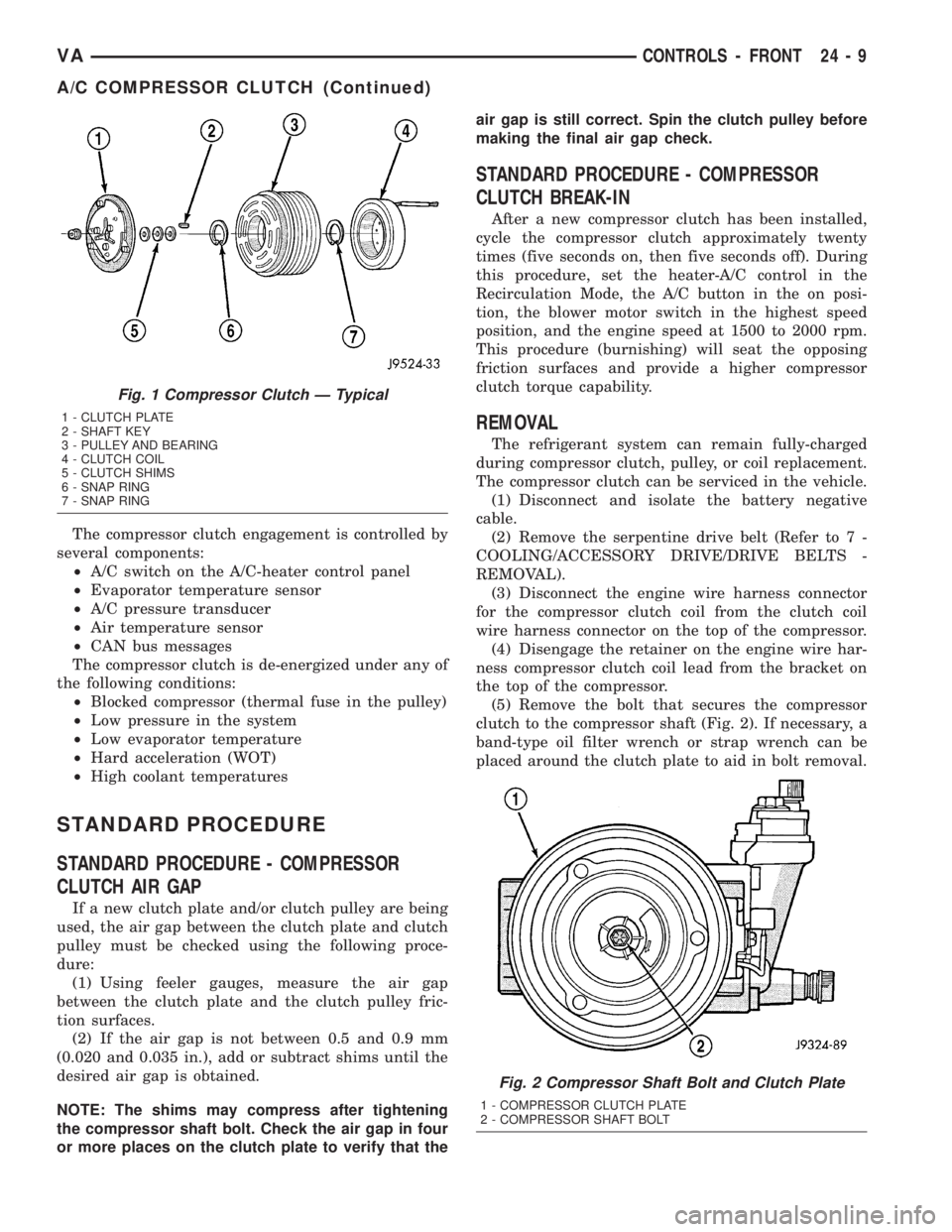
The compressor clutch engagement is controlled by
several components:
²A/C switch on the A/C-heater control panel
²Evaporator temperature sensor
²A/C pressure transducer
²Air temperature sensor
²CAN bus messages
The compressor clutch is de-energized under any of
the following conditions:
²Blocked compressor (thermal fuse in the pulley)
²Low pressure in the system
²Low evaporator temperature
²Hard acceleration (WOT)
²High coolant temperatures
STANDARD PROCEDURE
STANDARD PROCEDURE - COMPRESSOR
CLUTCH AIR GAP
If a new clutch plate and/or clutch pulley are being
used, the air gap between the clutch plate and clutch
pulley must be checked using the following proce-
dure:
(1) Using feeler gauges, measure the air gap
between the clutch plate and the clutch pulley fric-
tion surfaces.
(2) If the air gap is not between 0.5 and 0.9 mm
(0.020 and 0.035 in.), add or subtract shims until the
desired air gap is obtained.
NOTE: The shims may compress after tightening
the compressor shaft bolt. Check the air gap in four
or more places on the clutch plate to verify that theair gap is still correct. Spin the clutch pulley before
making the final air gap check.
STANDARD PROCEDURE - COMPRESSOR
CLUTCH BREAK-IN
After a new compressor clutch has been installed,
cycle the compressor clutch approximately twenty
times (five seconds on, then five seconds off). During
this procedure, set the heater-A/C control in the
Recirculation Mode, the A/C button in the on posi-
tion, the blower motor switch in the highest speed
position, and the engine speed at 1500 to 2000 rpm.
This procedure (burnishing) will seat the opposing
friction surfaces and provide a higher compressor
clutch torque capability.
REMOVAL
The refrigerant system can remain fully-charged
during compressor clutch, pulley, or coil replacement.
The compressor clutch can be serviced in the vehicle.
(1) Disconnect and isolate the battery negative
cable.
(2) Remove the serpentine drive belt (Refer to 7 -
COOLING/ACCESSORY DRIVE/DRIVE BELTS -
REMOVAL).
(3) Disconnect the engine wire harness connector
for the compressor clutch coil from the clutch coil
wire harness connector on the top of the compressor.
(4) Disengage the retainer on the engine wire har-
ness compressor clutch coil lead from the bracket on
the top of the compressor.
(5) Remove the bolt that secures the compressor
clutch to the compressor shaft (Fig. 2). If necessary, a
band-type oil filter wrench or strap wrench can be
placed around the clutch plate to aid in bolt removal.
Fig. 1 Compressor Clutch Ð Typical
1 - CLUTCH PLATE
2 - SHAFT KEY
3 - PULLEY AND BEARING
4 - CLUTCH COIL
5 - CLUTCH SHIMS
6 - SNAP RING
7 - SNAP RING
Fig. 2 Compressor Shaft Bolt and Clutch Plate
1 - COMPRESSOR CLUTCH PLATE
2 - COMPRESSOR SHAFT BOLT
VACONTROLS - FRONT 24 - 9
A/C COMPRESSOR CLUTCH (Continued)
Page 1162 of 1232
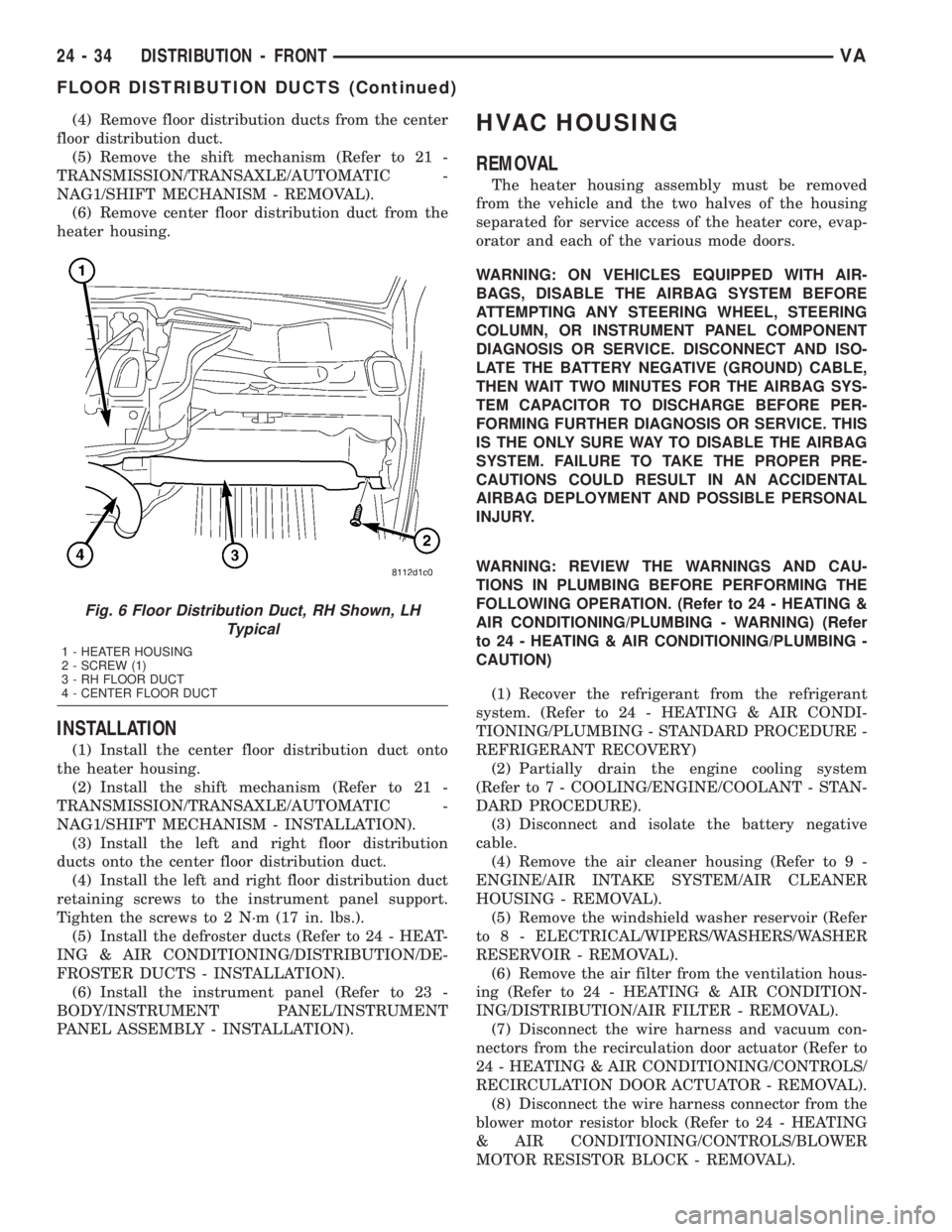
(4) Remove floor distribution ducts from the center
floor distribution duct.
(5) Remove the shift mechanism (Refer to 21 -
TRANSMISSION/TRANSAXLE/AUTOMATIC -
NAG1/SHIFT MECHANISM - REMOVAL).
(6) Remove center floor distribution duct from the
heater housing.
INSTALLATION
(1) Install the center floor distribution duct onto
the heater housing.
(2) Install the shift mechanism (Refer to 21 -
TRANSMISSION/TRANSAXLE/AUTOMATIC -
NAG1/SHIFT MECHANISM - INSTALLATION).
(3) Install the left and right floor distribution
ducts onto the center floor distribution duct.
(4) Install the left and right floor distribution duct
retaining screws to the instrument panel support.
Tighten the screws to 2 N´m (17 in. lbs.).
(5) Install the defroster ducts (Refer to 24 - HEAT-
ING & AIR CONDITIONING/DISTRIBUTION/DE-
FROSTER DUCTS - INSTALLATION).
(6) Install the instrument panel (Refer to 23 -
BODY/INSTRUMENT PANEL/INSTRUMENT
PANEL ASSEMBLY - INSTALLATION).
HVAC HOUSING
REMOVAL
The heater housing assembly must be removed
from the vehicle and the two halves of the housing
separated for service access of the heater core, evap-
orator and each of the various mode doors.
WARNING: ON VEHICLES EQUIPPED WITH AIR-
BAGS, DISABLE THE AIRBAG SYSTEM BEFORE
ATTEMPTING ANY STEERING WHEEL, STEERING
COLUMN, OR INSTRUMENT PANEL COMPONENT
DIAGNOSIS OR SERVICE. DISCONNECT AND ISO-
LATE THE BATTERY NEGATIVE (GROUND) CABLE,
THEN WAIT TWO MINUTES FOR THE AIRBAG SYS-
TEM CAPACITOR TO DISCHARGE BEFORE PER-
FORMING FURTHER DIAGNOSIS OR SERVICE. THIS
IS THE ONLY SURE WAY TO DISABLE THE AIRBAG
SYSTEM. FAILURE TO TAKE THE PROPER PRE-
CAUTIONS COULD RESULT IN AN ACCIDENTAL
AIRBAG DEPLOYMENT AND POSSIBLE PERSONAL
INJURY.
WARNING: REVIEW THE WARNINGS AND CAU-
TIONS IN PLUMBING BEFORE PERFORMING THE
FOLLOWING OPERATION. (Refer to 24 - HEATING &
AIR CONDITIONING/PLUMBING - WARNING) (Refer
to 24 - HEATING & AIR CONDITIONING/PLUMBING -
CAUTION)
(1) Recover the refrigerant from the refrigerant
system. (Refer to 24 - HEATING & AIR CONDI-
TIONING/PLUMBING - STANDARD PROCEDURE -
REFRIGERANT RECOVERY)
(2) Partially drain the engine cooling system
(Refer to 7 - COOLING/ENGINE/COOLANT - STAN-
DARD PROCEDURE).
(3) Disconnect and isolate the battery negative
cable.
(4) Remove the air cleaner housing (Refer to 9 -
ENGINE/AIR INTAKE SYSTEM/AIR CLEANER
HOUSING - REMOVAL).
(5) Remove the windshield washer reservoir (Refer
to 8 - ELECTRICAL/WIPERS/WASHERS/WASHER
RESERVOIR - REMOVAL).
(6) Remove the air filter from the ventilation hous-
ing (Refer to 24 - HEATING & AIR CONDITION-
ING/DISTRIBUTION/AIR FILTER - REMOVAL).
(7) Disconnect the wire harness and vacuum con-
nectors from the recirculation door actuator (Refer to
24 - HEATING & AIR CONDITIONING/CONTROLS/
RECIRCULATION DOOR ACTUATOR - REMOVAL).
(8) Disconnect the wire harness connector from the
blower motor resistor block (Refer to 24 - HEATING
& AIR CONDITIONING/CONTROLS/BLOWER
MOTOR RESISTOR BLOCK - REMOVAL).
Fig. 6 Floor Distribution Duct, RH Shown, LH
Typical
1 - HEATER HOUSING
2 - SCREW (1)
3 - RH FLOOR DUCT
4 - CENTER FLOOR DUCT
24 - 34 DISTRIBUTION - FRONTVA
FLOOR DISTRIBUTION DUCTS (Continued)
Page 1164 of 1232
DISASSEMBLY
(1) Remove the heater and ventilation housings
from the vehicle (Refer to 24 - HEATING & AIR
CONDITIONING/DISTRIBUTION/HVAC HOUSING
- REMOVAL).
(2) Place the heater housing in the upright posi-
tion on a work bench, making allowance for leakage
of fluids.
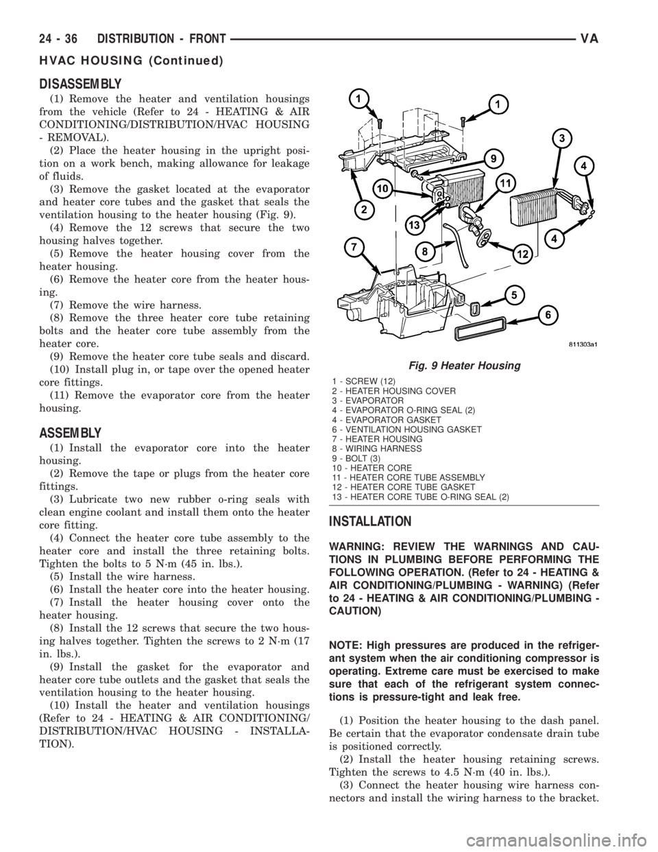
(3) Remove the gasket located at the evaporator
and heater core tubes and the gasket that seals the
ventilation housing to the heater housing (Fig. 9).
(4) Remove the 12 screws that secure the two
housing halves together.
(5) Remove the heater housing cover from the
heater housing.
(6) Remove the heater core from the heater hous-
ing.
(7) Remove the wire harness.
(8) Remove the three heater core tube retaining
bolts and the heater core tube assembly from the
heater core.
(9) Remove the heater core tube seals and discard.
(10) Install plug in, or tape over the opened heater
core fittings.
(11) Remove the evaporator core from the heater
housing.
ASSEMBLY
(1) Install the evaporator core into the heater
housing.
(2) Remove the tape or plugs from the heater core
fittings.
(3) Lubricate two new rubber o-ring seals with
clean engine coolant and install them onto the heater
core fitting.
(4) Connect the heater core tube assembly to the
heater core and install the three retaining bolts.
Tighten the bolts to 5 N´m (45 in. lbs.).
(5) Install the wire harness.
(6) Install the heater core into the heater housing.
(7) Install the heater housing cover onto the
heater housing.
(8) Install the 12 screws that secure the two hous-
ing halves together. Tighten the screws to 2 N´m (17
in. lbs.).
(9) Install the gasket for the evaporator and
heater core tube outlets and the gasket that seals the
ventilation housing to the heater housing.
(10) Install the heater and ventilation housings
(Refer to 24 - HEATING & AIR CONDITIONING/
DISTRIBUTION/HVAC HOUSING - INSTALLA-
TION).
INSTALLATION
WARNING: REVIEW THE WARNINGS AND CAU-
TIONS IN PLUMBING BEFORE PERFORMING THE
FOLLOWING OPERATION. (Refer to 24 - HEATING &
AIR CONDITIONING/PLUMBING - WARNING) (Refer
to 24 - HEATING & AIR CONDITIONING/PLUMBING -
CAUTION)
NOTE: High pressures are produced in the refriger-
ant system when the air conditioning compressor is
operating. Extreme care must be exercised to make
sure that each of the refrigerant system connec-
tions is pressure-tight and leak free.
(1) Position the heater housing to the dash panel.
Be certain that the evaporator condensate drain tube
is positioned correctly.
(2) Install the heater housing retaining screws.
Tighten the screws to 4.5 N´m (40 in. lbs.).
(3) Connect the heater housing wire harness con-
nectors and install the wiring harness to the bracket.
Fig. 9 Heater Housing
1 - SCREW (12)
2 - HEATER HOUSING COVER
3 - EVAPORATOR
4 - EVAPORATOR O-RING SEAL (2)
4 - EVAPORATOR GASKET
6 - VENTILATION HOUSING GASKET
7 - HEATER HOUSING
8 - WIRING HARNESS
9 - BOLT (3)
10 - HEATER CORE
11 - HEATER CORE TUBE ASSEMBLY
12 - HEATER CORE TUBE GASKET
13 - HEATER CORE TUBE O-RING SEAL (2)
24 - 36 DISTRIBUTION - FRONTVA
HVAC HOUSING (Continued)
Page 1165 of 1232
(4) Connect the heater-A/C control cables to the
mode door levers (Refer to 24 - HEATING & AIR
CONDITIONING/CONTROLS/MODE DOOR CABLE
- INSTALLATION).
(5) Reinstall the passenger airbag bracket (Refer
to 8 - ELECTRICAL/RESTRAINTS/PASSENGER
AIRBAG - INSTALLATION).
(6) Reconnect the two bulkhead ground connection
near the instrument cluster area.
(7) Reinstall the defroster, floor distribution and
instrument panel ducts.
(8) Reinstall the instrument panel (Refer to 23 -
BODY/INSTRUMENT PANEL/INSTRUMENT
PANEL ASSEMBLY - INSTALLATION).
(9) Unplug or remove the tape from the opened
refrigerant line fittings.
(10) Lubricate two new rubber o-ring seals with
clean refrigerant oil and install them onto the evap-
orator core fittings.
(11) Connect the refrigerant line terminal block to
the evaporator tubes.
(12) Install the two bolts that secure the refriger-
ant line terminal block to the evaporator. Tighten the
bolts to 5 N´m (45 in. lbs.).
(13) Unplug or remove the tape from the heater
core hoses and tubes.
(14) Connect the heater hoses to the heater core
tubes and install the heater hose clamps.
(15) Install the ventilation housing to the dash
panel.
(16) Install the nuts and washers that secure the
ventilation housing to the dash panel. Tighten the
nuts to 5 N´m (45 in. lbs.).
(17) Connect the wire harness connectors to the
blower motor, blower motor resistor block and the
recirculation door actuator.
(18) Connect the vacuum harness connector to the
recirculation door actuator.
(19) Install the air filter into the ventilation hous-
ing (Refer to 24 - HEATING & AIR CONDITION-
ING/DISTRIBUTION/AIR FILTER -
INSTALLATION).
(20) Install the windshield washer reservoir (Refer
to 8 - ELECTRICAL/WIPERS/WASHERS/WASHER
RESERVOIR - INSTALLATION).
(21) Install the air cleaner housing (Refer to 9 -
ENGINE/AIR INTAKE SYSTEM/AIR CLEANER
HOUSING - INSTALLATION).
(22) Reconnect the battery negative cable.
(23) Refill the engine cooling system (Refer to 7 -
COOLING/ENGINE/COOLANT - STANDARD PRO-
CEDURE).
(24) Evacuate the refrigerant system (Refer to 24 -
HEATING & AIR CONDITIONING/PLUMBING -
STANDARD PROCEDURE - REFRIGERANT SYS-
TEM EVACUATE).(25) Charge the refrigerant system (Refer to 24 -
HEATING & AIR CONDITIONING/PLUMBING -
STANDARD PROCEDURE - REFRIGERANT SYS-
TEM CHARGE).
(26) Start the engine and check for proper opera-
tion of the heating and air conditioning systems.
INSTRUMENT PANEL DUCTS
REMOVAL
(1) Remove the instrument panel (Refer to 23 -
BODY/INSTRUMENT PANEL/INSTRUMENT
PANEL ASSEMBLY - REMOVAL).
(2) Remove the defroster ducts (Refer to 24 -
HEATING & AIR CONDITIONING/DISTRIBUTION/
DEFROSTER DUCTS - REMOVAL).
(3) Remove the floor distribution ducts (Refer to 24
- HEATING & AIR CONDITIONING/DISTRIBU-
TION/FLOOR DISTRIBUTION DUCTS - REMOV-
AL).
(4) If removing the right instrument panel duct,
remove the passenger air bag module and bracket
(Refer to 8 - ELECTRICAL/RESTRAINTS/PASSEN-
GER AIRBAG - REMOVAL).
(5) Remove the screws that secure the left and/or
right instrument panel duct and remove the duct(s)
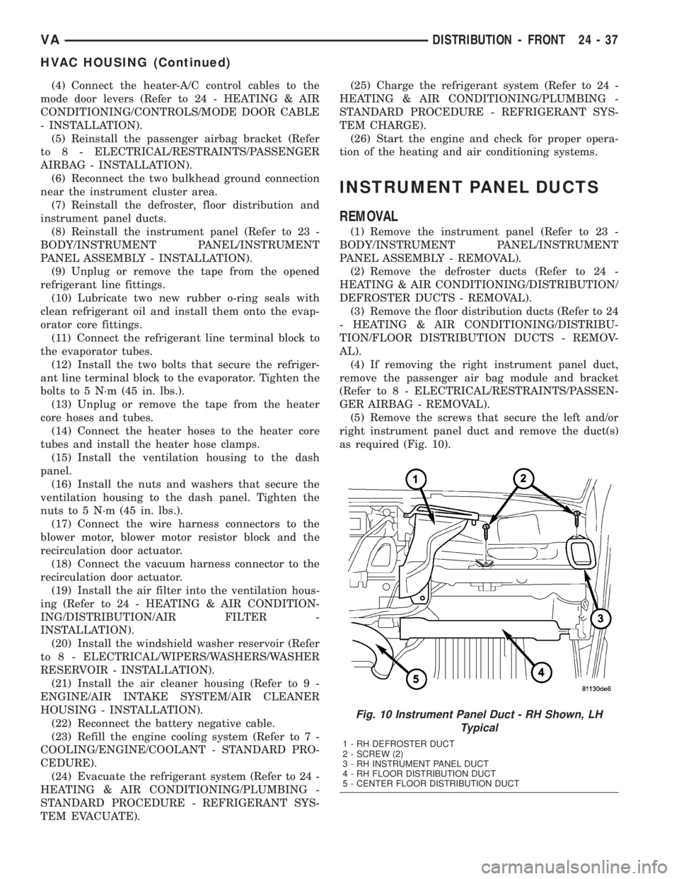
as required (Fig. 10).
Fig. 10 Instrument Panel Duct - RH Shown, LH
Typical
1 - RH DEFROSTER DUCT
2 - SCREW (2)
3 - RH INSTRUMENT PANEL DUCT
4 - RH FLOOR DISTRIBUTION DUCT
5 - CENTER FLOOR DISTRIBUTION DUCT
VADISTRIBUTION - FRONT 24 - 37
HVAC HOUSING (Continued)
Page 1185 of 1232
(9) Install and tighten the nut that secures the
suction line and liquid line fittings to the stud on the
expansion valve. Tighten the nut to 10 N´m (89 in.
lbs.).
(10) Reconnect the battery negative cable.
(11) Evacuate the refrigerant system (Refer to 24 -
HEATING & AIR CONDITIONING/PLUMBING -
STANDARD PROCEDURE).
(12) Charge the refrigerant system (Refer to 24 -
HEATING & AIR CONDITIONING/PLUMBING -
STANDARD PROCEDURE).
ELECTRIC COOLANT PUMP
DESCRIPTION
The electric coolant pump is used on all vehicles.
The pump is located in the left side of the engine
compartment near the battery.
OPERATION
The pump is controlled by the ATC control module
and is only operational under the following condi-
tions:
(1) Vehicle speed below 27 Km/h (17 mph).
(2) Coolant temperature above 65É C (150É F) but
less than 110É C (230 É F).
(3) Any blower speed setting.
(4) Temperature heat setting above the halfway
setting (60% heat).
(5) The pump will turn off at speeds above 48
Km/h (30 mph).
(6) The pump will turn off if the coolant tempera-
ture rises above 110É C (230 É F).
REMOVAL
(1) Disconnect and isolate the battery negative
cable.
(2) Partially drain the engine cooling system
(Refer to 7 - COOLING/ENGINE/COOLANT - STAN-
DARD PROCEDURE).
(3) Disconnect the wire harness connector from the
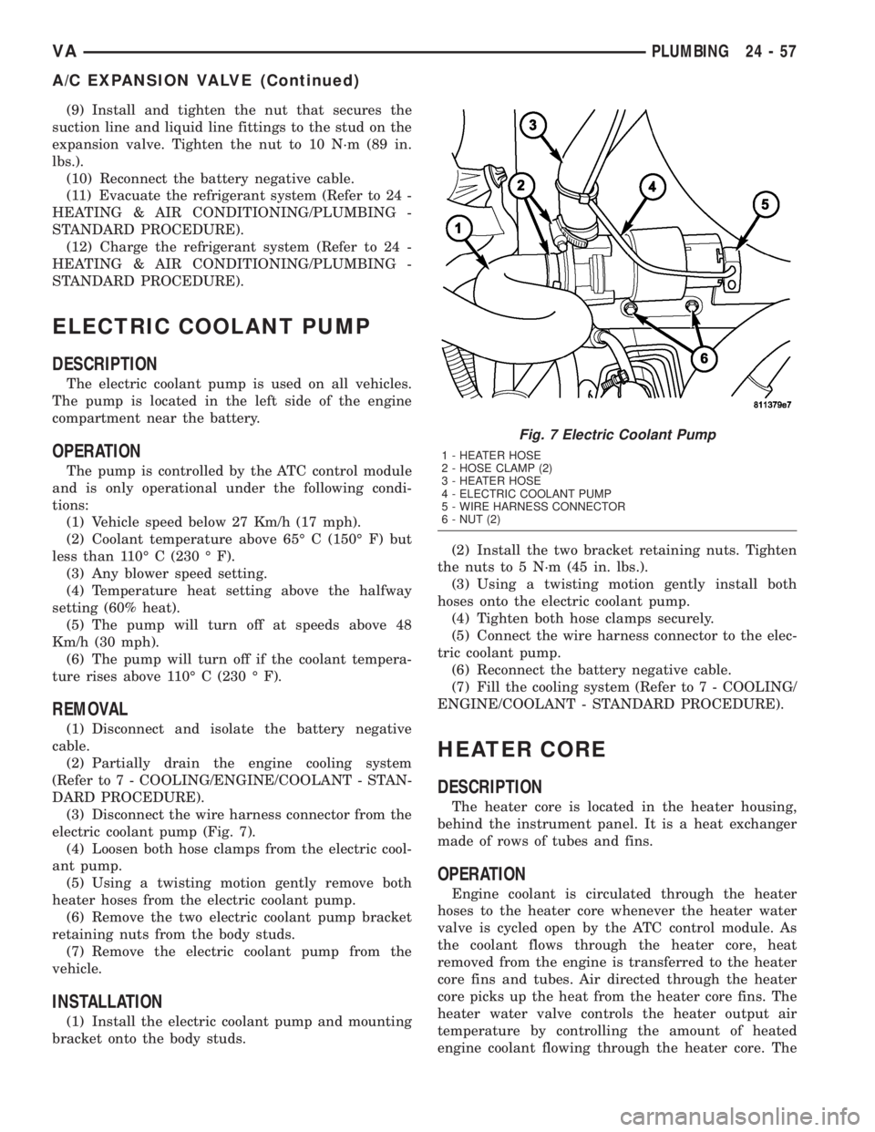
electric coolant pump (Fig. 7).
(4) Loosen both hose clamps from the electric cool-
ant pump.
(5) Using a twisting motion gently remove both
heater hoses from the electric coolant pump.
(6) Remove the two electric coolant pump bracket
retaining nuts from the body studs.
(7) Remove the electric coolant pump from the
vehicle.
INSTALLATION
(1) Install the electric coolant pump and mounting
bracket onto the body studs.(2) Install the two bracket retaining nuts. Tighten
the nuts to 5 N´m (45 in. lbs.).
(3) Using a twisting motion gently install both
hoses onto the electric coolant pump.
(4) Tighten both hose clamps securely.
(5) Connect the wire harness connector to the elec-
tric coolant pump.
(6) Reconnect the battery negative cable.
(7) Fill the cooling system (Refer to 7 - COOLING/
ENGINE/COOLANT - STANDARD PROCEDURE).
HEATER CORE
DESCRIPTION
The heater core is located in the heater housing,
behind the instrument panel. It is a heat exchanger
made of rows of tubes and fins.
OPERATION
Engine coolant is circulated through the heater
hoses to the heater core whenever the heater water
valve is cycled open by the ATC control module. As
the coolant flows through the heater core, heat
removed from the engine is transferred to the heater
core fins and tubes. Air directed through the heater
core picks up the heat from the heater core fins. The
heater water valve controls the heater output air
temperature by controlling the amount of heated
engine coolant flowing through the heater core. The
Fig. 7 Electric Coolant Pump
1 - HEATER HOSE
2 - HOSE CLAMP (2)
3 - HEATER HOSE
4 - ELECTRIC COOLANT PUMP
5 - WIRE HARNESS CONNECTOR
6 - NUT (2)
VAPLUMBING 24 - 57
A/C EXPANSION VALVE (Continued)
Page 1186 of 1232
blower motor speed controls the volume of air flowing
through the heater housing.
The heater core cannot be repaired and, if faulty or
damaged, it must be replaced.
REMOVAL
WARNING: ON VEHICLES EQUIPPED WITH AIR-
BAGS, DISABLE THE AIRBAG SYSTEM BEFORE
ATTEMPTING ANY STEERING WHEEL, STEERING
COLUMN, OR INSTRUMENT PANEL COMPONENT
DIAGNOSIS OR SERVICE. DISCONNECT AND ISO-
LATE THE BATTERY NEGATIVE (GROUND) CABLE,
THEN WAIT TWO MINUTES FOR THE AIRBAG SYS-
TEM CAPACITOR TO DISCHARGE BEFORE PER-
FORMING FURTHER DIAGNOSIS OR SERVICE. THIS
IS THE ONLY SURE WAY TO DISABLE THE AIRBAG
SYSTEM. FAILURE TO TAKE THE PROPER PRE-
CAUTIONS COULD RESULT IN AN ACCIDENTAL
AIRBAG DEPLOYMENT AND POSSIBLE PERSONAL
INJURY.
WARNING: REVIEW THE WARNINGS AND CAU-
TIONS IN THE FRONT OF THIS SECTION BEFORE
PERFORMING THE FOLLOWING OPERATION (Refer
to 24 - HEATING & AIR CONDITIONING/PLUMBING -
WARNING) and (Refer to 24 - HEATING & AIR CON-
DITIONING/PLUMBING - CAUTION).
(1) Remove the heater housing (Refer to 24 -
HEATING & AIR CONDITIONING/DISTRIBUTION/
HVAC HOUSING - REMOVAL).
(2) Disassemble the heater housing to access the
heater core (Refer to 24 - HEATING & AIR CONDI-
TIONING/DISTRIBUTION/HVAC HOUSING - DIS-
ASSEMBLY).
(3) Lift the heater core out of the lower half of the
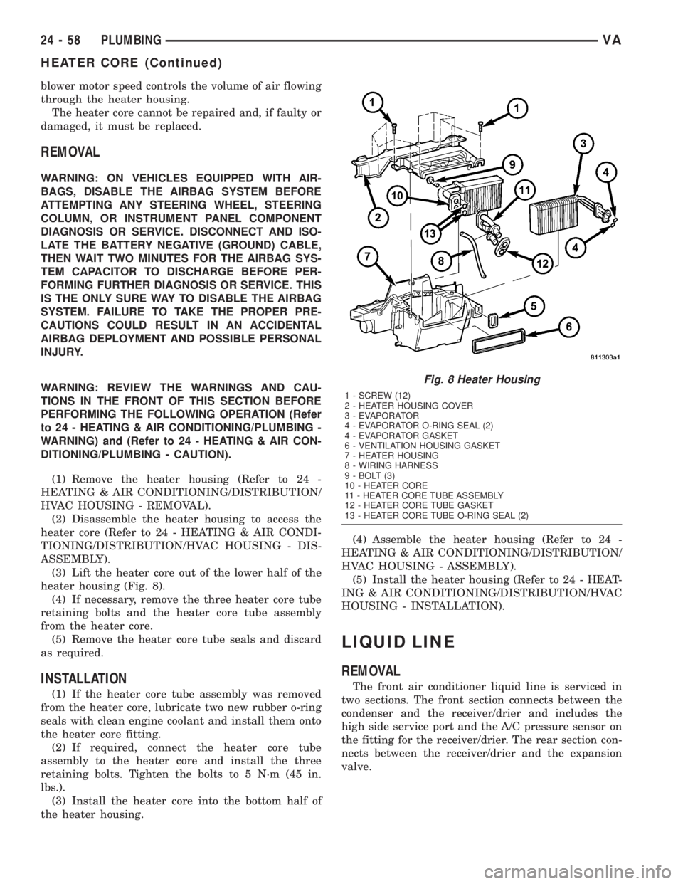
heater housing (Fig. 8).
(4) If necessary, remove the three heater core tube
retaining bolts and the heater core tube assembly
from the heater core.
(5) Remove the heater core tube seals and discard
as required.
INSTALLATION
(1) If the heater core tube assembly was removed
from the heater core, lubricate two new rubber o-ring
seals with clean engine coolant and install them onto
the heater core fitting.
(2) If required, connect the heater core tube
assembly to the heater core and install the three
retaining bolts. Tighten the bolts to 5 N´m (45 in.
lbs.).
(3) Install the heater core into the bottom half of
the heater housing.(4) Assemble the heater housing (Refer to 24 -
HEATING & AIR CONDITIONING/DISTRIBUTION/
HVAC HOUSING - ASSEMBLY).
(5) Install the heater housing (Refer to 24 - HEAT-
ING & AIR CONDITIONING/DISTRIBUTION/HVAC
HOUSING - INSTALLATION).
LIQUID LINE
REMOVAL
The front air conditioner liquid line is serviced in
two sections. The front section connects between the
condenser and the receiver/drier and includes the
high side service port and the A/C pressure sensor on
the fitting for the receiver/drier. The rear section con-
nects between the receiver/drier and the expansion
valve.
Fig. 8 Heater Housing
1 - SCREW (12)
2 - HEATER HOUSING COVER
3 - EVAPORATOR
4 - EVAPORATOR O-RING SEAL (2)
4 - EVAPORATOR GASKET
6 - VENTILATION HOUSING GASKET
7 - HEATER HOUSING
8 - WIRING HARNESS
9 - BOLT (3)
10 - HEATER CORE
11 - HEATER CORE TUBE ASSEMBLY
12 - HEATER CORE TUBE GASKET
13 - HEATER CORE TUBE O-RING SEAL (2)
24 - 58 PLUMBINGVA
HEATER CORE (Continued)
Page 1195 of 1232
(11) Position the metal routing clip around the
suction line and install the routing clip onto the body
stud.
(12) Install the routing clip retaining nut. Tighten
the nut to 5 N´m (45 in. lbs.).
(13) Install the plastic routing clip retainer onto
the suction line.
(14) Reconnect the negative battery cable.
(15) Evacuate the refrigerant system (Refer to 24 -
HEATING & AIR CONDITIONING/PLUMBING -
STANDARD PROCEDURE - REFRIGERANT SYS-
TEM EVACUATE).
(16) Charge the refrigerant system (Refer to 24 -
HEATING & AIR CONDITIONING/PLUMBING -
STANDARD PROCEDURE - REFRIGERANT SYS-
TEM CHARGE).
WATER VALVE
REMOVAL
(1) Disconnect and isolate the battery negative
cable.
(2) Partially drain the engine cooling system
(Refer to 7 - COOLING/ENGINE/COOLANT - STAN-
DARD PROCEDURE).(3) Disconnect the wire harness connector from the
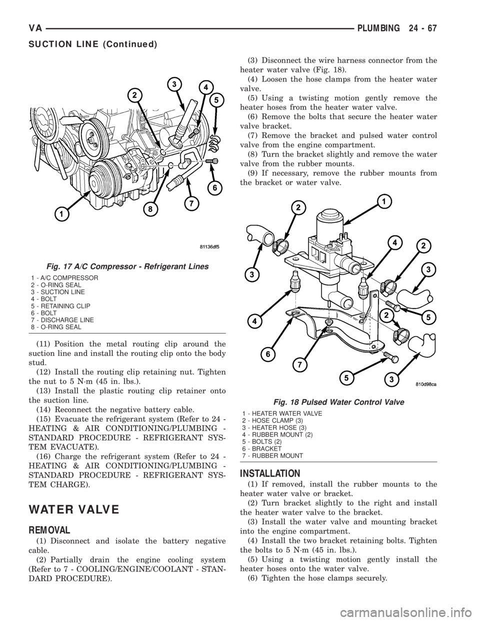
heater water valve (Fig. 18).
(4) Loosen the hose clamps from the heater water
valve.
(5) Using a twisting motion gently remove the
heater hoses from the heater water valve.
(6) Remove the bolts that secure the heater water
valve bracket.
(7) Remove the bracket and pulsed water control
valve from the engine compartment.
(8) Turn the bracket slightly and remove the water
valve from the rubber mounts.
(9) If necessary, remove the rubber mounts from
the bracket or water valve.
INSTALLATION
(1) If removed, install the rubber mounts to the
heater water valve or bracket.
(2) Turn bracket slightly to the right and install
the heater water valve to the bracket.
(3) Install the water valve and mounting bracket
into the engine compartment.
(4) Install the two bracket retaining bolts. Tighten
the bolts to 5 N´m (45 in. lbs.).
(5) Using a twisting motion gently install the
heater hoses onto the water valve.
(6) Tighten the hose clamps securely.
Fig. 17 A/C Compressor - Refrigerant Lines
1 - A/C COMPRESSOR
2 - O-RING SEAL
3 - SUCTION LINE
4 - BOLT
5 - RETAINING CLIP
6 - BOLT
7 - DISCHARGE LINE
8 - O-RING SEAL
Fig. 18 Pulsed Water Control Valve
1 - HEATER WATER VALVE
2 - HOSE CLAMP (3)
3 - HEATER HOSE (3)
4 - RUBBER MOUNT (2)
5 - BOLTS (2)
6 - BRACKET
7 - RUBBER MOUNT
VAPLUMBING 24 - 67
SUCTION LINE (Continued)
Page 1196 of 1232
(7) Connect the wire harness connector to the
heater water valve.
(8) Reconnect the battery negative cable.
(9) Fill the cooling system (Refer to 7 - COOLING/
ENGINE/COOLANT - STANDARD PROCEDURE).
UNDERBODY LINES
REMOVAL
The rear refrigerant lines for the optional rear A/C
system is serviced in four sections. The liquid line for
the optional rear A/C system uses a spring-lock
refrigerant line coupler which requires the use of a
3/8 inch quick-disconnect tool (part of Special Tool,
A/C Line Disconnect Kit 7193).
WARNING: REVIEW THE WARNINGS AND CAU-
TIONS IN THE FRONT OF THIS SECTION BEFORE
PERFORMING THE FOLLOWING OPERATION (Refer
to 24 - HEATING & AIR CONDITIONING/PLUMBING -
WARNING) and (Refer to 24 - HEATING & AIR CON-
DITIONING/PLUMBING - CAUTION).
FRONT LIQUID LINE
(1) Recover the refrigerant from the refrigerant
system (Refer to 24 - HEATING & AIR CONDITION-
ING/PLUMBING - STANDARD PROCEDURE).
(2) Disconnect and isolate the battery negative
cable.
(3) Disconnect the rear section of the front liquid
line from the receiver-drier and the evaporator (Refer
to 24 - HEATING & AIR CONDITIONING/PLUMB-
ING/LIQUID LINE - REMOVAL).
(4) Disconnect the fitting to the intermediate liq-
uid line using Special Tool, A/C Line Disconnect Kit
7193.
(5) Remove the seals from the liquid line fittings
and discard.
(6) Install plug in, or tape over the open liquid line
fittings, the reciever-drier outlet port and the expan-
sion valve ports.
(7) Remove the front liquid line from the engine
compartment.
FRONT SUCTION LINE
(1) Recover the refrigerant from the refrigerant
system (Refer to 24 - HEATING & AIR CONDITION-
ING/PLUMBING - STANDARD PROCEDURE).
(2) Disconnect and isolate the battery negative
cable.
(3) Remove the nut that secures the intermediate
suction line fitting to the stud on the front suction
line tapping plate.
(4) Disconnect the intermediate suction line fitting
from the front suction line tapping plate.(5) Install plug in, or tape over the open suction
line fitting and the front suction line tapping plate
inlet port.
(6) Disconnect the front suction line from the com-
pressor and front evaporator valve (Refer to 24 -
HEATING & AIR CONDITIONING/PLUMBING/
SUCTION LINE - REMOVAL).
(7) Remove the seals from the open suction line fit-
tings and discard.
(8) Install plug in, or tape over the open suction
line fittings, the compressor inlet port and the expan-
sion valve ports.
(9) Remove the front suction line from the engine
compartment.
(10) If necessary, remove the bolt that secures the
compressor portion of the front suction line to the
front suction line tapping plate, separate the front
suction lines, remove and discard the seal and, plug
in, or tape over the open suction line fittings.
INTERMEDIATE REFRIGERANT LINES
(1) Recover the refrigerant from the refrigerant
system (Refer to 24 - HEATING & AIR CONDITION-
ING/PLUMBING/REFRIGERANT - STANDARD
PROCEDURE).
(2) Disconnect and isolate the battery negative
cable.
(3) Disconnect the intermediate liquid line from
the front liquid line using Special Tool, A/C Line Dis-
connect Kit 7193.
(4) Remove the nut that secures the intermediate
suction line fitting to the stud on the front suction
line tapping plate.
(5) Disconnect the intermediate suction line from
the front suction line tapping plate.
(6) Remove the seals from the liquid and suction
line fittings and discard.
(7) Install plug in, or tape over the open suction
and liquid line fittings and the front suction line tap-
ping plate inlet port.
(8) Raise and support the vehicle.
(9) Disconnect the fittings that secure the interme-
diate refrigerant lines to the rear refrigerant lines.
(10) Remove the seals from the open liquid and
suction line fittings and discard.
(11) Install plugs in, or tape over the open liquid
and suction line fittings.
(12) Remove the bolts that secure the two interme-
diate refrigerant line retaining blocks to the vehicle
underbody.
(13) Remove the intermediate section of the rear
refrigerant lines from the vehicle underbody.
REAR REFRIGERANT LINES
(1) Recover the refrigerant from the refrigerant
system (Refer to 24 - HEATING & AIR CONDITION-
24 - 68 PLUMBINGVA
WATER VALVE (Continued)