Page 137 of 356
135 Controls in detail
Good visibility
Rear window defroster
The rear window defroster uses a large
amount of power. To keep the battery
drain to a minimum, switch off the defrost-
er as soon as the rear window is clear. The
defroster is automatically deactivated
after approximately 6 to 17 minutes of
operation depending on the outside tem-
perature.
Activating�
Switch ignition on.
�
Press buttonF (
�page 137).
The indicator lamp on the button
comes on.
Deactivating
�
Press buttonF again.
The indicator lamp on the button goes
out.
Warning!
G
Any accumulation of snow and ice should be
removed from the rear window before driv-
ing. Visibility could otherwise be impaired,
endangering you and others.!If the rear window defroster switches
off too soon and the indicator lamp
starts flashing, this means that too
many electrical consumers are operat-
ing simultaneously and there is insuffi-
cient voltage in the battery. The system
responds automatically by deactivating
the rear window defroster.
As soon as the battery has sufficient
voltage, the rear window defroster au-
tomatically turns itself back on.
Page 144 of 356

142 Controls in detailAutomatic climate control
Residual heat and ventilation
With the engine switched off, it is possible
to continue to heat or ventilate the interior
for up to 30 minutes. This feature makes
use of the residual heat produced by the
engine.
Activating�
Turn the key in the steering lock to
position0 or1 (
�page 33).
�
Press button° (
�page 137).
The indicator lamp on button°
comes on.Deactivating
�
Press button°.
The indicator lamp on button°
goes out.
!If the °button on the automatic
climate control panel starts to flash,
this indicates that the air conditioning
system is losing refrigerant. The com-
pressor has turned itself off. The air
conditioning cannot be turned on
again.
Have the air conditioning system
checked at the nearest authorized
Mercedes-Benz Light Truck Center.
iHow long the system will provide heat-
ing depends on the coolant tempera-
ture and the temperature set by the
operator. The blower will run at lower
speed regardless of the air volume con-
trol setting.
iThe residual heat is automatically
turned off:�
when the ignition is switched on
�
after about 30 minutes
�
if the coolant temperature is too
low
�
if the battery voltage drops
Page 150 of 356
148 Controls in detailPower windowsSynchronizing power windows
The power window must be resynchro-
nized each time�
after the battery has been
disconnected.
�
if the power windows cannot be fully
opened (Express-open) or closed (Ex-
press-close).
Synchronizing the power windows
�
Switch on ignition.
�
Press the power window switches at
the symbolj until the side win-
dows are closed.
Hold the switches for approximately
one second.
The power window are synchronized.
Rear quarter windows*
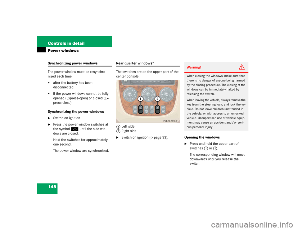
The switches are on the upper part of the
center console.
1Left side
2Right side�
Switch on ignition (
�page 33).Opening the windows
�
Press and hold the upper part of
switches1 or2.
The corresponding window will move
downwards until you release the
switch.Warning!
G
When closing the windows, make sure that
there is no danger of anyone being harmed
by the closing procedure. The closing of the
windows can be immediately halted by
releasing the switch.
When leaving the vehicle, always remove the
key from the steering lock, and lock the ve-
hicle. Do not leave children unattended in
the vehicle, or with access to an unlocked
vehicle. Unsupervised use of vehicle equip-
ment may cause an accident and / or seri-
ous personal injury.
Page 154 of 356

152 Controls in detailPower tilt / sliding sunroof*Fully opening (Express-open) the power
tilt / sliding sunroof�
To open the tilt / sliding sunroof, move
the sunroof switch past the resistance
point in the direction of arrow2 and
release.
The tilt / sliding sunroof almost opens
completely.
�
Move the sunroof switch again briefly
in the direction of arrow2.
The tilt / sliding sunroof almost opens
completely.
Stopping the power tilt / sliding sunroof
during Express-open
�
Move the sunroof switch in any direc-
tion.
The movement of the tilt / sliding sun-
roof stops.Synchronizing the power tilt / sliding
sunroof
The tilt / sliding sunroof must be
synchronized�
after the battery has been
disconnected or discharged
�
after the tilt / sliding sunroof has been
closed manually (
�page 271)
�
after a malfunction
�
the tilt / sliding sunroof does not open
smoothly
�
Remove the respective fuse from the
fuse box (
�page 297).
�
Reinsert the fuse in the fuse box.
�
Switch on ignition.
�
Move and hold the sunroof switch in
the direction of arrow1 or4 until
the tilt / sliding sunroof is fully raised at
the rear or completely closed.
Keep holding the sunroof switch in the
direction of arrow1 or4 for approx-
imately one second.
The tilt / sliding sunroof is synchro-
nized.
Page 173 of 356
171 Controls in detail
Useful features
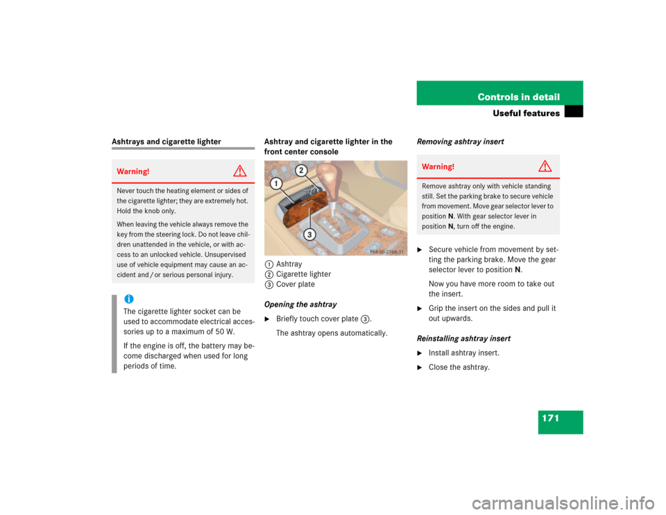
Ashtrays and cigarette lighter Ashtray and cigarette lighter in the
front center console
1Ashtray
2Cigarette lighter
3Cover plate
Opening the ashtray
�
Briefly touch cover plate3.
The ashtray opens automatically.Removing ashtray insert
�
Secure vehicle from movement by set-
ting the parking brake. Move the gear
selector lever to positionN.
Now you have more room to take out
the insert.
�
Grip the insert on the sides and pull it
out upwards.
Reinstalling ashtray insert
�
Install ashtray insert.
�
Close the ashtray.
Warning!
G
Never touch the heating element or sides of
the cigarette lighter; they are extremely hot.
Hold the knob only.
When leaving the vehicle always remove the
key from the steering lock. Do not leave chil-
dren unattended in the vehicle, or with ac-
cess to an unlocked vehicle. Unsupervised
use of vehicle equipment may cause an ac-
cident and / or serious personal injury.iThe cigarette lighter socket can be
used to accommodate electrical acces-
sories up to a maximum of 50 W.
If the engine is off, the battery may be-
come discharged when used for long
periods of time.
Warning!
G
Remove ashtray only with vehicle standing
still. Set the parking brake to secure vehicle
from movement. Move gear selector lever to
positionN. With gear selector lever in
positionN, turn off the engine.
Page 175 of 356
173 Controls in detail
Useful features
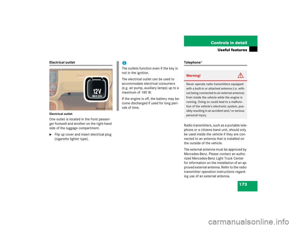
Electrical outletElectrical outletOne outlet is located in the front passen-
ger footwell and another on the right-hand
side of the luggage compartment.�
Flip up cover and insert electrical plug
(cigarette lighter type).
Telephone*
Radio transmitters, such as a portable tele-
phone or a citizens band unit, should only
be used inside the vehicle if they are con-
nected to an antenna that is installed on
the outside of the vehicle.
The external antenna must be approved by
Mercedes-Benz. Please contact an autho-
rized Mercedes-Benz Light Truck Center
for information on the installation of an ap-
proved external antenna. Refer to the radio
transmitter operation instructions regard-
ing use of an external antenna.
iThe outlets function even if the key is
not in the ignition.
The electrical outlet can be used to
accommodate electrical consumers
(e.g. air pump, auxiliary lamps) up to a
maximum of 180 W.
If the engine is off, the battery may be-
come discharged if used for long peri-
ods of time.
Warning!
G
Never operate radio transmitters equipped
with a built-in or attached antenna (i.e. with-
out being connected to an external antenna)
from inside the vehicle while the engine is
running. Doing so could lead to a malfunc-
tion of the vehicle’s electronic system, pos-
sibly resulting in an accident and / or serious
personal injury.
Page 177 of 356
175 Controls in detail
Useful features
The Tele Aid system
(Telematic Alarm Identification on
Demand)
The Tele Aid system consists of three
types of response:�
automatic and manual emergency
�
roadside assistance and
�
information
The Tele Aid system is operational provid-
ing that the vehicle’s battery is charged,
properly connected, not damaged and cel-
lular and GPS coverage is available.
The speaker volume of a Tele Aid call can
be adjusted using the volume control on
the MCS unit.
�
To activate, press the SOS button, the
Roadside Assistance button• or
the Information button¡, depend-
ing on the type of response required.Shortly after the completion of your ac-
quaintance call, you will receive a user ID
and password. By visiting
www.mbusa.com and selecting “Tele Aid”
(USA only), you will have access to account
information, remote door unlock, profile
and more.System self-check
Initially, after switching on ignation, mal-
functions are detected and indicated (the
indicator lamps in the SOS button, the
Roadside Assistance button• and the
Information button¡ stay on longer
than 10 seconds or do not come on). The
message
TELE AID - VISIT WORKSHOP
ap-
pears for approx. 10 seconds in the MCS
display.
iThe SOS button, the Roadside Assis-
tance button• and the Information
button¡ are located in the over-
head control panel.!The Tele Aid system utilizes the cellular
network for communication and the
GPS (G
lobal P
ositioning S
ystem) satel-
lites for vehicle location. If either of
these signals are unavailable, the Tele
Aid system may not function and if this
occurs, assistance must be summoned
by other means.
Page 230 of 356

228 OperationEngine compartment1Cap
2COLD LEVEL mark
The coolant level should reach the COLD
LEVEL mark2 in the reservoir.
�
Using a rag, turn the cap slowly approx-
imately one half turn to the left to re-
lease any excess pressure.
�
Continue turning the cap to the left and
remove it.
�
Add coolant as required.
�
Replace and tighten cap.
For more information on coolant, see the
“Technical data” section (
�page 316).
Battery
The battery is located in the engine com-
partment.
The battery should always be sufficiently
charged in order to achieve its rated ser-
vice life. Refer to Maintenance Booklet for
battery maintenance intervals.
If you use your vehicle mostly for
short-distance trips, you will need to have
the battery charge checked more frequent-
ly.
When replacing batteries, always use
batteries approved by Mercedes-Benz.
If you do not intend to operate your vehicle
for an extended period of time, consult an
authorized Mercedes-Benz Light Truck
Center about steps you need to observe.
iIf the engine is already at its regular op-
erating temperature, the coolant may
be approximately 0.6 in (1.5 cm) above
the COLD LEVEL mark.