Page 407 of 498

405 Practical hints
Replacing bulbs
Rear lamps
Notes on bulb replacement
�
Only use 12 volt bulbs of the same type
and with the specified watt rating.
�
Switch lights off before changing a bulb
to prevent short circuits.
�
Always use a clean lint-free cloth when
handling bulbs.
�
Your hands should be dry and free of oil
and grease.
�
If the newly installed bulb does not
come on, visit an authorized
Mercedes-Benz Center.
�
Have the LEDs and bulbs for the follow-
ing lamps replaced by an authorized
Mercedes-Benz Center.�
Additional turn signal lamps in the
exterior rear view mirrors
�
High mounted brake lamp
�
Bi-Xenon* lamps
�
Front fog lamps
Lamp
Type
7
High mounted brake
lamp
LED
8
Brake lamp
P 21 W
9
Turn signal lamp
P 21 W
a
Tail, parking and stand-
ing lamp, side marker
P 21/4 W
W 5 W
b
Backup lamp
P 21 W
c
License plate lamps
C 5 W
d
Rear fog lamp, driver’s
side
P 21/4 W
Warning!
G
Keep bulbs out of reach of children.
Bulbs and bulb sockets can be very hot. Al-
low the lamp to cool down before changing
a bulb.
Halogen lamps contain pressurized gas. A
bulb can explode if you:�
touch or move it when hot
�
drop the bulb
�
scratch the bulb
Wear eye and hand protection.
Because of high voltage in Xenon lamps, it is
dangerous to replace the bulb or repair the
lamp and its components. We recommend
that you have such work done by a qualified
technician.
iHave the headlamp adjustment
checked regularly.
Page 410 of 498
408 Practical hintsReplacing bulbsFront lamps Bi-Xenon*-type
1Bulb socket for turn signal lamp
2Housing cover for high beam flasher,
parking and standing lamp
3Housing cover for Bi-Xenon* headlamp4Bulb holder for high beam flasher bulb
5Bulb socket for parking and standing
lamp bulbHigh beam bulb for high beam flasher
�
Turn housing cover2 counterclock-
wise and remove it.
�
Turn bulb holder4 with the bulb coun-
terclockwise and remove it.
�
Pull the bulb at its socket out of bulb
holder4.
�
Insert the new bulb so that its socket
locates in the recess of bulb holder4
and is level to it.
�
Reinsert bulb holder4 with the bulb in
the lamp and turn clockwise.
�
Align housing cover2 and turn it
clockwise.
Warning!
G
Do not remove the cover
3
for the Bi-Xe-
non* headlamp. Because of high voltage in
xenon lamps, it is dangerous to replace the
bulb or repair the lamp and its components.
We recommend that you have such work
done by a qualified technician.
Page 413 of 498

411 Practical hints
Replacing wiper blades
�Replacing wiper blades
Removing wiper blades�
Remove SmartKey from starter switch.
�
Fold the wiper arm forward.1Unlock
2Lock
�
Pull the tab in direction of arrow1 and
remove windshield wiper.
Installing wiper blades�
Slide the wiper blade into the cutout on
the wiper arm (see arrows).
�
Slide the tab back in the direction of
arrow2 until it audibly engages.
�
Fold the wiper arm backward to rest on
the windshield. Make sure you hold on
to the wiper when folding the wiper arm
back.
Warning!
G
For safety reasons, switch off wipers and
remove SmartKey from starter switch
(vehicles with KEYLESS-GO*: make sure the
vehicle’s on-board electronics have
status
0) before replacing a wiper blade.
Otherwise, the wiper motor could suddenly
turn on and cause injury.
!Never open the hood when the wiper
arms are folded forward.
Hold on to the wiper when folding the
wiper arm back. If released, the force
of the impact from the tensioning
spring could crack the windshield.
Do not allow the wiper arms to contact
the windshield glass without a wiper
blade inserted.
Make certain that the wiper blades are
properly installed. Improperly installed
wiper blades may cause windshield
damage.
For your convenience, we recommend
that you have this work carried out by
an authorized Mercedes-Benz Center.
Page 414 of 498
.
�
Turn the steering w")
412 Practical hintsFlat tire
Preparing the vehicle�
Park the vehicle as far as possible from
moving traffic on a hard surface.
�
Turn on the hazard warning flasher
(�page 131).
�
Turn the steering wheel so that the
front wheels are in a straight ahead
position.
�
Set the parking brake (
�page 55).
�
Move the gear selector lever toP.
Vehicles with SmartKey:
�
Turn off the engine (
�page 56).
�
Remove the SmartKey from the starter
switch.Vehicles with SmartKey with
KEYLESS-GO*:
�
Turn off the engine by pressing the
KEYLESS-GO* start/stop button on the
gear selector lever once (
�page 57).
�
Open the driver’s door (this puts the ig-
nition in position0, same as with the
SmartKey removed from the starter
switch). The driver’s door then can be
closed again.
�
Have any passenger exit the vehicle at
a safe distance from the roadway.
Warning!
G
The dimensions of the spare wheel
(Minispare or collapsible tire) are different
from those of the road wheels. As a result,
the vehicle handling characteristics change
when driving with a spare wheel mounted.
Adapt your driving style accordingly.
The spare wheel is for temporary use only.
When driving with spare wheel mounted,
ensure proper tire pressure and do not ex-
ceed a vehicle speed of 50 mph (80 km/h).
Drive to the nearest Mercedes-Benz Center
as soon as possible to have the spare wheel
replaced with a regular road wheel.
Never operate the vehicle with more than
one spare wheel mounted.
iOpen door only when conditions are
safe to do so.
Page 415 of 498
.
Vehicles with Minispare wheel:
�
Take the wheel wrench, the wheel
bolts, an")
413 Practical hints
Flat tire
Mounting the spare wheel
Preparing the vehicle
Prepare the vehicle as described
(�page 412).
Vehicles with Minispare wheel:
�
Take the wheel wrench, the wheel
bolts, and the jack out of the trunk
(�page 389).
�
Take the Minispare wheel out of the
trunk (
�page 393).
Vehicles with collapsible tire
(CLK 55 AMG only):
�
Take the collapsible tire, wheel wrench,
wheel bolts, jack, and electric air pump
out of the trunk (
�page 390).Lifting the vehicle
�
Prevent the vehicle from rolling away
by blocking wheels with wheel chocks
or other sizable objects.
One wheel chock is included with the
vehicle tool kit (
�page 389).
When changing wheel on a level surface:
�
Place the wheel chock in front of and
another sizable object behind the
wheel that is diagonally opposite to the
wheel being changed.
When changing wheel on a hill:
�
Place the wheel chock and another
sizable object on the downhill side
blocking both wheels of the other axle.
Warning!
G
The jack is designed exclusively for jacking
up the vehicle at the jack take-up brackets
built into both sides of the vehicle. To help
avoid personal injury, use the jack only to lift
the vehicle during a wheel change. Never
get beneath the vehicle while it is supported
by the jack. Keep hands and feet away from
the area under the lifted vehicle. Always
firmly set parking brake and block wheels
before raising vehicle with jack.
Do not disengage parking brake while the
vehicle is raised. Be certain that the jack is
always vertical (plumb line) when in use,
especially on hills. Always try to use the jack
on level surface. Make sure the jack arm is
fully seated in the jack take-up bracket. Al-
ways lower the vehicle onto sufficient ca-
pacity jackstands before working under the
vehicle.
Page 416 of 498
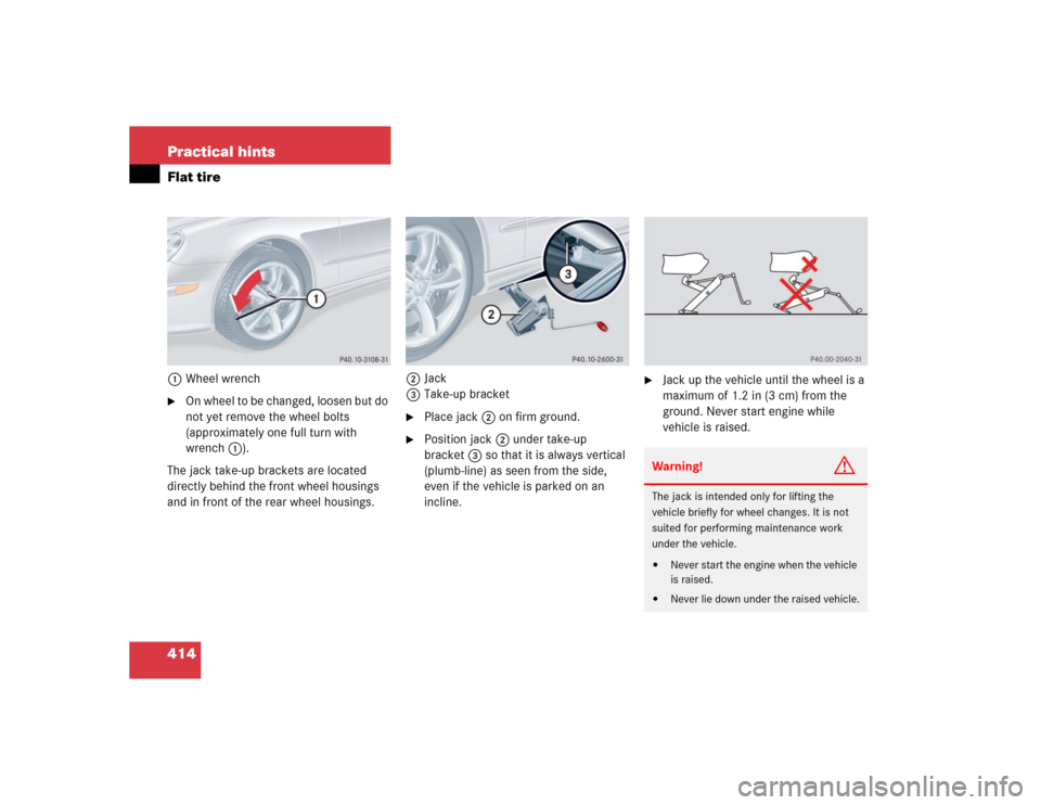
414 Practical hintsFlat tire1Wheel wrench�
On wheel to be changed, loosen but do
not yet remove the wheel bolts
(approximately one full turn with
wrench 1).
The jack take-up brackets are located
directly behind the front wheel housings
and in front of the rear wheel housings.2Jack
3Take-up bracket
�
Place jack2 on firm ground.
�
Position jack2 under take-up
bracket3 so that it is always vertical
(plumb-line) as seen from the side,
even if the vehicle is parked on an
incline.
�
Jack up the vehicle until the wheel is a
maximum of 1.2 in (3 cm) from the
ground. Never start engine while
vehicle is raised.Warning!
G
The jack is intended only for lifting the
vehicle briefly for wheel changes. It is not
suited for performing maintenance work
under the vehicle.�
Never start the engine when the vehicle
is raised.
�
Never lie down under the raised vehicle.
Page 417 of 498

415 Practical hints
Flat tire
Removing the wheel
1Alignment bolt�
Unscrew upper-most wheel bolt and
remove.
�
Replace this wheel bolt with alignment
bolt1 supplied in the tool kit.
�
Remove the remaining bolts.
�
Remove the wheel.Mounting the spare wheel
1Wheel bolt for light alloy rims
2Wheel bolt for Minispare wheel,
collapsible tire, or other steel rims
(located in trunk with spare wheel)
�
Clean contact surfaces of wheel and
wheel hub.
!Do not place wheel bolts in sand or dirt.
This could result in damage to the bolts
and wheel hub threads.
!Wheel bolts2 must be used when
mounting the Minispare wheel,
collapsible tire, or other steel rims. The
use of any wheel bolts other than wheel
bolts2 for the Minispare wheel,
collapsible tire, or other steel rims will
physically damage the vehicle’s
brakes.
!To avoid paint damage, place wheel flat
against hub and hold it there while
installing first wheel bolt.Warning!
G
Always replace wheel bolts that are
damaged or rusted.
Never apply oil or grease to wheel bolts.
Damaged wheel hub threads should be
repaired immediately. Do not continue to
drive under these circumstances! Contact
an authorized Mercedes-Benz Center or call
Roadside Assistance.
Incorrect wheel bolts or improperly tight-
ened wheel bolts can cause the wheel to
come off. This could cause an accident.
Make sure to use the correct wheel bolts.
Page 418 of 498
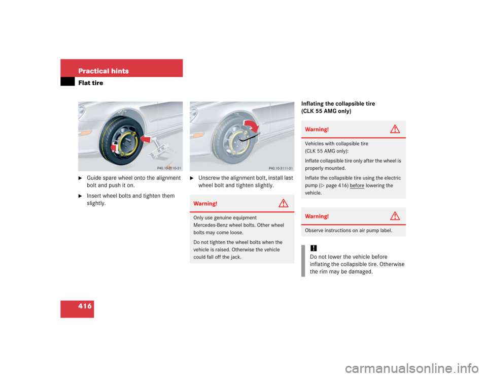
416 Practical hintsFlat tire�
Guide spare wheel onto the alignment
bolt and push it on.
�
Insert wheel bolts and tighten them
slightly.
�
Unscrew the alignment bolt, install last
wheel bolt and tighten slightly.Inflating the collapsible tire
(CLK 55 AMG only)Warning!
G
Only use genuine equipment
Mercedes-Benz wheel bolts. Other wheel
bolts may come loose.
Do not tighten the wheel bolts when the
vehicle is raised. Otherwise the vehicle
could fall off the jack.
Warning!
G
Vehicles with collapsible tire
(CLK 55 AMG only):
Inflate collapsible tire only after the wheel is
properly mounted.
Inflate the collapsible tire using the electric
pump (
�page 416) before
lowering the
vehicle.
Warning!
G
Observe instructions on air pump label.!Do not lower the vehicle before
inflating the collapsible tire. Otherwise
the rim may be damaged.