Page 397 of 474

396 Practical hintsFlat tireThe jack take-up brackets are located
directly behind the front wheel housings
and in front of the rear wheel housings.1 Jack
2 Crank
3 Take-up bracket�
Place jack on firm ground.
�
Position jack 1 under the take-up
bracket 3 so that it is always vertical
(plumb-line) as seen from the side,
even if the vehicle is parked on an
incline.
�
Jack up the vehicle until the wheel is a
maximum of 1.2 in (3 cm) from the
ground. Never start engine while vehi-
cle is raised. Removing the wheel
1 Alignment bolt
�
Unscrew upper-most wheel bolt and
remove.
�
Replace this wheel bolt with the align-
ment bolt 1 supplied in the tool kit.
�
Remove the remaining bolts.
�
Remove the wheel.
Warning!
G
The jack is intended only for lifting the
vehicle briefly for wheel changes. It is not
suited for performing maintenance work un-
der the vehicle.�
Never start the engine when the vehicle
is raised.
�
Never lie down under the raised vehicle.
!Do not place wheel bolts in sand or dirt.
This could result in damage to the bolt
and wheel hub threads.
Page 398 of 474

397
Practical hints
Flat tire
Mounting the spare wheel
1 Wheel bolt for light alloy rims
2 Wheel bolt for light alloy spare wheel
rim size 4
1/2B x15 H2
�
Clean contact surfaces of wheel and
wheel hub.
�
Guide the spare wheel onto the align-
ment bolt and push it on.
�
Insert wheel bolts and tighten them
slightly.
�
Inflate the spare tire using the electric
air pump (
�page 398).
!Wheel bolts 2 must be used when
mounting spare wheel rim
size 4
1/2Bx15 H2 (
�page 422).
The use of any wheel bolts other than
wheel bolts 2 for spare wheel rim
size 4
1/2B x15 H2 can cause physical
damage to the vehicle.
!To avoid paint damage, place wheel flat
against hub and hold it there while
installing first wheel bolt.Warning!
G
Always replace wheel bolts that are dam-
aged or rusted.
Never apply oil or grease to wheel bolts.
Damaged wheel hub threads should be re-
paired immediately. Do not continue to drive
under these circumstances! Contact an
authorized Mercedes-Benz Center or call
Roadside Assistance.
Incorrect wheel bolts or improperly tight-
ened wheel bolts can cause the wheel to
come off. This could cause an accident.
Make sure to use the correct mounting
bolts.
Warning!
G
Inflate spare wheel with collapsible tire only
after the wheel is properly mounted.
Inflate the spare wheel tire using the electric
air pump before lowering the vehicle.
��
Page 399 of 474
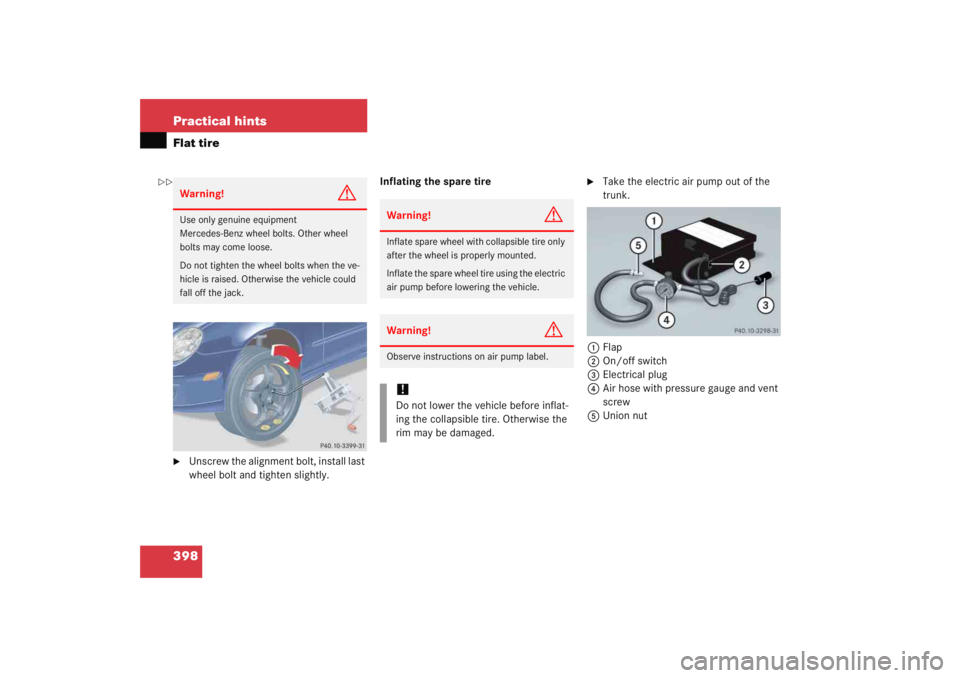
398 Practical hintsFlat tire�
Unscrew the alignment bolt, install last
wheel bolt and tighten slightly.Inflating the spare tire
�
Take the electric air pump out of the
trunk.
1 Flap
2 On/off switch
3 Electrical plug
4 Air hose with pressure gauge and vent
screw
5 Union nut
Warning!
G
Use only genuine equipment
Mercedes-Benz wheel bolts. Other wheel
bolts may come loose.
Do not tighten the wheel bolts when the ve-
hicle is raised. Otherwise the vehicle could
fall off the jack.
Warning!
G
Inflate spare wheel with collapsible tire only
after the wheel is properly mounted.
Inflate the spare wheel tire using the electric
air pump before lowering the vehicle.Warning!
G
Observe instructions on air pump label.!Do not lower the vehicle before inflat-
ing the collapsible tire. Otherwise the
rim may be damaged.
��
Page 400 of 474

399
Practical hints
Flat tire
�
Open flap
1 on electric air pump.
�
Pull out electrical plug 3 and air hose
with pressure gauge 4.
�
Remove the valve cap from valve.
�
Screw air hose 4 onto the tire valve.
�
Insert electrical plug 3 into vehicle
cigarette lighter socket.
�
Turn the SmartKey in the starter switch
to position 1.
�
Press I on electric air pump switch 2.
The electric air pump should now
switch on and inflate the spare tire.
�
Inflate the spare tire to approximately
36 psi (2.5 bar).
This takes about five minutes for the
spare tire. Air hose 4 and union
nut 5 can become hot during infla-
tion. Exercise proper caution to avoid
burning yourself when using the equip-
ment.
�
Press 0on electric air pump switch 2.
�
Turn the SmartKey in the starter switch
to position 0.
�
If the tire pressure is above 36 psi
(2.5 bar), release excess tire pressure
using the vent screw.
�
Detach the electric air pump.
�
Store the electrical plug and the air
hose behind the flap and place the air
pump back in the trunk.
!Do not operate the electric air pump
longer than six minutes without
interruption. Otherwise it may over-
heat.
You may operate the electric air pump
again after it has cooled off.
Warning!
G
Follow recommended inflation pressures.
Do not overinflate tires. Overinflated tires
can result in sudden deflation (blowout) be-
cause they are more likely to become punc-
tured or damaged by road debris, potholes,
etc.
Do not underinflate tires. Underinflated tires
wear unevenly, adversely affect handling
and fuel economy, and are more likely to fail
from being overheated.
Page 401 of 474
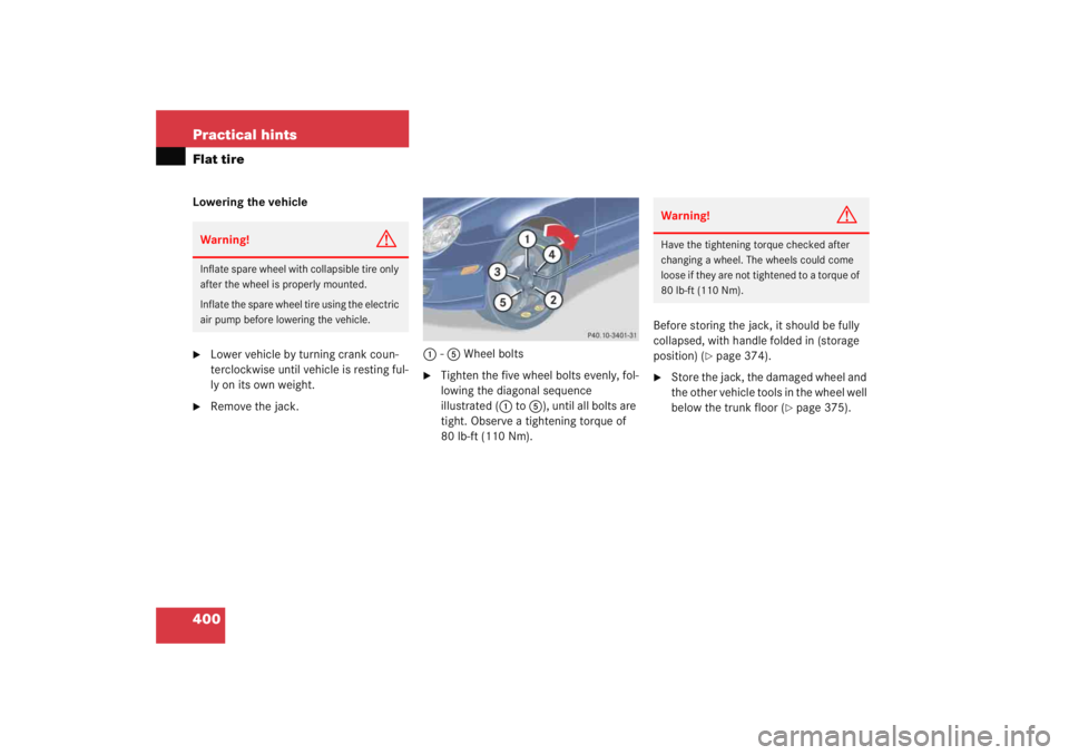
400 Practical hintsFlat tireLowering the vehicle�
Lower vehicle by turning crank coun-
terclockwise until vehicle is resting ful-
ly on its own weight.
�
Remove the jack.1
-5 Wheel bolts
�
Tighten the five wheel bolts evenly, fol-
lowing the diagonal sequence
illustrated ( 1 to 5 ), until all bolts are
tight. Observe a tightening torque of
80 lb-ft (110 Nm). Before storing the jack, it should be fully
collapsed, with handle folded in (storage
position) (
�page 374).
�
Store the jack, the damaged wheel and
the other vehicle tools in the wheel well
below the trunk floor (
�page 375).
Warning!
G
Inflate spare wheel with collapsible tire only
after the wheel is properly mounted.
Inflate the spare wheel tire using the electric
air pump before lowering the vehicle.
Warning!
G
Have the tightening torque checked after
changing a wheel. The wheels could come
loose if they are not tightened to a torque of
80 lb-ft (110 Nm).
Page 420 of 474

419
Technical data
Rims and Tires
� Rims and Tires
Use only tires and rims which have been
specifically developed for your vehicle and
tested and approved by Mercedes-Benz.
Other tires and rims can have detrimental
effects, such as�
poor handling characteristics
�
increased noise
�
increased fuel consumption
!Moreover, tires and rims not approved
by Mercedes-Benz may, under load, ex-
hibit dimensional variations and differ-
ent tire deformation characteristics
that could cause them to come into
contact with the vehicle body or axle
parts. This may result in damage to the
tires or the vehicle.
iFurther information on tires and rims is
available at any authorized
Mercedes-Benz Center. A placard with
the recommended tire inflation
pressures is located on the driver’s
door B-pillar. Some vehicles may have
supplemental tire inflation pressure
information for driving at high speeds
(�page 310) or for vehicle loads less
than the maximum loaded vehicle con-
dition. If such information is provided,
it can be found on the placard located
on the inside of the fuel filler flap. The
tire inflation pressure should be
checked regularly and should only be
adjusted on cold tires. Follow tire
manufacturer’s maintenance recom-
mendation included with vehicle.
Page 438 of 474

Prevents the wheels from locking up
during braking so that the vehicle can
continue to be steered.
Accessory weight (
�page 323)
Air pressure (�pag")
437
Technical terms
ABS
(A
ntilock B
rake S
ystem)
Prevents the wheels from locking up
during braking so that the vehicle can
continue to be steered.
Accessory weight (
�page 323)
Air pressure (�page 323)
Alignment bolt Metal pin with thread. The centering
pin is an aid used when changing a tire
to align the wheel with the wheel hub.
Aspect ratio (�page 323)
Bar (�page 323)
BAS (Brake A
ssist S
ystem)
System for potentially reducing braking
distances in emergency braking situa-
tions. The system is activated when it
senses an emergency based on how
fast the brake is applied. Bead
(
�page 323)
Bi-Xenon headlamps* Headlamps which use an electric arc as
the light source and produce a more in-
tense light than filament headlamps.
Bi-Xenon headlamps produce low
beam and high beam.
CAC (Customer A
ssistance C
enter)
Mercedes-Benz customer service cen-
ter, which can help you with any ques-
tions about your vehicle and provide
assistance in the event of a break-
down.
CAN system (C
ontroller A
rea N
etwork)
Data bus network serving to control ve-
hicle functions such as door locking or
windshield wiping. Cockpit
All instruments, switches, buttons and
indicator/warning lamps in the passen-
ger compartment needed for vehicle
operation and monitoring.
Cold tire inflation pressure (
�page 323)
Collapsible tire An especially compact spare tire that
must be inflated with a provided air
pump before using. It should only be
used to bring the vehicle to the nearest
service station.
COMAND* (Cockpit M
anagement and D
ata Sys-
tem)
Information and operating center for
vehicle sound and communications
systems, including the radio and navi-
gation system, as well as other optional
equipment (CD changer, telephone,
etc.).
Page 440 of 474

Satellite-based system for relaying
geographic location information to and
from vehicles equipped with special re-
ceivers. Employs CD digital")
439
Technical terms
GPS*
(G
lobal P
ositioning S
ystem)
Satellite-based system for relaying
geographic location information to and
from vehicles equipped with special re-
ceivers. Employs CD digital maps for
navigation.
GVW (G
ross V
ehicle W
eight)
(
�page 324)
GVWR (Gross V
ehicle W
eight R
ating)
(
�page 324)
Instrument cluster The displays and indicator/warning
lamps in the driver’s field of vision, in-
cluding the tachometer, speedometer
and fuel gauge. Kickdown
Depressing the accelerator past the
point of resistance shifts the transmis-
sion down to the lowest possible gear.
This very quickly accelerates the vehi-
cle and should not be used for normal
acceleration needs.
Kilopascal (kPa) (
�page 324)
Lock button Button on the door which indicates
whether the door is locked or un-
locked. Pushing the lock button down
on an individual door from inside will
lock that door.
Maintenance System (U.S. vehicles) Maintenance service indicator in the
multifunction display that informs the
driver when the next vehicle mainte-
nance service is due. The Maintenance
System in your vehicle tracks distance
driven and the time elapsed since your
last maintenance service, and calls for
the next maintenance service accord-
ingly. Maximum load rating
(
�page 324)
Maximum loaded vehicle weight (�page 324)
Maximum tire inflation pressure (�page 324)
Memory function* Used to store three individual seat,
steering wheel and mirror positions for
each SmartKey.
MON (Motor O
ctane N
umber)
The Motor Octane Number for gasoline
as determined by a standardized meth-
od. It is an indication of a gasoline's
ability to resist undesired detonation
(knocking). The average of both the
MON (Motor Octane Number) and
->RON (Research Octane Number) is
posted at the pump, also known as
ANTI-KNOCK INDEX.