2005 JEEP LIBERTY change wheel
[x] Cancel search: change wheelPage 119 of 424
Parking Lights, Instrument Panel Lights, and
Headlights
Turn the end cap of the multi-function control lever to the
first detent for parking lights and instrument panel
lights. Turn to the second detent for headlight operation.
To change the brightness of the instrument panel lights,
rotate the center portion of the multi-function control
lever up or down.
High Beam/Low Beam Select Switch
Pull the multi-function control lever towards you to
switch the headlights to HIGH beam. Pull the multi-
function control lever a second time to switch the head-
lights to LOW beam. The “High Beam Indicator Light”
will illuminate when the high beams are on.
Passing Light
You can signal another vehicle with your headlights by
lightly pulling the multi-function control lever toward
the steering wheel. This will cause the headlights to turn
on at high beam and remain on until the lever is released.
The “High Beam Indicator Light” will illuminate when
the high beams are on.
Turn Signals
Move the multi-function control lever up or down and
the arrows on each side of the instrument cluster flash to
show proper operation of the front and rear turn signal
lights. You can signal a lane change by moving the lever
partially up or down without moving beyond the detent.
If either light flashes at a very fast rate, check for a
defective outside light bulb. If an indicator fails to light
when the lever is moved, it would suggest that the fuse
or indicator is defective.
UNDERSTANDING THE FEATURES OF YOUR VEHICLE 119
3
Page 177 of 424
RADIO GENERAL INFORMATION
Radio Broadcast Signals
Your new radio will provide excellent reception under
most operating conditions. Like any system, however, car
radios have performance limitations, due to mobile op-
eration and natural phenomena, which might lead you to
believe your sound system is malfunctioning. To help
you understand and save you concern about these “ap-
parent” malfunctions, you must understand a point or
two about the transmission and reception of radio sig-
nals.
Two Types of Signals
There are two basic types of radio signals... AM or
Amplitude Modulation, in which the transmitted sound
causes the amplitude, or height, of the radio waves to
vary... and FM or Frequency Modulation, in which the
frequency of the wave is varied to carry the sound.
Electrical Disturbances
Radio waves may pick up electrical disturbances during
transmission. They mainly affect the wave amplitude,
and thus remain a part of the AM reception. They
interfere very little with the frequency variations that
carry the FM signal.
AM Reception
AM sound is based on wave amplitude, so AM reception
can be disrupted by such things as lightning, power lines
and neon signs.
FM Reception
Because FM transmission is based on frequency varia-
tions, interference that consists of amplitude variations
can be filtered out, leaving the reception relatively clear,
which is the major feature of FM radio.
NOTE:On vehicles so equipped the radio, steering
wheel radio controls and 6 disc CD/DVD changer will
UNDERSTANDING YOUR INSTRUMENT PANEL 177
4
Page 251 of 424

Standing Water
Avoid driving in standing water deeper than 20 inches,
and reduce speed appropriately to minimize wave ef-
fects. Maximum speed in 20 inches of water is less than 5
mph (8 km/h).
Maintenance
After driving through deep water, inspect your vehicle
fluids and lubricants (engine oil, transmission oil, axle,
transfer case) to assure the fluids have not been contami-
nated. Contaminated fluid (milky, foamy in appearance)
should be flushed/changed as soon as possible to pre-
vent component damage.
Driving In Snow, Mud and Sand
In heavy snow, when pulling a load, or for additional
control at slower speeds, shift the transmission to a low
gear and shift the transfer case to 4L or 4LO if necessary.
Refer to “Four-Wheel Drive Operation” in this section.Do not shift to a lower gear than necessary to maintain
headway. Over-revving the engine can spin the wheels
and traction will be lost.
Avoid abrupt downshifts on icy or slippery roads, be-
cause engine braking may cause skidding and loss of
control.
Hill Climbing
NOTE:Before attempting to climb a hill, determine the
conditions at the crest and/or on the other side.
Before climbing a steep hill,shift the transmission to a
lower gear and shift the transfer case to 4L or 4LO. Use
first gear and 4L or 4LO for very steep hills.
If you stall or begin to lose headwaywhile climbing a
steep hill, allow your vehicle to come to a stop and
immediately apply the brakes. Restart the engine and
shift to R (Reverse). Back slowly down the hill allowing
the compression braking of the engine to help regulate
STARTING AND OPERATING 251
5
Page 267 of 424
WARNING!
•Do not use a tire, wheel size or rating other than that
specified for your vehicle. Some combinations of unap-
proved tires and wheels may change suspension dimen-
sions and performance characteristics, resulting in
changes to steering, handling, and braking of your
vehicle. This can cause unpredictable handling and
stress to steering and suspension components. You
could lose control and have an accident resulting in
serious injury or death. Use only the tire and wheel
sizes with load ratings approved for your vehicle.
•Never use a tire smaller than the minimum tire size
listed on your vehicle’s tire label. Using a smaller tire
could result in tire overloading and failure. You could
lose control and have an accident.
•Failure to equip your vehicle with tires having adequate
speed capability can result in sudden tire failure and
loss of vehicle control.
•Overloading your tires is dangerous. Overloading can
cause tire failure. Use tires of the recommended load
capacity for your vehicle - never overload them.
CAUTION!
Replacing original tires with tires of a different size
may result in false speedometer and odometer read-
ings. Check with your dealer before replacing tires
with a different size.
Alignment and Balance
The suspension components of your vehicle should be
inspected and aligned when needed, to obtain maximum
tire tread life.
Poor suspension alignment may result in:
•reduced tread life;
•uneven tire wear, such as feathering and one-sided
wear;
•vehicle pull to the right or to the left.
STARTING AND OPERATING 267
5
Page 296 of 424
NOTE:If you have added aftermarket accessories to the
spare tire mounted carrier, it cannot exceed a gross
weight of 50 lbs (23 kg) including the weight of the spare
tire.
Preparations For Jacking
Park the vehicle on a firm level surface, avoid ice or
slippery areas,set the parking brakeand place auto-
matic transmission in P (Park), or manual transmission in
R (Reverse). Turn OFF the ignition.
WARNING!
Do not attempt to change a tire on the side of the
vehicle close to moving traffic. Pull far enough off
the road to avoid being hit when operating the jack
or changing the wheel.
•Turn on the Hazard Warning Flasher.
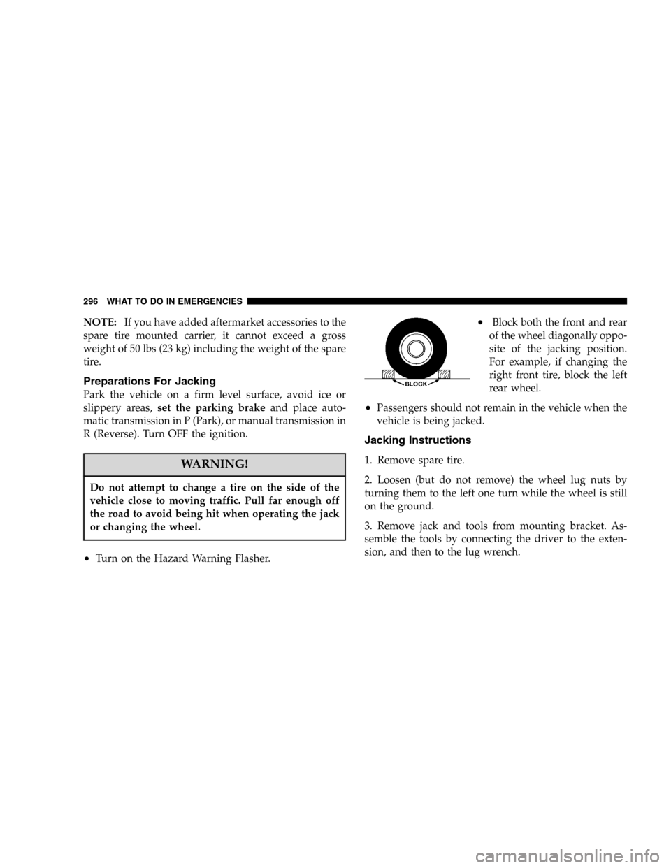
•Block both the front and rear
of the wheel diagonally oppo-
site of the jacking position.
For example, if changing the
right front tire, block the left
rear wheel.
•Passengers should not remain in the vehicle when the
vehicle is being jacked.
Jacking Instructions
1. Remove spare tire.
2. Loosen (but do not remove) the wheel lug nuts by
turning them to the left one turn while the wheel is still
on the ground.
3. Remove jack and tools from mounting bracket. As-
semble the tools by connecting the driver to the exten-
sion, and then to the lug wrench.
296 WHAT TO DO IN EMERGENCIES
Page 297 of 424
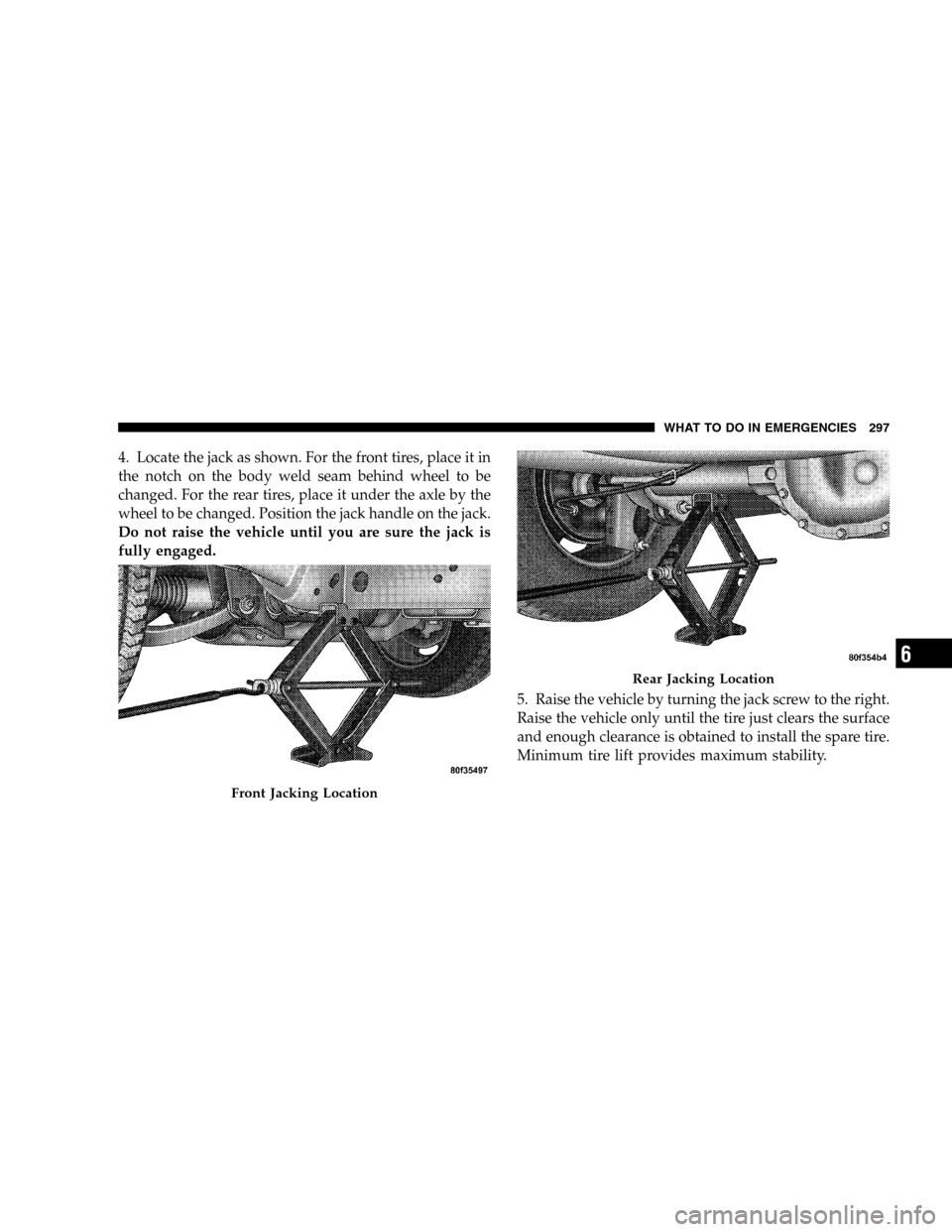
4. Locate the jack as shown. For the front tires, place it in
the notch on the body weld seam behind wheel to be
changed. For the rear tires, place it under the axle by the
wheel to be changed. Position the jack handle on the jack.
Do not raise the vehicle until you are sure the jack is
fully engaged.
5. Raise the vehicle by turning the jack screw to the right.
Raise the vehicle only until the tire just clears the surface
and enough clearance is obtained to install the spare tire.
Minimum tire lift provides maximum stability.
Front Jacking Location
Rear Jacking Location
WHAT TO DO IN EMERGENCIES 297
6