Page 240 of 408

and Traction Control, provides resistance to any wheel
that is slipping to allow additional torque transfer to
wheels with traction.
NOTE:The Quadra-Trac I�system is not appropriate
for conditions where LOW range is recommended. Refer
to “Off-Road Driving Tips” in this section.
Quadra-Trac II�Operating
Instructions/Precautions — If Equipped
The Quadra-Trac II�transfer case is fully automatic in the
normal driving 4 HI mode. The Quadra-Trac II�transfer
case provides three mode positions — four wheel drive
high range, neutral, and four wheel drive low range.
This transfer case is fully automatic in the 4 HI mode.
This transfer case divides engine torque almost evenly
with 48 percent of engine torque to the front axle and 52
percent of engine torque to the rear axle. When speed
differences are increased between the front and rear driveshafts, the transfer case can transmit up to 100 percent of
available engine torque to the front or rear drive shafts.
When additional traction is required, the 4 LOW position
can be used to lock the front and rear driveshafts together
and force the front and rear wheels to rotate at the same
speed. The 4 LOW position is intended for loose, slippery
road surfaces only. Driving in the 4 LOW position on dry
hard surfaced roads may cause increased tire wear and
damage to driveline components.
When operating your vehicle in 4 LOW, the engine speed
is approximately three times that of the 4 HI position at a
given road speed. Take care not to overspeed the engine
and do not exceed 25 mph (40 km/h).
Proper operation of four wheel drive vehicles depends on
tires of equal size, type, and circumference on each
wheel. Any difference will adversely affect shifting and
cause damage to the transfer case.
240 STARTING AND OPERATING
Page 246 of 408

To release the parking brake, pull up slightly, press the
center button, then lower the lever completely.
Be sure the parking brake is fully disengaged before
driving. Failure to do so can lead to brake failure.
NOTE:Parking brake adjustment and maintenance
should be performed by your authorized dealer.
ANTI-LOCK BRAKE SYSTEM
The Anti-Lock Brake System (ABS) is designed to aid the
driver in maintaining vehicle control under adverse
braking conditions. The system operates with a separate
computer to modulate hydraulic pressure to prevent
wheel lock-up and help avoid skidding on slippery
surfaces.
All vehicle wheels and tires must be the same size and
type and tires must be properly inflated to produce
accurate signals for the computer.
WARNING!
Significant over or under inflation of tires, or mixing
sizes of tires or wheels on the vehicle can lead to loss
of braking effectiveness.
The Anti-Lock Brake System conducts a low-speed self-
test at about 12 mph (20 km/h). If you have your foot
lightly on the brake while this test is occurring you may
feel slight pedal movement. The movement can be more
apparent on ice and snow. This is normal.
The Anti-Lock Brake System pump motor runs during
the self-test at 12 mph (20 km/h) and during an ABS stop.
The pump motor makes a low humming noise during
operation, which is normal.
246 STARTING AND OPERATING
Page 254 of 408
MULTI DISPLACEMENT SYSTEM (MDS) - 5.7L
Engine Only
This feature offers improved fuel economy by shutting
off four of the engine’s eight cylinders during light load
and cruise conditions. The system is automatic with no
driver inputs or additional driving skills required.
NOTE:This system must be reset if the vehicle battery
is disconnected. See your authorized dealer for service.
TIRE SAFETY INFORMATION
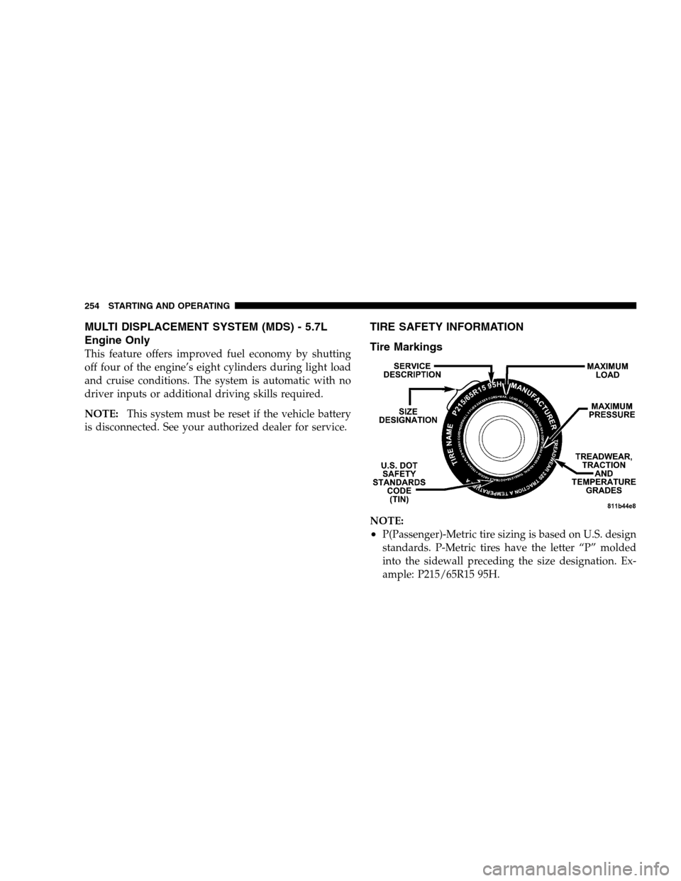
Tire Markings
NOTE:
•P(Passenger)-Metric tire sizing is based on U.S. design
standards. P-Metric tires have the letter “P” molded
into the sidewall preceding the size designation. Ex-
ample: P215/65R15 95H.
254 STARTING AND OPERATING
Page 255 of 408
•European Metric tire sizing is based on European
design standards. Tires designed to this standard have
the tire size molded into the sidewall beginning with
the section width. The letter�P�is absent from this tire
size designation. Example: 215/65R15 96H
•LT(Light Truck)-Metric tire sizing is based on U.S.
design standards. The size designation for LT-Metric
tires is the same as for P-Metric tires except for the
letters “LT” that are molded into the sidewall preced-
ing the size designation. Example: LT235/85R16.
•Temporary Spare tires are high pressure compact
spares designed for temporary emergency use only.
Tires designed to this standard have the letter “T”
molded into the sidewall preceding the size designa-
tion. Example: T145/80D18 103M.
•High Flotation tire sizing is based on U.S. design
standards and begins with the tire diameter molded
into the sidewall. Example: 31x10.5 R15 LT.
STARTING AND OPERATING 255
5
Page 256 of 408
Tire Sizing Chart
EXAMPLE:
Size Designation:
P= Passenger car tire size based on U.S. design standards
�....blank....�= Passenger car tire based on European design standards
LT= Light Truck tire based on U.S. design standards
T= Temporary Spare tire
31= Overall Diameter in Inches (in)
215= Section Width in Milimeters (mm)
65= Aspect Ratio in Percent (%)
—Ratio of section height to section width of tire.
10.5= Section Width in Inches (in)
R= Construction Code
—�R�means Radial Construction.
—�D�means Diagonal or Bias Construction.
15= Rim Diameter in Inches (in)
256 STARTING AND OPERATING
Page 258 of 408
Tire Identification Number (TIN)
The TIN may be found on one or both sides of the tire
however the date code may only be on one side. Tires
with white sidewalls will have the full TIN including
date code located on the white sidewall side of the tire.Look for the TIN on the outboard side of black sidewall
tires as mounted on the vehicle. If the TIN is not found on
the outboard side then you will find it on the inboard side
of the tire.
EXAMPLE:
DOT MA L9 ABCD 0301
DOT= Department of Transportation
—This symbol certifies that the tire is in compliance with the U.S. Department of Transportation tire safety
standards, and is approved for highway use.
MA= Code representing the tire manufacturing location.(2 digits)
L9= Code representing the tire size.(2 digits)
ABCD= Code used by tire manufacturer.(1 to 4 digits)
03= Number representing the week in which the tire was manufactured.(2 digits)
—03 means the 3rd week.
01= Number representing the year in which the tire was manufactured.(2 digits)
—01 means the year 2001.
—Prior to July 2000, tire manufacturers were only required to have 1 number to represent the year in
which the tire was manufactured. Example: 031 could represent the 3rd week of 1981 or 1991.
258 STARTING AND OPERATING
Page 260 of 408

Tire and Loading Information Placard
This placard tells you important information about the:
1) number of people that can be carried in the vehicle
2) the total weight your vehicle can carry
3) the tire size designed for your vehicle
4) the cold tire inflation pressures for the front, rear
and spare tires.
Loading
The vehicle maximum load on the tire must not exceed
the load carrying capacity of the tire on your vehicle. You
will not exceed the tire’s load carrying capacity if you
adhere to the loading conditions, tire size and cold tire
inflation pressures specified on the Tire and Loading
Information placard and the Vehicle Loading section of
this manual.
NOTE:Under a maximum loaded vehicle condition,
gross axle weight ratings (GAWR’s) for the front and rear
axles must not be exceeded. For further information on
GAWR’s, vehicle loading and trailer towing, see the
Vehicle Loading section of this manual.
To determine the maximum loading conditions of your
vehicle, locate the statement “The combined weight of
occupants and cargo should never exceed XXX kg or XXX
lbs.” on the Tire and Loading Information placard. The
Tire and Loading Information
260 STARTING AND OPERATING
Page 268 of 408

WARNING!
•Do not use a tire, wheel size or rating other than that
specified for your vehicle. Some combinations of un-
approved tires and wheels may change suspension
dimensions and performance characteristics, resulting
in changes to steering, handling, and braking of your
vehicle. This can cause unpredictable handling and
stress to steering and suspension components. You
could lose control and have an accident resulting in
serious injury or death. Use only the tire and wheel
sizes with load ratings approved for your vehicle.
•Never use a tire smaller than the minimum tire size
listed on your vehicle’s tire label. Using a smaller tire
could result in tire overloading and failure. You
could lose control and have an accident.
•Failure to equip your vehicle with tires having
adequate speed capability can result in sudden tire
failure and loss of vehicle control.
•Overloading your tires is dangerous. Overloading
can cause tire failure. Use tires of the recommended
load capacity for your vehicle - never overload them.
CAUTION!
Replacing original tires with tires of a different size
may result in false speedometer and odometer read-
ings. Check with your dealer before replacing tires
with a different size.
Alignment and Balance
The suspension components of your vehicle should be
inspected and aligned when needed, to obtain maximum
tire tread life.
Poor suspension alignment may result in:
•reduced tread life;
•uneven tire wear, such as feathering and one-sided
wear;
•vehicle pull to the right or to the left.
268 STARTING AND OPERATING