Page 4476 of 4731
 “AIR BAG” and “SEAT
BELT PRE-TENSI")
PRECAUTIONS SE-3
C
D E
F
G H
J
K L
M A
B
SE
Revision: 2005 July 2005 FX
PRECAUTIONSPFP:00001
Precautions for Supplemental Restraint System (SRS) “AIR BAG” and “SEAT
BELT PRE-TENSIONER”
AIS0055Y
The Supplemental Restraint System such as “AIR BAG” and “SEAT BELT PRE-TENSIONER”, used along
with a front seat belt, helps to reduce the risk or severity of injury to the driver and front passenger for certain
types of collision. This system includes seat belt switch inputs and dual stage front air bag modules. The SRS
system uses the seat belt switches to determine the front air bag deployment, and may only deploy one front
air bag, depending on the severity of a collision and whether the front occupants are belted or unbelted.
Information necessary to service the system safely is included in the SRS and SB section of this Service Man-
ual.
WARNING:
�To avoid rendering the SRS inoperative, which could increase the risk of personal injury or death
in the event of a collision which would result in air bag inflation, all maintenance must be per-
formed by an authorized NISSAN/INFINITI dealer.
�Improper maintenance, including incorrect removal and installation of the SRS, can lead to per-
sonal injury caused by unintentional activation of the system. For removal of Spiral Cable and Air
Bag Module, see the SRS section.
�Do not use electrical test equipment on any circuit related to the SRS unless instructed to in this
Service Manual. SRS wiring harnesses can be identified by yellow and/or orange harnesses or
harness connectors.
Service NoticeAIS00389
�When removing or installing various parts, place a cloth or padding onto the vehicle body to prevent
scratches.
�Handle trim, molding, instruments, grille, etc. carefully during removing or installing. Be careful not to oil or
damage them.
�Apply sealing compound where necessary when installing parts.
�When applying sealing compound, be careful that the sealing compound does not protrude from parts.
�When replacing any metal parts (for example body outer panel, members, etc.), be sure to take rust pre-
vention measures.
Page 4619 of 4731
SRS-36
DRIVER AIR BAG MODULE
Revision: 2005 July 2005 FX
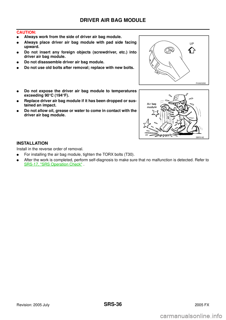
CAUTION:
�Always work from the side of driver air bag module.
�Always place driver air bag module with pad side facing
upward.
�Do not insert any foreign objects (screwdriver, etc.) into
driver air bag module.
�Do not disassemble driver air bag module.
�Do not use old bolts after removal; replace with new bolts.
�Do not expose the driver air bag module to temperatures
exceeding 90 °C (194 °F).
�Replace driver air bag module if it has been dropped or sus-
tained an impact.
�Do not allow oil, grease or water to come in contact with the
driver air bag module.
INSTALLATION
Install in the reverse order of removal.
�For installing the air bag module, tighten the TORX bolts (T30).
�After the work is completed, perform self-diagnosis to make sure that no malfunction is detected. Refer to
SRS-17, "
SRS Operation Check" .
PHIA0320E
SBF814E
Page 4622 of 4731

FRONT PASSENGER AIR BAG MODULE SRS-39
C
D E
F
G
I
J
K L
M A
B
SRS
Revision: 2005 July 2005 FX
FRONT PASSENGER AIR BAG MODULEPFP:K8515
Removal and InstallationAHS000HY
REMOVAL
CAUTION:
�Before servicing SRS, turn ignition switch OFF, disconnect both battery cables and wait at least 3
minutes.
�Always work from the side of or under front passenger air bag module.
1. Remove glove box assembly and instrument passenger lower panel. Refer to IP-13, "
(J) Instrument Pas-
senger Lower Panel" .
2. Remove display control unit, if navigation system is equipped.
3. Remove tire pressure warning control unit, if tire pressure warning control system is equipped.
4. Disconnect front passenger air bag module connector.
5. Remove the front passenger air bag module fixing nuts and bolt, then remove front passenger air bag module.
CAUTION:
�Always place front passenger air bag module with caution
label side facing upward.
�Do not insert any foreign objects (screwdriver, etc.) into
front passenger air bag module.
�Do not disassemble front passenger air bag module.
�Do not use old bolts after removal; replace with new bolts.
�Replace front passenger air bag module if it has been
dropped or sustained an impact.
�Do not expose the front passenger air bag module to tem-
peratures exceeding 90 °C (194 °F).
�Do not allow oil, grease or water to come in contact with the
front passenger air bag module.
�After front passenger air bag module inflates, the instru-
ment panel assembly should be replaced.
INSTALLATION
Install in the reverse order of removal.
CAUTION:
�Always work from the side of or under front passenger air bag module.
�After the work is completed, perform self-diagnosis to make sure no malfunction is detected.
Refer to SRS-17, "
SRS Operation Check" .
PHIA0322E
PHIA0325E
SBF814E
Page 4623 of 4731

SRS-40
SIDE CURTAIN AIR BAG MODULE
Revision: 2005 July 2005 FX
SIDE CURTAIN AIR BAG MODULEPFP:985P0
Removal and InstallationAHS000I0
REMOVAL
CAUTION:
�Before servicing SRS, turn ignition switch OFF, disconnect both battery cables and wait at least 3
minutes.
�Always work from the side of the side curtain air bag module.
1. Remove headlining. Refer to EI-41, "
Removal and Installation" .
2. Disconnect side curtain air bag connector.
3. Remove side curtain air bag module fixing bolts, and remove the side curtain air bag module.
CAUTION:
�Always place the side curtain air bag module with the warn-
ing label facing upward.
�Do not disassemble side curtain air bag module.
�Do not insert any foreign objects (screwdriver, etc.) into air
bag module connector.
�Replace side curtain air bag module if it has been dropped
or sustained an impact.
�Do not expose the air bag module to temperatures exceed-
ing 90 °C (194 °F).
�Do not allow oil, grease or water to come in contact with the
side curtain air bag module.
1. Side curtain air bag Inflator 2. Side curtain air bag 3. Bolt
4. Assist grip bracket 5. Bolt (There is no torque control)
PHIA0656E
PHIA0317E
SBF814E
Page 4635 of 4731

TF-2Revision: 2005 July 2005 FX
Started .................................................................
... 35
DIAGNOSTIC PROCEDURE ........................... ... 35
Vehicle Does Not Enter AWD Mode Even Though
AWD Warning Lamp Turned to OFF .................... ... 36
DIAGNOSTIC PROCEDURE ........................... ... 36
While Driving, AWD Warning Lamp Flashes Rapidly
(When Flashing in Approx. 1 Minute and Then Turn-
ing OFF) .............................................................. ... 37
While Driving, AWD Warning Lamp Flashes Slowly
(When Continuing to Flash until Turning Ignition
Switch OFF) ......................................................... ... 37
DIAGNOSTIC PROCEDURE ........................... ... 37
AWD CONTROL UNIT ........................................... ... 39
Removal and Installation ..................................... ... 39
REMOVAL ........................................................ ... 39
INSTALLATION ................................................. ... 39
FRONT OIL SEAL .................................................. ... 40
Removal and Installation ..................................... ... 40
REMOVAL ........................................................ ... 40
INSTALLATION ................................................. ... 40 REAR OIL SEAL ....................................................
... 41
Removal and Installation ...................................... ... 41
REMOVAL ......................................................... ... 41
INSTALLATION ................................................. ... 42
AIR BREATHER HOSE .......................................... ... 43
Removal and Installation ...................................... ... 43
TRANSFER ASSEMBLY ........................................ ... 44
Removal and Installation ...................................... ... 44
REMOVAL ......................................................... ... 44
INSTALLATION ................................................. ... 44
Disassembly and Assembly ................................. ... 45
COMPONENTS ................................................ ... 45
DISASSEMBLY ................................................. ... 46
INSPECTION .................................................... ... 51
ASSEMBLY ....................................................... ... 52
SERVICE DATA AND SPECIFICATIONS (SDS) ... ... 59
General Specifications ......................................... ... 59
Page 4638 of 4731

PREPARATION TF-5
C E F
G H
I
J
K L
M A
B
TF
Revision: 2005 July 2005 FX
PREPARATIONPFP:00002
Special Service ToolsADS000RL
The actual shapes of Kent-Moore tools may differ from those of special service tools illustrated here.
Tool number
(Kent-Moore No.)
Tool name Description
ST27862000
(—)
Drift
a: 62.5 mm (2.461 in) dia.
b: 42 mm (1.65 in) dia.
�Installing front oil seal
KV381054S0
(J-34286)
Puller
�Removing rear oil seal
ST30720000
(J-25405)
Drift
a: 77 mm (3.03 in) dia.
b: 55.5 mm (2.185 in) dia.
�Installing rear oil seal
�Installing mainshaft oil seal
KV40104830
(—)
Drift
a: 70 mm (2.76 in) dia.
b: 63.5 mm (2.500 in) dia.
�Installing rear oil seal
KV38100300
(J-25523)
Drift
a: 54 mm (2.13 in) dia.
b: 46 mm (1.81 in) dia.
c: 32 mm (1.26 in) dia.
�Removing mainshaft bearing
ST33052000
(—)
Drift
a: 28 mm (1.10 in) dia.
b: 22 mm (0.87 in) dia.
�Removing mainshaft assembly
ST30611000
(J-25742-1)
Drift bar
a: 350 mm (1.10 in)
b: 25 mm (1.10 in) dia.
c: M12 × 1.5P
�Removing rear bearing
ZZA0194D
ZZA0601D
ZZA0811D
ZZA1003D
ZZA1046D
ZZA1000D
NT663
Page 4641 of 4731
TF-8
NOISE, VIBRATION AND HARSHNESS (NVH) TROUBLESHOOTING
Revision: 2005 July 2005 FX
NOISE, VIBRATION AND HARSHNESS (NVH) TROUBLESHOOTINGPFP:00003
NVH Troubleshooting ChartADS000RM
Use the chart below to help you find the cause of the symptom. The numbers indicate the order of the inspec-
tion. If necessary, repair or replace these parts.
Reference pageTF-9TF-45TF-45TF-51TF-51TF-51
SUSPECTED PARTS
(Possible cause)
TRANSFER FLUID (Level low)
TRANSFER FLUID (Wrong)
TRANSFER FLUID (Level too high)
LIQUID GASKET (Damaged)
OIL SEAL (Worn or damaged)
GEAR (Worn or damaged)
BEARING (Worn or damaged)
TRANSFER CASE (Damaged)
Symptom Noise 1 2 3 3 3
Transfer fluid leakage 4 1 2 2 3
Page 4673 of 4731
TF-40
FRONT OIL SEAL
Revision: 2005 July 2005 FX
FRONT OIL SEALPFP:38189
Removal and InstallationADS000RP
REMOVAL
1. Remove the drain plug to drain the transfer fluid. Refer to TF-9, "Replacement" .
2. Remove the front propeller shaft. Refer to PR-4, "
FRONT PROPELLER SHAFT" .
3. Remove front oil seal using a flat-bladed screwdriver. CAUTION:
Be careful not to damage the front case and front drive
shaft.
INSTALLATION
1. Apply ATF to front oil seal, install it with a drift until the end face of front case.
CAUTION:
�Do not reuse front oil seal.
�When installing, do not incline front oil seal.
2. Install front propeller shaft. Refer to PR-4, "
FRONT PROPEL-
LER SHAFT" .
3. Install transfer fluid, check fluid level and for fluid leakage. Refer to TF-9, "
Inspection" .
SDIA1782E
Tool number : ST27862000 ( — )
SDIA1783E
 TROUBLESHOOTING
Revision: 2005 July 2005 FX
NOISE, VIBRATION AND HARSHNESS (NVH) TROUBLESHOOTINGPFP:00003
NVH Troubleshooting ChartADS000RM
Use the chart belo")
