Page 3001 of 4731
![INFINITI FX35 2005 Service Manual EM-166
[VK45DE]
PREPARATION
Revision: 2005 July 2005 FX
PREPARATIONPFP:00002
Special Service ToolsABS006I2
The actual shapes of Kent-Moore tools may differ from those of special service tools illustra](/manual-img/42/57020/w960_57020-3000.png "INFINITI FX35 2005 Service Manual EM-166
[VK45DE]
PREPARATION
Revision: 2005 July 2005 FX
PREPARATIONPFP:00002
Special Service ToolsABS006I2
The actual shapes of Kent-Moore tools may differ from those of special service tools illustra")
EM-166
[VK45DE]
PREPARATION
Revision: 2005 July 2005 FX
PREPARATIONPFP:00002
Special Service ToolsABS006I2
The actual shapes of Kent-Moore tools may differ from those of special service tools illustrated here.
Tool number
(Kent-Moore No.)
Tool name Description
KV10111100
(J–37228)
Seal cutter Removing steel oil pan and front cover
KV10114400
(J-38365)
Heated oxygen sensor wrench Loosening or tightening heated oxygen
sensors
a: 22 mm (0.87 in)
EG15050500
(J–45402)
Compression gauge adapter Inspection of compression pressure
KV10116200
(J–26336-A)
Valve spring compressor
1. KV10115900
(J–26336-20)
Attachment
2. KV10109220
(—)
Adapter Disassembling valve mechanism
Part (1) is a component of KV10116200
(J26336-A), but part (2) is not so.
KV101151S0
(J–38972)
Lifter stopper set
1. KV10115110
(J–38972-1)
Camshaft pliers
2. KV10115120
(J–38972-2)
Lifter stopper Changing valve lifter shims
KV10112100
(BT8653-A)
Angle wrench Tightening bolts for bearing cap, cylinder
head, etc.
S-NT046
S-NT636
ZZA1225D
PBIC1650E
S-NT041
S-NT014
Page 3003 of 4731
EM-168
[VK45DE]
PREPARATION
Revision: 2005 July 2005 FX
Commercial Service ToolsABS006I3
—
(J-45476)
Ring gear stopper Removing and installing crankshaft pulley
—
(J-45488)
Quick connector release Removing fuel tube quick connectors in
engine room
Tool number
(Kent-Moore No.)
Tool name Description
PBIC1655E
PBIC0198E
(Kent-Moore No.)
Tool name Description
(—)
Power tool Loosening nuts and bolts
(—)
Spark plug wrench Removing and installing spark plug
(—)
Manual lift table caddy Removing and installing engine
(J–24239-01)
Cylinder head bolt wrench Loosening and tightening cylinder head bolt,
and use with angle wrench [SST:
KV10112100 (BT–8653-A)]
a: 13 (0.51) dia.
b: 12 (0.47)
c: 10 (0.39)
Unit: mm (in)
PBIC0190E
S-NT047
ZZA1210D
NT583
Page 3013 of 4731
EM-178
[VK45DE]
INTAKE MANIFOLD
Revision: 2005 July 2005 FX
INTAKE MANIFOLDPFP:14003
ComponentsABS00DFO
1. PCV tube 2. Engine cover rear bracket 3. EVAP canister purge control sole-
noid valve
4. EVAP hose 5. EVAP tube 6. EVAP hose
7. Vacuum gallery 8. Engine cover front bracket 9. Vacuum tank
10. VIAS control solenoid valve 11. Water gallery 12. Gasket
13. Intake manifold (lower) 14. Gasket 15. Water hose
16. Intake manifold adapter 17. Electric throttle control actuator 18. Gasket
19. Intake manifold (upper) 20. Resonator 21. EVAP service port
PBIC2755E
Page 3019 of 4731
![INFINITI FX35 2005 Service Manual EM-184
[VK45DE]
EXHAUST MANIFOLD AND THREE WAY CATALYST
Revision: 2005 July 2005 FX
INSPECTION AFTER REMOVAL
Surface Distortion
�Check the surface distortion of the each exhaust manifold flange
mati](/manual-img/42/57020/w960_57020-3018.png "INFINITI FX35 2005 Service Manual EM-184
[VK45DE]
EXHAUST MANIFOLD AND THREE WAY CATALYST
Revision: 2005 July 2005 FX
INSPECTION AFTER REMOVAL
Surface Distortion
�Check the surface distortion of the each exhaust manifold flange
mati")
EM-184
[VK45DE]
EXHAUST MANIFOLD AND THREE WAY CATALYST
Revision: 2005 July 2005 FX
INSPECTION AFTER REMOVAL
Surface Distortion
�Check the surface distortion of the each exhaust manifold flange
mating surface with straightedge and feeler gauge.
�If it exceeds the limit, replace exhaust manifold.
INSTALLATION
Note the following, and install in the reverse order of removal.
Exhaust Manifold Gasket
Install exhaust manifold gasket with its directional protrusion set upward.
Refer to the figure of components on former page. Refer to EM-182, "
Removal and Installation" .
Exhaust Manifold
�Install exhaust manifold and tighten mounting nuts in numerical
order as shown in the figure.
NOTE:
Tighten mounting nuts No. 1 to 4 in two steps. The numerical
order No. 9 to 12 shown second steps.
Heated Oxygen Sensor
�Install heated oxygen sensors in the original position.
�Install referring the following if the installation positions cannot
be identified.
*: The length of glass tube of bank 2 is longer than the one
of bank 1.
CAUTION:
�Before installing a new heated oxygen sensor, clean
exhaust system threads using oxygen sensor thread
cleaner (commercial service tool: J-43897-18 or J-43897-12), and apply anti-seize lubricant (com-
mercial service tool).
�Do not over torque heated oxygen sensor. Doing so may cause damage to the heated oxygen sen-
sor, resulting in “MIL” coming on. Limit : 0.3 mm (0.012 in)
PBIC1550E
PBIC1549E
Glass tube color
Heated oxygen sensor 1* : Black
Heated oxygen sensor 2 : White
PBIC2652E
Page 3025 of 4731
![INFINITI FX35 2005 Service Manual EM-190
[VK45DE]
SPARK PLUG (PLATINUM-TIPPED TYPE)
Revision: 2005 July 2005 FX
SPARK PLUG (PLATINUM-TIPPED TYPE)PFP:22401
ComponentsABS00DFS
Removal and InstallationABS006IG
REMOVAL
1. Remove engine c](/manual-img/42/57020/w960_57020-3024.png "INFINITI FX35 2005 Service Manual EM-190
[VK45DE]
SPARK PLUG (PLATINUM-TIPPED TYPE)
Revision: 2005 July 2005 FX
SPARK PLUG (PLATINUM-TIPPED TYPE)PFP:22401
ComponentsABS00DFS
Removal and InstallationABS006IG
REMOVAL
1. Remove engine c")
EM-190
[VK45DE]
SPARK PLUG (PLATINUM-TIPPED TYPE)
Revision: 2005 July 2005 FX
SPARK PLUG (PLATINUM-TIPPED TYPE)PFP:22401
ComponentsABS00DFS
Removal and InstallationABS006IG
REMOVAL
1. Remove engine cover with power tool. Refer to EM-172, "ENGINE ROOM COVER" .
2. Remove ignition coil. Refer to EM-189, "
IGNITION COIL" .
3. Remove spark plug with spark plug wrench (commercial service tool).
CAUTION:
Do not drop or shock it.
INSPECTION AFTER REMOVAL
Use standard type spark plug for normal condition.
Hot type spark plug is suitable when fouling occurs with standard type spark plug under conditions such as:
�Frequent engine starts
�Low ambient temperatures
Cold type spark plug is suitable when spark plug knock occurs with standard type spark plug under conditions
such as:
�Extended highway driving
�Frequent high engine revolution
1. Ignition coil 2. Spark plug
PBIC1589E
SEM294A
Make NGK
Standard type PLFR5A-11
Hot type PLFR4A-11
Cold type PLFR6A-11
Gap (Nominal) : 1.1 mm (0.043 in)
Page 3043 of 4731
![INFINITI FX35 2005 Service Manual EM-208
[VK45DE]
TIMING CHAIN
Revision: 2005 July 2005 FX
7. Install oil pump drive spacer as follows:
a. Insert oil pump drive spacer according to the directions of crank- shaft key and the two flat](/manual-img/42/57020/w960_57020-3042.png "INFINITI FX35 2005 Service Manual EM-208
[VK45DE]
TIMING CHAIN
Revision: 2005 July 2005 FX
7. Install oil pump drive spacer as follows:
a. Insert oil pump drive spacer according to the directions of crank- shaft key and the two flat")
EM-208
[VK45DE]
TIMING CHAIN
Revision: 2005 July 2005 FX
7. Install oil pump drive spacer as follows:
a. Insert oil pump drive spacer according to the directions of crank- shaft key and the two flat surfaces of oil pump inner rotor.
�If the positional relationship does not allow the insertion,
rotate oil pump inner rotor with a finger to allow spacer.
b. After confirming that the position of each part is in correct condi- tion to allow for spacer, force fit spacer by lightly tapping with
plastic hammer until it contacts and does not go further.
8. Install front oil seal on front cover.
�Apply new engine oil to both oil seal lip and dust seal lip.
�Install it so that each seal lip is oriented as shown in the fig-
ure.
CAUTION:
Be careful not to scratch or make burrs on circumference
of oil seal.
�Using front oil seal drift (commercial service tool), press fit
until the height of front oil seal is level with the mounting sur-
face.
�Make sure the garter spring is in position and seal lips not
inverted.
9. Install chain tensioner cover to front cover.
�Apply a continuous bead of liquid gasket with tube presser
[SST: WS39930000 ( — )] to front cover as shown in the
figure.
Use Genuine RTV Silicone Sealant or equivalent. Refer to
GI-48, "
RECOMMENDED CHEMICAL PRODUCTS AND
SEALANTS" .
10. Install front cover as follows:
PBIC0058E
SEM715A
Front oil seal drift Outer diameter : 56 mm (2.20 in)
Inner diameter : 49 mm (1.93 in)
PBIC0059E
SBIA0372E
Page 3063 of 4731
EM-228
[VK45DE]
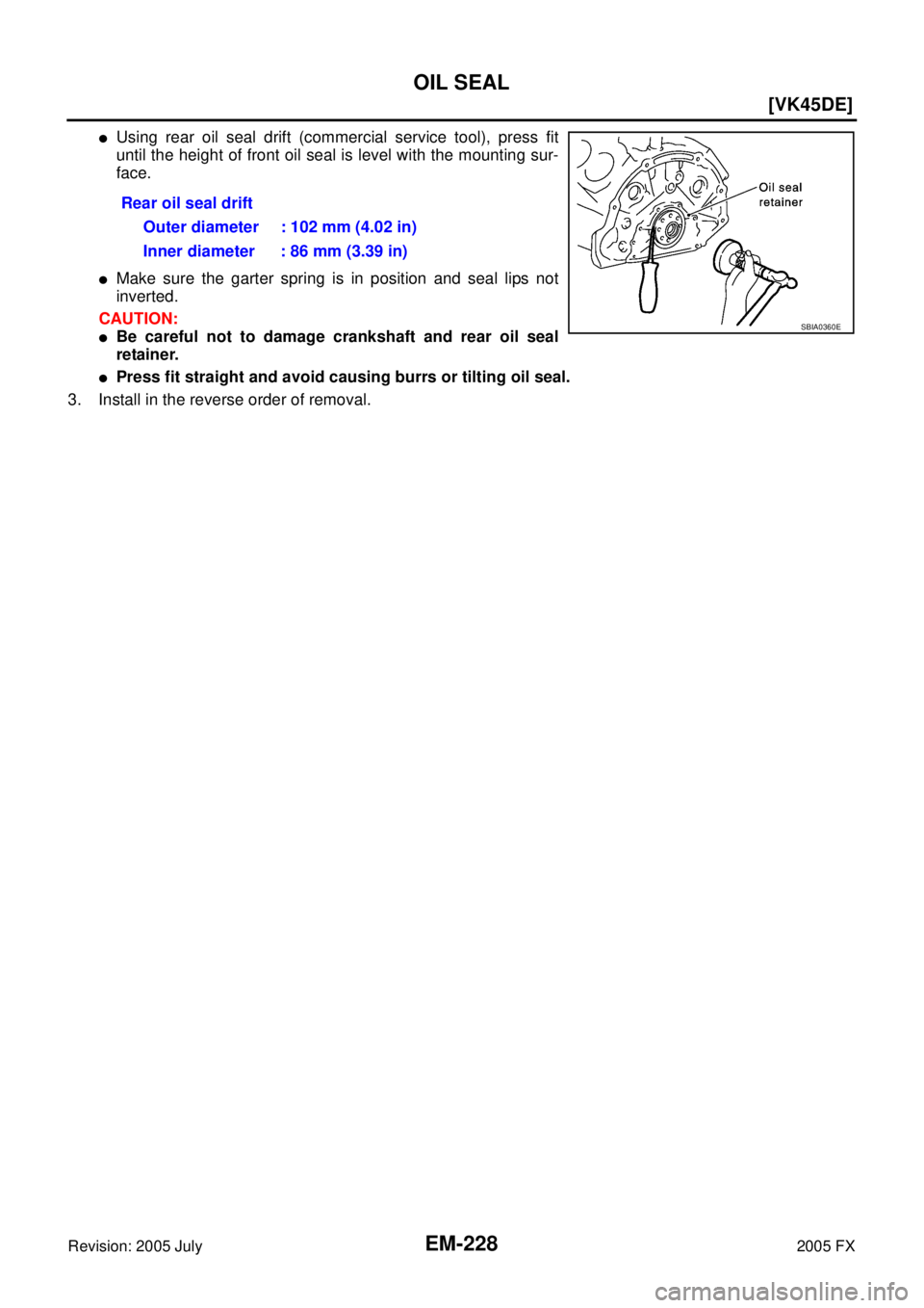
OIL SEAL
Revision: 2005 July 2005 FX
�Using rear oil seal drift (commercial service tool), press fit
until the height of front oil seal is level with the mounting sur-
face.
�Make sure the garter spring is in position and seal lips not
inverted.
CAUTION:
�Be careful not to damage crankshaft and rear oil seal
retainer.
�Press fit straight and avoid causing burrs or tilting oil seal.
3. Install in the reverse order of removal. Rear oil seal drift
Outer diameter : 102 mm (4.02 in)
Inner diameter : 86 mm (3.39 in)
SBIA0360E
Page 3064 of 4731
![INFINITI FX35 2005 Service Manual CYLINDER HEAD EM-229
[VK45DE]
C
D E
F
G H
I
J
K L
M A
EM
Revision: 2005 July 2005 FX
CYLINDER HEADPFP:11041
On-Vehicle ServiceABS006IP
CHECKING COMPRESSION PRESSURE
1. Warm up engine thor](/manual-img/42/57020/w960_57020-3063.png "INFINITI FX35 2005 Service Manual CYLINDER HEAD EM-229
[VK45DE]
C
D E
F
G H
I
J
K L
M A
EM
Revision: 2005 July 2005 FX
CYLINDER HEADPFP:11041
On-Vehicle ServiceABS006IP
CHECKING COMPRESSION PRESSURE
1. Warm up engine thor")
CYLINDER HEAD EM-229
[VK45DE]
C
D E
F
G H
I
J
K L
M A
EM
Revision: 2005 July 2005 FX
CYLINDER HEADPFP:11041
On-Vehicle ServiceABS006IP
CHECKING COMPRESSION PRESSURE
1. Warm up engine thoroughly. Then, stop it.
2. Release fuel pressure. Refer to EC-789, "
FUEL PRESSURE RELEASE" .
a. Remove fuel pump fuse to avoid fuel injection during measure- ment.
3. Remove engine cover with power tool. Refer to EM-172, "
ENGINE ROOM COVER" .
4. Remove ignition coil and spark plug from each cylinder. Refer to EM-189, "
IGNITION COIL" and EM-190,
"SPARK PLUG (PLATINUM-TIPPED TYPE)" .
5. Connect engine tachometer (not required in use of CONSULT-II).
6. Install compression gauge with adapter (SST or commercial ser- vice tool) onto spark plug hole.
�Use compression gauge adapter (SST) which is required on
No. 7 and 8 cylinders.
�Use compression gauge adapter (if no SST is used) whose
picking up end inserted to spark plug hole is smaller than 20
mm (0.79 in) in diameter. Otherwise, it may be caught by cyl-
inder head during removal.
7. With accelerator pedal fully depressed, turn ignition switch to “START” for cranking. When the gauge pointer stabilizes, read the compression pressure and engine rpm. Perform these steps to check each cyl-
inder.
Compression pressure:
Unit: kPa (kg/cm2 , psi) /rpm
CAUTION:
Always use a fully changed battery to obtain the specified engine speed.
PBIB1482E
PBIC1554E
SBIA0533E
Standard Minimum Deferential limit between cylinders
1,320 (13.5, 191) / 300 1,130 (11.5, 164) / 300 98 (1.0, 14) / 300
![INFINITI FX35 2005 Service Manual EM-168
[VK45DE]
PREPARATION
Revision: 2005 July 2005 FX
Commercial Service ToolsABS006I3
—
(J-45476)
Ring gear stopper Removing and installing crankshaft pulley
—
(J-45488)
Quick connector re](/manual-img/42/57020/w960_57020-3002.png "INFINITI FX35 2005 Service Manual EM-168
[VK45DE]
PREPARATION
Revision: 2005 July 2005 FX
Commercial Service ToolsABS006I3
—
(J-45476)
Ring gear stopper Removing and installing crankshaft pulley
—
(J-45488)
Quick connector re")
![INFINITI FX35 2005 Service Manual EM-178
[VK45DE]
INTAKE MANIFOLD
Revision: 2005 July 2005 FX
INTAKE MANIFOLDPFP:14003
ComponentsABS00DFO
1. PCV tube 2. Engine cover rear bracket 3. EVAP canister purge control sole-
noid valve
4. EV](/manual-img/42/57020/w960_57020-3012.png "INFINITI FX35 2005 Service Manual EM-178
[VK45DE]
INTAKE MANIFOLD
Revision: 2005 July 2005 FX
INTAKE MANIFOLDPFP:14003
ComponentsABS00DFO
1. PCV tube 2. Engine cover rear bracket 3. EVAP canister purge control sole-
noid valve
4. EV")