Page 1219 of 4731
![INFINITI FX35 2005 Service Manual CO-14
[VQ35DE]
RADIATOR
Revision: 2005 July 2005 FX
RADIATORPFP:21400
ComponentsABS00E7X
Removal and InstallationABS004WE
REMOVAL
WARNING:
Do not remove radiator cap when engine is hot. Serious burns](/manual-img/42/57020/w960_57020-1218.png "INFINITI FX35 2005 Service Manual CO-14
[VQ35DE]
RADIATOR
Revision: 2005 July 2005 FX
RADIATORPFP:21400
ComponentsABS00E7X
Removal and InstallationABS004WE
REMOVAL
WARNING:
Do not remove radiator cap when engine is hot. Serious burns")
CO-14
[VQ35DE]
RADIATOR
Revision: 2005 July 2005 FX
RADIATORPFP:21400
ComponentsABS00E7X
Removal and InstallationABS004WE
REMOVAL
WARNING:
Do not remove radiator cap when engine is hot. Serious burns could occur from high-pressure engine
coolant escaping from radiator. Wrap a thick cloth around the cap. Slowly turn it a quarter of a turn to
release built-up pressure. Carefully remove radiator cap by turning it all the way.
1. Remove front engine undercover with power tool.
2. Drain engine coolant from radiator. Refer to CO-11, "
Changing Engine Coolant" .
CAUTION:
�Perform this step when the engine is cold.
�Do not spill engine coolant on drive belts.
3. Remove air duct (inlet) and air cleaner case assembly. Refer to EM-17, "
AIR CLEANER AND AIR DUCT"
.
4. Remove reservoir tank and reservoir tank bracket.
5. Disconnect A/T fluid cooler hoses from radiator.
1. Radiator 2. Radiator upper mount bracket 3. Mounting rubber (upper)
4. Radiator cap 5. Mounting rubber (lower) 6. O-ring
7. Drain plug 8. Clamp (radiator hose) 9. Radiator hose (lower)
10. Radiator hose (upper) 11. Clamp (A/T fluid cooler hose) 12. A/T fluid cooler hose
13. Clamp (reservoir tank hose) 14. Reservoir tank hose 15. Reservoir tank cap
16. Reservoir tank 17. Reservoir tank bracket 18. Radiator cooling fan assembly
SBIA0446E
Page 1220 of 4731
![INFINITI FX35 2005 Service Manual RADIATOR CO-15
[VQ35DE]
C
D E
F
G H
I
J
K L
M A
CO
Revision: 2005 July 2005 FX
�Install blind plug to avoid leakage of A/T fluid.
6. Removal radiator hoses (upper and lower) and reservoi](/manual-img/42/57020/w960_57020-1219.png "INFINITI FX35 2005 Service Manual RADIATOR CO-15
[VQ35DE]
C
D E
F
G H
I
J
K L
M A
CO
Revision: 2005 July 2005 FX
�Install blind plug to avoid leakage of A/T fluid.
6. Removal radiator hoses (upper and lower) and reservoi")
RADIATOR CO-15
[VQ35DE]
C
D E
F
G H
I
J
K L
M A
CO
Revision: 2005 July 2005 FX
�Install blind plug to avoid leakage of A/T fluid.
6. Removal radiator hoses (upper and lower) and reservoir tank hose. CAUTION:
Be careful not to allow engine coolant to contact drive belts.
7. Remove radiator cooling fan assembly. Refer to CO-21, "
COOLING FAN" .
8. Rotate two radiator upper mount brackets 90 degrees in the direction shown in the figure, and remove them.
9. Lift up and remove radiator. CAUTION:
Do not damage or scratch A/C condenser and radiator core
when removing.
INSTALLATION
Installation is the reverse order of removal.
INSPECTION AFTER INSTALLATION
�Check for leaks of engine coolant using the radiator cap tester adapter [SST: EG17650301 (J33984-A)]
and the radiator cap tester (commercial service tool). Refer to CO-11, "
LEAK CHECK" .
�Start and warm up the engine. Visually make sure that there is no leaks of engine coolant and A/T fluid.
Checking Radiator CapABS008FW
�Check valve seat of radiator cap.
–Check if valve seat is swollen to the extent that the edge of the
plunger cannot be seen when watching it vertically from the top.
–Check if valve seat has no soil and damage.
SBIA0447E
SBIA0448E
PBIC2816E
Page 1221 of 4731
![INFINITI FX35 2005 Service Manual CO-16
[VQ35DE]
RADIATOR
Revision: 2005 July 2005 FX
�Pull negative-pressure valve to open it, and make sure that it
close completely when released.
–Make sure that there is no dirt or damage on the](/manual-img/42/57020/w960_57020-1220.png "INFINITI FX35 2005 Service Manual CO-16
[VQ35DE]
RADIATOR
Revision: 2005 July 2005 FX
�Pull negative-pressure valve to open it, and make sure that it
close completely when released.
–Make sure that there is no dirt or damage on the")
CO-16
[VQ35DE]
RADIATOR
Revision: 2005 July 2005 FX
�Pull negative-pressure valve to open it, and make sure that it
close completely when released.
–Make sure that there is no dirt or damage on the valve seat of
radiator cap negative-pressure valve.
–Make sure that there are no unusualness in the opening and
closing conditions of negative-pressure valve.
�Check radiator cap relief pressure.
–When connecting radiator cap to the radiator cap tester (com-
mercial service tool) and the radiator cap tester adapter [SST],
apply engine coolant to the cap seal surface.
�Replace radiator cap if there is an unusualness related to the above three.
CAUTION:
When installing radiator cap, thoroughly wipe out the radiator filler neck to remove any waxy residue
or foreign material.
Checking RadiatorABS008FX
Check radiator for mud or clogging. If necessary, clean radiator as follows.
�Be careful not to bend or damage radiator fins.
�When radiator is cleaned without removal, remove all surrounding parts such as radiator cooling fan
assembly and horns. Then tape harness and connectors to prevent water from entering.
1. Apply water by hose to the back side of the radiator core vertically downward.
2. Apply water again to all radiator core surfaces once per minute.
3. Stop washing if any stains no longer flow out from radiator.
4. Blow air into the back side of radiator core vertically downward.
�Use compressed air lower than 490 kPa (5 kg/cm2 , 71 psi) and keep distance more than 30 cm (11.81
in).
5. Blow air again into all the radiator core surfaces once per minute until no water sprays out.
SMA967B
Standard:
78 - 98 kPa (0.8 - 1.0 kg/cm
2 , 11 - 14 psi)
Limit:
59 kPa (0.6 kg/cm
2 , 9 psi)
SLC755A
Page 1222 of 4731
RADIATOR (ALUMINUM TYPE) CO-17
[VQ35DE]
C
D E
F
G H
I
J
K L
M A
CO
Revision: 2005 July 2005 FX
RADIATOR (ALUMINUM TYPE)PFP:21460
ComponentsABS00E7Y
Disassembly and AssemblyABS004VZ
PREPARATION
1. Attach spacer to tip of the radiator plate pliers A [SST].
Spacer specification: 18 mm (0.71 in) wide × 8.5 mm (0.335 in)
long × 1.5 mm (0.059 in) thick.
2. Make sure that when the radiator plate pliers A [SST: KV99103510 ( — )] are closed dimension H ′′ is
approx. 7.6 mm (0.299 in).
3. Adjust dimension H ′′ with spacer, if necessary.
DISASSEMBLY
1. Remove upper and lower tanks with the radiator plate pliers B
[SST].
CAUTION:
Do not disassemble lower tank and A/T fluid cooler.
NOTE:
Regard lower tank and A/T fluid cooler as an assembly.
1. Upper tank 2. Sealing rubber 3. Core
4. Lower tank (with A/T fluid cooler)
PBIC2539E
SLC655CB
SLC903-A
Page 1223 of 4731
CO-18
[VQ35DE]
RADIATOR (ALUMINUM TYPE)
Revision: 2005 July 2005 FX
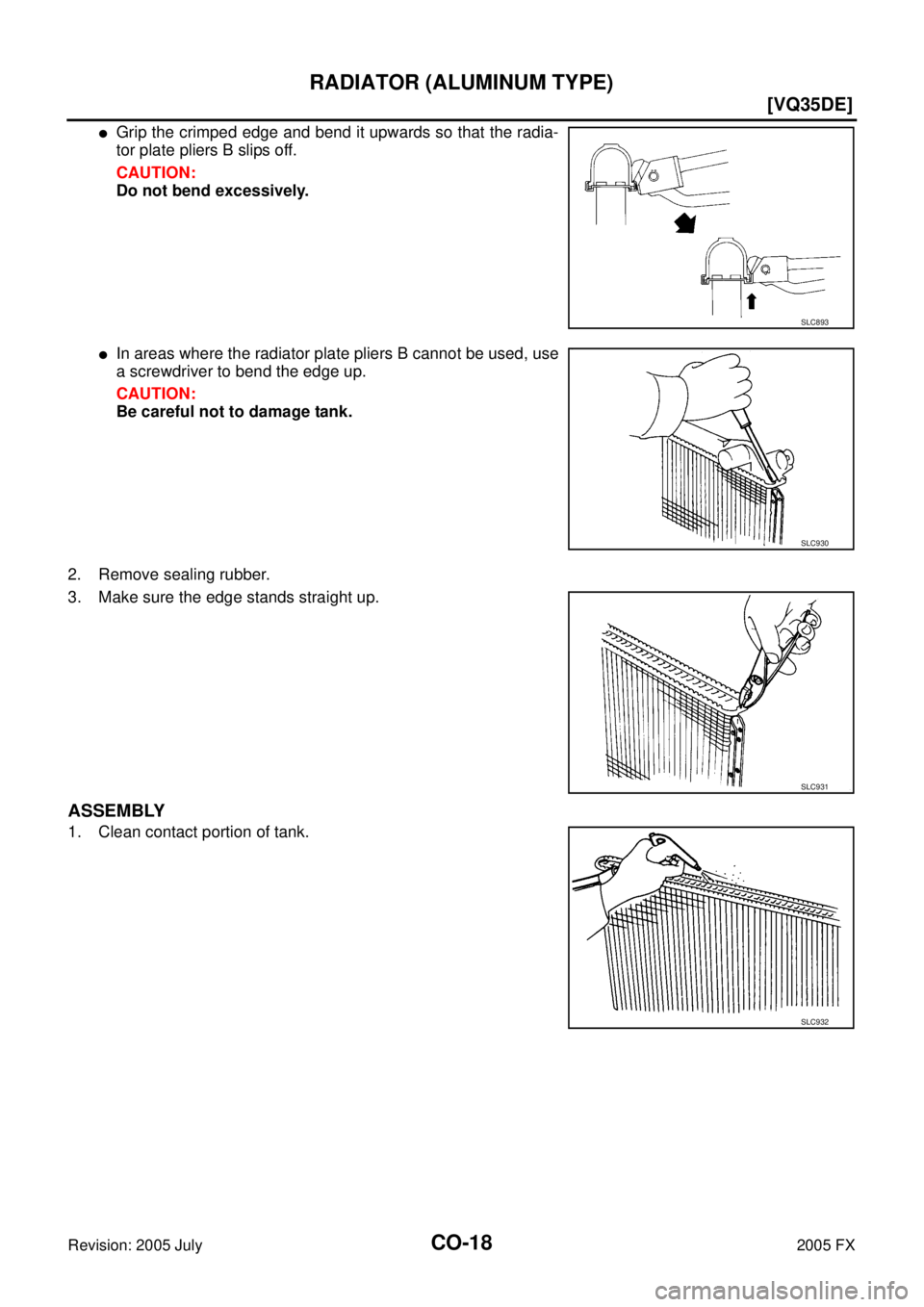
�Grip the crimped edge and bend it upwards so that the radia-
tor plate pliers B slips off.
CAUTION:
Do not bend excessively.
�In areas where the radiator plate pliers B cannot be used, use
a screwdriver to bend the edge up.
CAUTION:
Be careful not to damage tank.
2. Remove sealing rubber.
3. Make sure the edge stands straight up.
ASSEMBLY
1. Clean contact portion of tank.
SLC893
SLC930
SLC931
SLC932
Page 1224 of 4731
RADIATOR (ALUMINUM TYPE) CO-19
[VQ35DE]
C
D E
F
G H
I
J
K L
M A
CO
Revision: 2005 July 2005 FX
2. Install new sealing rubber while pushing it with fingers.
CAUTION:
Be careful not to twist sealing rubber.
3. Caulk tank in numerical order as shown in the figure with the radiator plate pliers A [SST].
�Use pliers in the locations where the radiator plate pliers A
cannot be used.
SLC917A
SLC904-A
PBIC2076E
SLC897
Page 1225 of 4731
CO-20
[VQ35DE]
RADIATOR (ALUMINUM TYPE)
Revision: 2005 July 2005 FX
4. Make sure that the rim is completely crimped down.
5. Make sure that there is no leakage. Refer to CO-20, "
INSPECTION" .
INSPECTION
1. Apply pressure with the radiator cap tester adapter [SST] and
the radiator cap tester (commercial service tool).
WARNING:
To prevent the risk of hose coming undone while under
pressure, securely fasten it down with hose clamp.
CAUTION:
Attach hose to A/T fluid cooler to seal its inlet and outlet. (A/
T models)
2. Check for leakage by soaking radiator in water container with the testing pressure applied. Standard height “H” : 8.0 - 8.4 mm (0.315 - 0.331 in)
SLC554A
Testing pressure
: 157 kPa (1.6 kg/cm
2 , 23
psi)
SLC933-A
SLC934
Page 1226 of 4731
![INFINITI FX35 2005 Service Manual COOLING FAN CO-21
[VQ35DE]
C
D E
F
G H
I
J
K L
M A
CO
Revision: 2005 July 2005 FX
COOLING FANPFP:21140
ComponentsABS00E7Z
Removal and Installation ABS005GR
REMOVAL
1. Remove air duct (inl](/manual-img/42/57020/w960_57020-1225.png "INFINITI FX35 2005 Service Manual COOLING FAN CO-21
[VQ35DE]
C
D E
F
G H
I
J
K L
M A
CO
Revision: 2005 July 2005 FX
COOLING FANPFP:21140
ComponentsABS00E7Z
Removal and Installation ABS005GR
REMOVAL
1. Remove air duct (inl")
COOLING FAN CO-21
[VQ35DE]
C
D E
F
G H
I
J
K L
M A
CO
Revision: 2005 July 2005 FX
COOLING FANPFP:21140
ComponentsABS00E7Z
Removal and Installation ABS005GR
REMOVAL
1. Remove air duct (inlet), power duct and air cleaner case assembly. Refer to EM-17, "AIR CLEANER AND
AIR DUCT" .
2. Disconnect harness connector from fan motors, and move harness to aside.
3. Remove radiator cooling fan assembly.
CAUTION:
Be careful not to damage or scratch on radiator core.
INSTALLATION
Installation is the reverse order of removal.
INSPECTION AFTER INSTALLATION
Make sure that fan motors operate normally.
NOTE:
Cooling fans are controlled by ECM. For details, refer to EC-467, "
DTC P1217 ENGINE OVER TEMPERA-
TURE" .
Disassembly and Assembly ABS004WG
DISASSEMBLY
1. Remove cooling fans (RH and LH) from fan motors.
2. Remove fan motors from fan shroud.
INSPECTION AFTER DISASSEMBLY
Cooling Fan
Inspect cooling fan for crack or unusual bend.
�If anything is found, replace cooling fan.
ASSEMBLY
Assemble in the reverse order of disassembly.
CAUTION:
Cooling fans and fan motors are different between RH and LH. Be careful not to misassemble them.
1. Cooling fan (RH) 2. Cooling fan (LH) 3. Fan shroud
4. Fan motor
PBIC3047E
![INFINITI FX35 2005 Service Manual RADIATOR (ALUMINUM TYPE) CO-17
[VQ35DE]
C
D E
F
G H
I
J
K L
M A
CO
Revision: 2005 July 2005 FX
RADIATOR (ALUMINUM TYPE)PFP:21460
ComponentsABS00E7Y
Disassembly and AssemblyABS004VZ
PREPAR](/manual-img/42/57020/w960_57020-1221.png "INFINITI FX35 2005 Service Manual RADIATOR (ALUMINUM TYPE) CO-17
[VQ35DE]
C
D E
F
G H
I
J
K L
M A
CO
Revision: 2005 July 2005 FX
RADIATOR (ALUMINUM TYPE)PFP:21460
ComponentsABS00E7Y
Disassembly and AssemblyABS004VZ
PREPAR")
![INFINITI FX35 2005 Service Manual RADIATOR (ALUMINUM TYPE) CO-19
[VQ35DE]
C
D E
F
G H
I
J
K L
M A
CO
Revision: 2005 July 2005 FX
2. Install new sealing rubber while pushing it with fingers.
CAUTION:
Be careful not to tw](/manual-img/42/57020/w960_57020-1223.png "INFINITI FX35 2005 Service Manual RADIATOR (ALUMINUM TYPE) CO-19
[VQ35DE]
C
D E
F
G H
I
J
K L
M A
CO
Revision: 2005 July 2005 FX
2. Install new sealing rubber while pushing it with fingers.
CAUTION:
Be careful not to tw")
![INFINITI FX35 2005 Service Manual CO-20
[VQ35DE]
RADIATOR (ALUMINUM TYPE)
Revision: 2005 July 2005 FX
4. Make sure that the rim is completely crimped down.
5. Make sure that there is no leakage. Refer to CO-20, "
INSPECTION" .
INS](/manual-img/42/57020/w960_57020-1224.png "INFINITI FX35 2005 Service Manual CO-20
[VQ35DE]
RADIATOR (ALUMINUM TYPE)
Revision: 2005 July 2005 FX
4. Make sure that the rim is completely crimped down.
5. Make sure that there is no leakage. Refer to CO-20, \"
INSPECTION\" .
INS")