Page 4646 of 4731
 is a ser")
AWD SYSTEM TF-13
C E F
G H
I
J
K L
M A
B
TF
Revision: 2005 July 2005 FX
COMPONENTS FUNCTION DESCRIPTION
CAN CommunicationADS000RY
SYSTEM DESCRIPTION
CAN (Controller Area Network) is a serial communication line for real time application. It is an on-vehicle mul-
tiplex communication line with high data communication speed and excellent error detection ability. Many elec-
tronic control units are equipped onto a vehicle, and each control unit shares information and links with other
control units during operation (not independent). In CAN communication, control units are connected with 2
communication lines (CAN H line, CAN L line) allowing a high rate of information transmission with less wiring.
Each control unit transmits/receives data but selectively reads required data only.
For details, refer to LAN-30, "
CAN Communication Unit" .
Component parts Function
AWD control unit
�Controls driving force distribution by signals from each sensor and switch from rear wheel driving
mode (0:100) to AWD mode (50:50).
�2WD mode is available by fail-safe function if malfunction is detected in AWD system.
Wheel sensors Detects wheel speed.
AWD solenoid Controls electric controlled coupling by command current from AWD control unit.
Electric controlled coupling Transmits driving force to front final drive.
AWD warning lamp
�Illuminates if malfunction is detected in electrical system of AWD system.
�There is 1 blink in 2 seconds if rotation difference of front wheels and rear wheels is large.
�There are 2 blinks in 1 second if load is still applied to driving parts.
ABS actuator and electric unit
(control unit) Transmits the following signals via CAN communication to AWD control unit.
�Vehicle speed signal
�Stop lamp switch signal (brake signal)
ECM Transmits the following signals via CAN communication to AWD control unit.
�Accelerator pedal position signal
�Engine speed signal
Unified meter and A/C amp. Transmits conditions of parking brake switch via CAN communication to AWD control unit.
Page 4677 of 4731

TF-44
TRANSFER ASSEMBLY
Revision: 2005 July 2005 FX
TRANSFER ASSEMBLYPFP:33100
Removal and InstallationADS000RS
REMOVAL
1. Remove tunnel stay with power tool. Refer to RSU-7, "Components" .
2. Remove exhaust front tube with power tool. Refer to EX-3, "
EXHAUST SYSTEM" .
3. Remove front and rear propeller shaft. Refer to PR-4, "
FRONT PROPELLER SHAFT" and PR-7, "REAR
PROPELLER SHAFT" .
4. Disconnect transfer assembly harness connector and separate harness from transfer assembly.
5. Remove air breather hose. Refer to TF-43, "
AIR BREATHER HOSE" .
6. Support transfer assembly and transmission assembly with a jack.
7. Remove engine rear member with power tool. Refer to EM-112, "
ENGINE ASSEMBLY" (VQ35DE) or
EM-240, "
ENGINE ASSEMBLY" (VK45DE).
8. Remove transfer mounting bolts and separate transfer from transmission. CAUTION:
Secure transfer assembly to a jack.
INSTALLATION
Note the following, and install in the reverse order of removal.
�When installing the transfer to the transmission, install the
mounting bolts following the standard below.
�After the installation, check the fluid level and for fluid leakage.
Refer to TF-9, "
Inspection" .
Bolt No. 1 2 3 4
Quantity 4 3 2 1
Bolt length “ ” mm (in) 75 (2.95) 45 (1.77) 40 (1.57) 30 (1.18)
Tightening torque
N·m (kg-m, ft-lb) 37 (3.8, 27)
SDIA2284E
Page 4689 of 4731
TF-56
TRANSFER ASSEMBLY
Revision: 2005 July 2005 FX
16. Apply liquid gasket to mating surface of rear case.
�Use Genuine Anaerobic Liquid Gasket or equivalent.
Refer to GI-48, "
Recommended Chemical Products and
Sealants" .
CAUTION:
Remove old sealant adhering to mounting surfaces. Also
remove any moisture, oil, or foreign material adhering to
application and mounting surfaces.
17. Set front case to rear case. CAUTION:
Be careful not to damage the mating surface transmission
side.
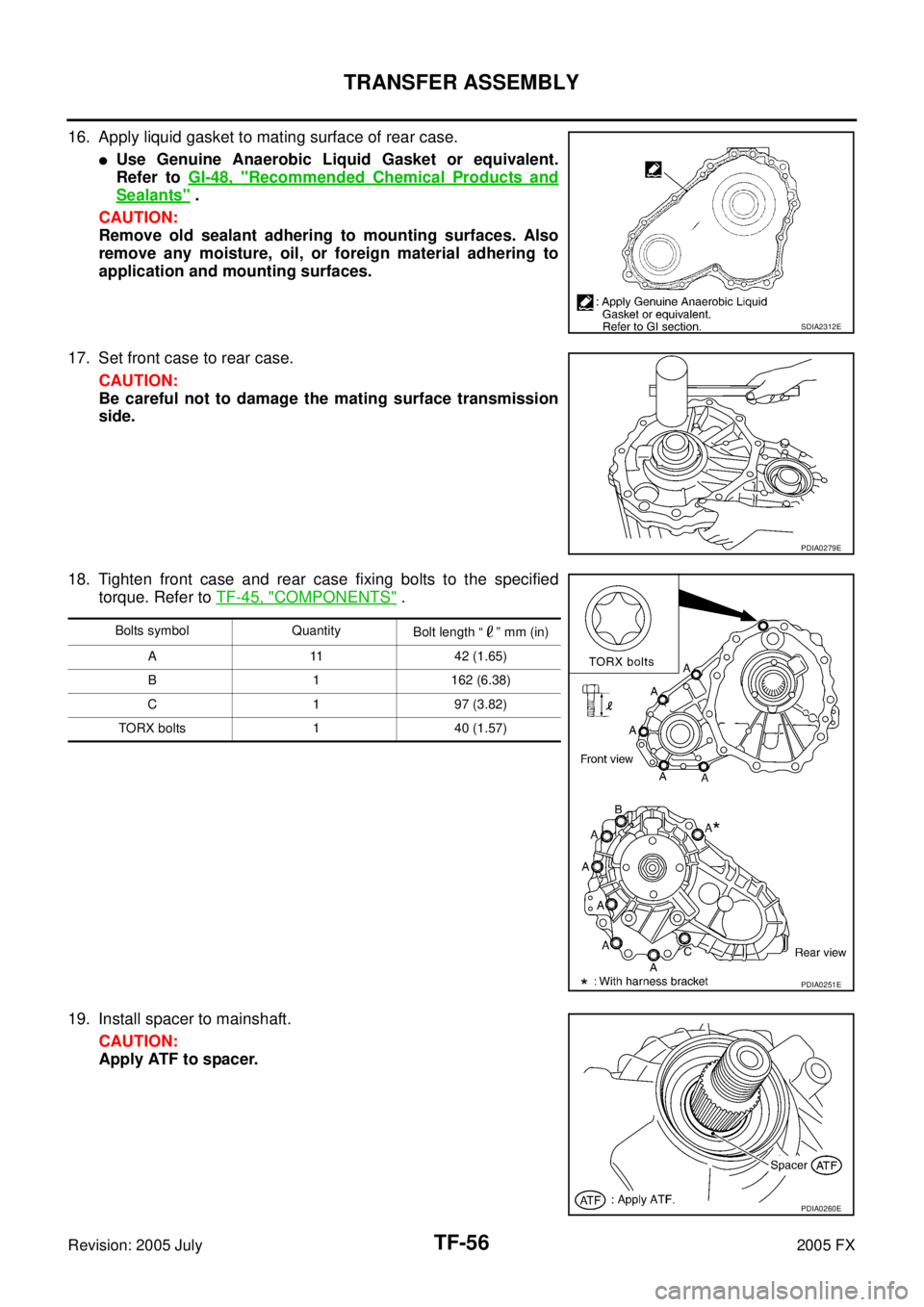
18. Tighten front case and rear case fixing bolts to the specified torque. Refer to TF-45, "
COMPONENTS" .
19. Install spacer to mainshaft. CAUTION:
Apply ATF to spacer.
SDIA2312E
PDIA0279E
Bolts symbol Quantity Bolt length “ ” mm (in)
A 11 42 (1.65)
B 1 162 (6.38)
C 1 97 (3.82)
TORX bolts 1 40 (1.57)
PDIA0251E
PDIA0260E
Page 4702 of 4731
CAN COMMUNICATION WT-9
C
D
F
G H
I
J
K L
M A
B
WT
Revision: 2005 July 2005 FX
CAN COMMUNICATIONPFP:23710
System DescriptionAES000Z1
CAN (Controller Area Network) is a serial communication line for real time application. It is an on-vehicle mul-
tiplex communication line with high data communication speed and excellent error detection ability. Many elec-
tronic control units are equipped onto a vehicle, and each control unit shares information and links with other
control units during operation (not independent). In CAN communication, control units are connected with 2
communication lines (CAN H line, CAN L line) allowing a high rate of information transmission with less wiring.
Each control unit transmits/receives data but selectively reads required data only.
Refer to LAN-30, "
CAN COMMUNICATION" .
 is a serial communication")