2005 INFINITI FX35 trunk
[x] Cancel search: trunkPage 4346 of 4731

SQUEAK AND RATTLE TROUBLE DIAGNOSES RF-7
C
D E
F
G H
J
K L
M A
B
RF
Revision: 2005 July 2005 FX
TRUNK
Trunk noises are often caused by a loose jack or loose items put into the trunk by the owner.
In addition look for:
1. Trunk lid dumpers out of adjustment
2. Trunk lid striker out of adjustment
3. Trunk lid torsion bars knocking together
4. A loose license plate or bracket
Most of these incidents can be repaired by adjusting, securing or insulating the item(s) or component(s) caus-
ing the noise.
SUNROOF/HEADLINING
Noises in the sunroof/headlining area can often be traced to one of the following:
1. Sunroof lid, rail, linkage or seals making a rattle or light knocking noise
2. Sunvisor shaft shaking in the holder
3. Front or rear windshield touching headlining and squeaking
Again, pressing on the components to stop the noise while duplicating the conditions can isolate most of these
incidents. Repairs usually consist of insulating with felt cloth tape.
SEATS
When isolating seat noise it's important to note the position the seat is in and the load placed on the seat when
the noise is present. These conditions should be duplicated when verifying and isolating the cause of the
noise.
Cause of seat noise include:
1. Headrest rods and holder
2. A squeak between the seat pad cushion and frame
3. Rear seatback lock and bracket
These noises can be isolated by moving or pressing on the suspected components while duplicating the con-
ditions under which the noise occurs. Most of these incidents can be repaired by repositioning the component
or applying urethane tape to the contact area.
UNDERHOOD
Some interior noise may be caused by components under the hood or on the engine wall. The noise is then
transmitted into the passenger compartment.
Causes of transmitted underhood noise include:
1. Any component mounted to the engine wall
2. Components that pass through the engine wall
3. Engine wall mounts and connectors
4. Loose radiator mounting pins
5. Hood bumpers out of adjustment
6. Hood striker out of adjustment
These noises can be difficult to isolate since they cannot be reached from the interior of the vehicle. The best
method is to secure, move or insulate one component at a time and test drive the vehicle. Also, engine RPM
or load can be changed to isolate the noise. Repairs can usually be made by moving, adjusting, securing, or
insulating the component causing the noise.
Page 4474 of 4731

SE-1
SEAT
I BODY
CONTENTS
C
D E
F
G H
J
K L
M
SECTION SE
A
B
SE
Revision: 2005 July 2005 FX
SEAT
PRECAUTIONS .......................................................... 3
Precautions for Supplemental Restraint System
(SRS) “AIR BAG” and “SEAT BELT PRE-TEN-
SIONER” ............................................................. ..... 3
Service Notice ..................................................... ..... 3
PREPARATION ...................................................... ..... 4
Special Service Tools .......................................... ..... 4
Commercial Service Tools ................................... ..... 4
SQUEAK AND RATTLE TROUBLE DIAGNOSIS . ..... 5
Work Flow ........................................................... ..... 5
CUSTOMER INTERVIEW ................................ ..... 5
DUPLICATE THE NOISE AND TEST DRIVE .. ..... 6
CHECK RELATED SERVICE BULLETINS ...... ..... 6
LOCATE THE NOISE AND IDENTIFY THE
ROOT CAUSE ................................................. ..... 6
REPAIR THE CAUSE ...................................... ..... 6
CONFIRM THE REPAIR .................................. ..... 7
Generic Squeak and Rattle Troubleshooting ...... ..... 7
INSTRUMENT PANEL ..................................... ..... 7
CENTER CONSOLE ........................................ ..... 7
DOORS ............................................................ ..... 7
TRUNK ............................................................. ..... 8
SUNROOF/HEADLINING ................................ ..... 8
SEATS .............................................................. ..... 8
UNDERHOOD .................................................. ..... 8
Diagnostic Worksheet ......................................... ..... 9
AUTOMATIC DRIVE POSITIONER ....................... ....11
System Description ............................................. .... 11
MANUAL OPERATION .................................... .... 11
AUTOMATIC OPERATION .............................. .... 11
MEMORY STORING AND KEY FOB INTER-
LOCK STORING .............................................. ... 12
MEMORY SWITCH OPERATION .................... ... 13
ENTRY OPERATION ....................................... ... 13
EXITING OPERATION ..................................... ... 13
KEY FOB INTERLOCK OPERATION .............. ... 14
FAIL- SAFE MODE .......................................... ... 14
CANCEL OF FAIL-SAFE MODE ...................... ... 14
Component Parts and Harness Connector Location ... 15
CAN Communication System Description ........... ... 16 CAN Communication Unit ....................................
... 16
Schematic ............................................................ ... 17
Wiring Diagram —AUT/DP— .............................. ... 19
Terminals and Reference Values for BCM ........... ... 30
Terminals and Reference Values for Automatic
Drive Positioner Control Unit ............................... ... 30
Terminals and Reference Values for Driver Seat
Control Unit .......................................................... ... 32
Work Flow ............................................................ ... 35
Preliminary Check ............................................... ... 35
SETTING CHANGE FUNCTION ...................... ... 35
CHECK POWER SUPPLY AND GROUND ...... ... 36
CONSULT-II Function (AUTO DRIVE POS.) ....... ... 38
CONSULT-II INSPECTION PROCEDURE ....... ... 38
SELF-DIAGNOSIS RESULTS .......................... ... 39
DATA MONITOR .............................................. ... 40
ACTIVE TEST .................................................. ... 41
Check CAN Communication System Inspection . ... 42
Symptom Chart .................................................... ... 42
Sliding Motor Circuit Check ................................. ... 43
Reclining Motor Circuit Check ............................. ... 45
Front Lifting Motor Circuit Check ......................... ... 46
Rear Lifting Motor Circuit Check .......................... ... 48
Telescopic Motor Circuit Check ........................... ... 49
Tilt Motor Circuit Check ....................................... ... 50
Driver Side Mirror Motor Circuit Check ................ ... 52
Passenger Side Mirror Motor Circuit Check ........ ... 53
Sliding Sensor Circuit Check ............................... ... 55
Reclining Sensor Circuit Check ........................... ... 56
Front Lifting Sensor Circuit Check ....................... ... 57
Rear Lifting Sensor Circuit Check ....................... ... 58
Telescopic Sensor Circuit Check ......................... ... 59
Tilt Sensor Circuit Check ..................................... ... 60
Driver Side Mirror Sensor Circuit Check .............. ... 61
Passenger Side Mirror Sensor Circuit Check ...... ... 63
Steering and Door Mirror Sensor Power and Ground
Circuit Check ....................................................... ... 65
Front Door Switch (Driver Side) Circuit Check .... ... 66
Sliding Switch Circuit Check ................................ ... 68
Reclining Switch Check ....................................... ... 69
Page 4481 of 4731

SE-8
SQUEAK AND RATTLE TROUBLE DIAGNOSIS
Revision: 2005 July 2005 FX
TRUNK
Trunk noises are often caused by a loose jack or loose items put into the trunk by the owner.
In addition look for:
1. Trunk lid dumpers out of adjustment
2. Trunk lid striker out of adjustment
3. The trunk lid torsion bars knocking together
4. A loose license plate or bracket
Most of these incidents can be repaired by adjusting, securing or insulating the item(s) or component(s) caus-
ing the noise.
SUNROOF/HEADLINING
Noises in the sunroof/headlining area can often be traced to one of the following:
1. Sunroof lid, rail, linkage or seals making a rattle or light knocking noise
2. Sunvisor shaft shaking in the holder
3. Front or rear windshield touching headlining and squeaking
Again, pressing on the components to stop the noise while duplicating the conditions can isolate most of these
incidents. Repairs usually consist of insulating with felt cloth tape.
SEATS
When isolating seat noise it's important to note the position the seat is in and the load placed on the seat when
the noise is present. These conditions should be duplicated when verifying and isolating the cause of the
noise.
Cause of seat noise include:
1. Headrest rods and holder
2. A squeak between the seat pad cushion and frame
3. The rear seatback lock and bracket
These noises can be isolated by moving or pressing on the suspected components while duplicating the con-
ditions under which the noise occurs. Most of these incidents can be repaired by repositioning the component
or applying urethane tape to the contact area.
UNDERHOOD
Some interior noise may be caused by components under the hood or on the engine wall. The noise is then
transmitted into the passenger room.
Causes of transmitted underhood noise include:
1. Any component mounted to the engine wall
2. Components that pass through the engine wall
3. Engine wall mounts and connectors
4. Loose radiator mounting pins
5. Hood bumpers out of adjustment
6. Hood striker out of adjustment
These noises can be difficult to isolate since they cannot be reached from the interior of the vehicle. The best
method is to secure, move or insulate one component at a time and test drive the vehicle. Also, engine RPM
or load can be changed to isolate the noise. Repairs can usually be made by moving, adjusting, securing, or
insulating the component causing the noise.
Page 4580 of 4731

REAR SEAT SE-107
C
D E
F
G H
J
K L
M A
B
SE
Revision: 2005 July 2005 FX
1. Headrest (side) 2. Headrest holder (free) 3. Headrest holder (locked)
4. Seatback trim (RH) 5. Seatback pad (RH) 6. Seatback frame (RH)
7. Nut 8. Seat hinge cover (RH) 9. Screw
10. Reclining lever (RH) 11. Reclining device outer cover (RH) 12. Reclining device inner cover (RH)
13. Bolt 14. Seatback garnish (RH) 15. Trunk net hook
16. Clip (C101) 17. Headrest (center) 18. Seatback trim (LH)
19. Seatback pad (LH) 20. Seatback frame (LH) 21. Seatback garnish (LH)
22. Armrest bracket cover 23. Armrest bracket 24. Armrest
25. Reclining device inner cover (LH) 26. Reclining device outer cover (LH) 27. Reclining lever (LH)
28. Seat hinge cover (LH) 29. Seat cushion trim 30. Seat cushion pad
31. Cup holder bracket 32. Cup holder
Page 4582 of 4731

REAR SEAT SE-109
C
D E
F
G H
J
K L
M A
B
SE
Revision: 2005 July 2005 FX
INSTALLATION OF SEAT CUSHION TRIM AND PAD
Install in the reverse order of removal.
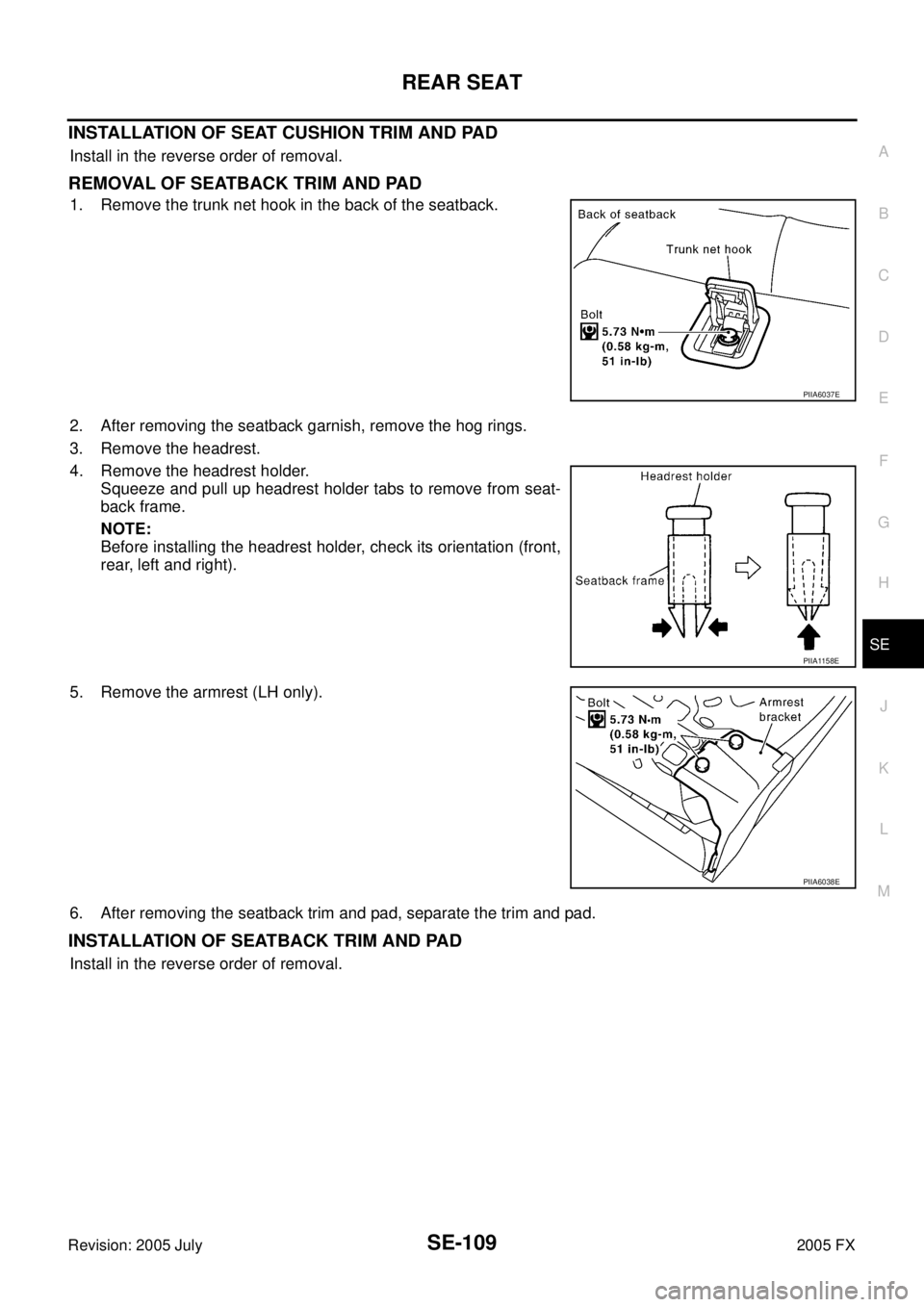
REMOVAL OF SEATBACK TRIM AND PAD
1. Remove the trunk net hook in the back of the seatback.
2. After removing the seatback garnish, remove the hog rings.
3. Remove the headrest.
4. Remove the headrest holder. Squeeze and pull up headrest holder tabs to remove from seat-
back frame.
NOTE:
Before installing the headrest holder, check its orientation (front,
rear, left and right).
5. Remove the armrest (LH only).
6. After removing the seatback trim and pad, separate the trim and pad.
INSTALLATION OF SEATBACK TRIM AND PAD
Install in the reverse order of removal.
PIIA6037E
PIIA1158E
PIIA6038E