Page 318 of 4731

SHIFT CONTROL SYSTEM AT-235
D E
F
G H
I
J
K L
M A
B
AT
Revision: 2005 July 2005 FX
INSTALLATION
Note the following, and install in the reverse order of removal.
�After installation is completed, adjust and check A/T position. Refer to AT- 2 3 5 , "Adjustment of A/T Posi-
tion" and AT- 2 3 5 , "Checking of A/T Position" .
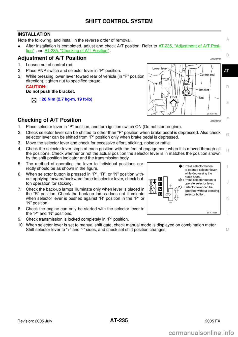
Adjustment of A/T PositionACS002RR
1. Loosen nut of control rod.
2. Place PNP switch and selector lever in “P” position.
3. While pressing lower lever toward rear of vehicle (in “P” position direction), tighten nut to specified torque.
CAUTION:
Do not push the bracket.
Checking of A/T PositionACS002RS
1. Place selector lever in “P” position, and turn ignition switch ON (Do not start engine).
2. Check selector lever can be shifted to other than “P” position when brake pedal is depressed. Also check selector lever can be shifted from “P” position only when brake pedal is depressed.
3. Move the selector lever and check for excessive effort, sticking, noise or rattle.
4. Check the selector lever stops at each position with the feel of engagement when it is moved through all the positions. Check whether or not the actual position the selector lever is in matches the position shown
by the shift position indicator and the transmission body.
5. The method of operating the lever to individual positions cor- rectly should be as shown in the figure.
6. When selector button is pressed in “P”, “R”, or “N” position with- out applying forward/backward force to selector lever, check but-
ton operation for sticking.
7. Check the back-up lamps illuminate only when lever is placed in the “R” position. Check the back-up lamps does not illuminate
when selector lever is pushed against “R” position in the “P” or
“N” position.
8. Check the engine can only be started with the selector lever in the “P” and “N” positions.
9. Check transmission is locked completely in “P” position.
10. When selector lever is set to manual shift gate, check manual mode is displayed on combination meter. Shift selector lever to “+” and “-” sides, and check set shift position changes. : 26 N·m (2.7 kg-m, 19 ft-lb)
SCIA2119E
SCIA7465E
Page 329 of 4731
AT-246
ON-VEHICLE SERVICE
Revision: 2005 July 2005 FX
16. Remove control valve with TCM from transmission case.
CAUTION:
When removing, be careful with the manual valve notch and
manual plate height. Remove it vertically.
17. Remove A/T fluid temperature sensor 2 with bracket from con- trol valve with TCM.
18. Remove bracket from A/T fluid temperature sensor 2.
19. Remove O-ring from A/T assembly harness connector.
20. Disconnect TCM connectors. CAUTION:
Be careful not to damage connectors.
SCIA5142E
SCIA5301E
SCIA5264E
SCIA5155E
SCIA5447E
Page 366 of 4731
OVERHAUL AT-283
D E
F
G H
I
J
K L
M A
B
AT
Revision: 2005 July 2005 FX
7. Pawl shaft 8. Seal ring 9. Needle bearing
10. Revolution sensor 11. Parking gear 12. Output shaft
13. Bearing race 14. Needle bearing 15. Manual plate
16. Parking rod 17. Manual shaft oil seal 18. Manual shaft
19. O-ring 20. Band servo anchor end pin 21. Detent spring
22. Spacer 23. Seal ring 24. Snap ring
25. Return spring 26. O-ring 27. Servo assembly
28. Snap ring 29. Sub-harness 30. Control valve with TCM
31. Bracket 32. A/T fluid temperature sensor 2 33. Oil pan
34. Magnet 35. Drain plug 36. Drain plug gasket
37. Oil pan mounting bolt 38. Oil pan gasket 39. Terminal cord assembly
40. O-ring 41. Retaining pin 42. Transmission case
Refer to GI section to make sure icons (symbol marks) in the figure. Refer to GI-10, "
Components" .
However, refer to the following symbol for others.
: Apply Genuine Anaerobic Gasket or equivalent. Refer to GI-48, "
Recommended Chemical Products and Sealants" .
Page 368 of 4731

OVERHAUL AT-285
D E
F
G H
I
J
K L
M A
B
AT
Revision: 2005 July 2005 FX
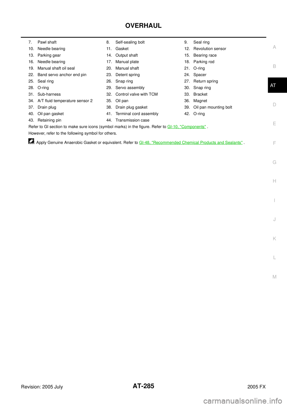
7. Pawl shaft 8. Self-sealing bolt 9. Seal ring
10. Needle bearing 11. Gasket 12. Revolution sensor
13. Parking gear 14. Output shaft 15. Bearing race
16. Needle bearing 17. Manual plate 18. Parking rod
19. Manual shaft oil seal 20. Manual shaft 21. O-ring
22. Band servo anchor end pin 23. Detent spring 24. Spacer
25. Seal ring 26. Snap ring 27. Return spring
28. O-ring 29. Servo assembly 30. Snap ring
31. Sub-harness 32. Control valve with TCM 33. Bracket
34. A/T fluid temperature sensor 2 35. Oil pan 36. Magnet
37. Drain plug 38. Drain plug gasket 39. Oil pan mounting bolt
40. Oil pan gasket 41. Terminal cord assembly 42. O-ring
43. Retaining pin 44. Transmission case
Refer to GI section to make sure icons (symbol marks) in the figure. Refer to GI-10, "
Components" .
However, refer to the following symbol for others.
: Apply Genuine Anaerobic Gasket or equivalent. Refer to GI-48, "
Recommended Chemical Products and Sealants" .
Page 380 of 4731
DISASSEMBLY AT-297
D E
F
G H
I
J
K L
M A
B
AT
Revision: 2005 July 2005 FX
33. Disconnect revolution sensor connector.
CAUTION:
Be careful not to damage connector.
34. Straighten terminal clips to free revolution sensor harness.
35. Remove bolts A, B and C from control valve with TCM.
36. Remove control valve with TCM from transmission case. CAUTION:
When removing, be careful with the manual valve notch and
manual plate height.Remove it vertically.
37. Remove A/T fluid temperature sensor 2 with bracket from con- trol valve with TCM.
SCIA5024E
SCIA5293E
Bolt symbol Length mm (in) Number of bolts
A 42 (1.65) 5
B 55 (2.17) 6
C 40 (1.57) 1
SCIA5025E
SCIA5260E
SCIA5301E
Page 387 of 4731
AT-304
DISASSEMBLY
Revision: 2005 July 2005 FX
58. Remove reverse brake piston from transmission case with com-
pressed air. Refer to AT- 2 8 6 , "
Oil Channel" .
CAUTION:
Care should be taken not to abruptly blow air. It makes pis-
tons incline, as the result, it becomes hard to disassemble
the pistons.
59. Remove D-rings from reverse brake piston.
60. Use a pin punch (4mm dia. commercial service tool) to knock out retaining pin.
61. Remove manual shaft retaining pin with nippers.
SCIA5047E
SCIA5340E
SCIA2328E
SCIA2329E
Page 388 of 4731
DISASSEMBLY AT-305
D E
F
G H
I
J
K L
M A
B
AT
Revision: 2005 July 2005 FX
62. Remove manual plate (with parking rod) from manual shaft.
63. Remove parking rod from manual plate.
64. Remove manual shaft from transmission case.
65. Remove manual shaft oil seals using a flat-bladed screwdriver.
CAUTION:
Be careful not to scratch transmission case.
66. Remove detent spring and spacer from transmission case.
SCIA5715E
SCIA5220E
SCIA5716E
SCIA2331E
SCIA5248E
Page 411 of 4731
AT-328
ASSEMBLY
Revision: 2005 July 2005 FX
ASSEMBLYPFP:00000
Assembly (1)ACS0081S
1. As shown in the figure, use a drift [commercial service tool:
22mm (0.87in)dia.] to drive manual shaft oil seals into the trans-
mission case until it is flush.
CAUTION:
�Apply ATF to manual shaft oil seals.
�Do not reuse manual shaft oil seals.
2. Install detent spring and spacer in transmission case.
3. Install manual shaft to transmission case.
4. Install parking rod to manual plate.
SCIA5259E
: 7.9 N·m (0.81 kg-m, 70 in-lb)
SCIA5248E
SCIA5716E
SCIA5220E