2005 INFINITI FX35 ignition
[x] Cancel search: ignitionPage 3911 of 4731

LT-22
HEADLAMP - XENON TYPE -
Revision: 2005 July 2005 FX
DATA MONITOR
Operation Procedure
1. Touch “DATA MONITOR” on “SELECT DIAG MODE ” screen.
2. Touch “ALL SIGNALS”, “MAIN SIGNALS” or “SELECTION FROM MENU” on “SELECT MONITOR ITEM” screen.
3. Touch the required monitoring item on “SELECTION FROM MENU”. In “ALL SIGNALS”, all items are monitored. In “MAIN SIGNALS”, predetermined items are monitored.
4. Touch “START”.
5. Touch “RECORD” while monitoring to record the status of the item being monitored. To stop recording, touch “STOP”.
All Signals, Main Signals, Selection From Menu
NOTE:
Perform monitoring of IPDM E/R data with ignition switch ON. When ignition switch is at ACC, display may not
be correct.
ALL SIGNALS Monitors all items.
MAIN SIGNALS Monitor the predetermined item.
SELECTION FROM MENU Selects items and monitors them.
Item name CONSULT-II
screen display Display
or unit Monitor item selection
Description
ALL
SIGNALS MAIN
SIGNALS SELECTION
FROM MENU
Position lights request TAIL & CLR REQ ON/OFF ×× ×Signal status input from BCM
Headlamp low beam request HL LO REQ ON/OFF ×× ×Signal status input from BCM
Headlamp high beam request HL HI REQ ON/OFF ×× ×Signal status input from BCM
Front fog lights request FR FOG REQ ON/OFF ×× ×Signal status input from BCM
Page 3913 of 4731
LT-24
HEADLAMP - XENON TYPE -
Revision: 2005 July 2005 FX
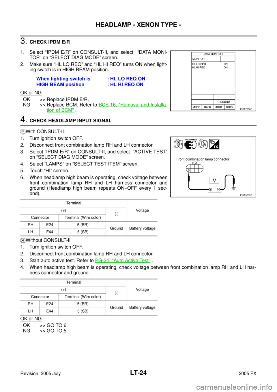
3. CHECK IPDM E/R
1. Select “IPDM E/R” on CONSULT-II, and select “DATA MONI- TOR” on “SELECT DIAG MODE” screen.
2. Make sure “HL LO REQ” and “HL HI REQ” turns ON when light- ing switch is in HIGH BEAM position.
OK or NG
OK >> Replace IPDM E/R.
NG >> Replace BCM. Refer to BCS-16, "
Removal and Installa-
tion of BCM" .
4. CHECK HEADLAMP INPUT SIGNAL
With CONSULT-II
1. Turn ignition switch OFF.
2. Disconnect front combination lamp RH and LH connector.
3. Select “IPDM E/R” on CONSULT-II, and select “ACTIVE TEST” on “SELECT DIAG MODE” screen.
4. Select “LAMPS” on “SELECT TEST ITEM” screen.
5. Touch “HI” screen.
6. When headlamp high beam is operating, check voltage between front combination lamp RH and LH harness connector and
ground (Headlamp high beam repeats ON −OFF every 1 sec-
ond).
Without CONSULT-II
1. Turn ignition switch OFF.
2. Disconnect front combination lamp RH and LH connector.
3. Start auto active test. Refer to PG-24, "
Auto Active Test" .
4. When headlamp high beam is operating, check voltage between front combination lamp RH and LH har- ness connector and ground.
OK or NG
OK >> GO TO 6.
NG >> GO TO 5. When lighting switch is
HIGH BEAM position : HL LO REQ ON
: HL HI REQ ON
PKIA7638E
Terminal
Vo l ta g e
(+)
(-)
Connector Terminal (Wire color)
RH E24 5 (BR) Ground Battery voltage
LH E44 5 (SB)
Terminal Vo l ta g e
(+)
(-)
Connector Terminal (Wire color)
RH E24 5 (BR) Ground Battery voltage
LH E44 5 (SB)
PKIA5205E
Page 3914 of 4731
HEADLAMP - XENON TYPE - LT-25
C
D E
F
G H
I
J
L
M A
B
LT
Revision: 2005 July 2005 FX
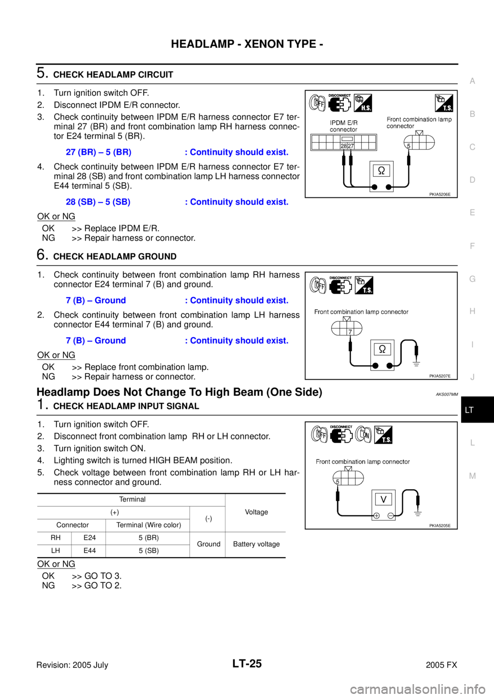
5. CHECK HEADLAMP CIRCUIT
1. Turn ignition switch OFF.
2. Disconnect IPDM E/R connector.
3. Check continuity between IPDM E/R harness connector E7 ter- minal 27 (BR) and front combination lamp RH harness connec-
tor E24 terminal 5 (BR).
4. Check continuity between IPDM E/R harness connector E7 ter- minal 28 (SB) and front combination lamp LH harness connector
E44 terminal 5 (SB).
OK or NG
OK >> Replace IPDM E/R.
NG >> Repair harness or connector.
6. CHECK HEADLAMP GROUND
1. Check continuity between front combination lamp RH harness connector E24 terminal 7 (B) and ground.
2. Check continuity between front combination lamp LH harness connector E44 terminal 7 (B) and ground.
OK or NG
OK >> Replace front combination lamp.
NG >> Repair harness or connector.
Headlamp Does Not Change To High Beam (One Side)AKS007MM
1. CHECK HEADLAMP INPUT SIGNAL
1. Turn ignition switch OFF.
2. Disconnect front combination lamp RH or LH connector.
3. Turn ignition switch ON.
4. Lighting switch is turned HIGH BEAM position.
5. Check voltage between front combination lamp RH or LH har- ness connector and ground.
OK or NG
OK >> GO TO 3.
NG >> GO TO 2. 27 (BR) – 5 (BR) : Continuity should exist.
28 (SB) – 5 (SB) : Continuity should exist.
PKIA5206E
7 (B) – Ground : Continuity should exist.
7 (B) – Ground : Continuity should exist.
PKIA5207E
Terminal Voltage
(+)
(-)
Connector Terminal (Wire color)
RH E24 5 (BR) Ground Battery voltage
LH E44 5 (SB)
PKIA5205E
Page 3915 of 4731
LT-26
HEADLAMP - XENON TYPE -
Revision: 2005 July 2005 FX
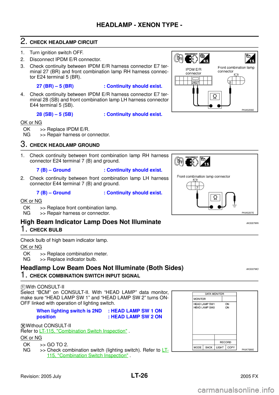
2. CHECK HEADLAMP CIRCUIT
1. Turn ignition switch OFF.
2. Disconnect IPDM E/R connector.
3. Check continuity between IPDM E/R harness connector E7 ter- minal 27 (BR) and front combination lamp RH harness connec-
tor E24 terminal 5 (BR).
4. Check continuity between IPDM E/R harness connector E7 ter- minal 28 (SB) and front combination lamp LH harness connector
E44 terminal 5 (SB).
OK or NG
OK >> Replace IPDM E/R.
NG >> Repair harness or connector.
3. CHECK HEADLAMP GROUND
1. Check continuity between front combination lamp RH harness connector E24 terminal 7 (B) and ground.
2. Check continuity between front combination lamp LH harness connector E44 terminal 7 (B) and ground.
OK or NG
OK >> Replace front combination lamp.
NG >> Repair harness or connector.
High Beam Indicator Lamp Does Not IlluminateAKS007MN
1. CHECK BULB
Check bulb of high beam indicator lamp.
OK or NG
OK >> Replace combination meter.
NG >> Replace indicator bulb.
Headlamp Low Beam Does Not Illuminate (Both Sides)AKS007MO
1. CHECK COMBINATION SWITCH INPUT SIGNAL
With CONSULT-II
Select “BCM” on CONSULT-II. With “HEAD LAMP” data monitor,
make sure “HEAD LAMP SW 1” and “HEAD LAMP SW 2” turns ON-
OFF linked with operation of lighting switch.
Without CONSULT-II
Refer to LT- 11 5 , "
Combination Switch Inspection" .
OK or NG
OK >> GO TO 2.
NG >> Check combination switch (lighting switch). Refer to LT-
11 5 , "Combination Switch Inspection" .
27 (BR) – 5 (BR) : Continuity should exist.
28 (SB) – 5 (SB) : Continuity should exist.
PKIA5206E
7 (B) – Ground : Continuity should exist.
7 (B) – Ground : Continuity should exist.
PKIA5207E
When lighting switch is 2ND
position : HEAD LAMP SW 1 ON
: HEAD LAMP SW 2 ON
PKIA7586E
Page 3917 of 4731
LT-28
HEADLAMP - XENON TYPE -
Revision: 2005 July 2005 FX
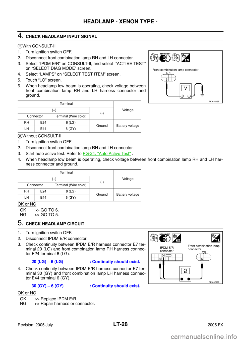
4. CHECK HEADLAMP INPUT SIGNAL
With CONSULT-II
1. Turn ignition switch OFF.
2. Disconnect front combination lamp RH and LH connector.
3. Select “IPDM E/R” on CONSULT-II, and select “ACTIVE TEST” on “SELECT DIAG MODE” screen.
4. Select “LAMPS” on “SELECT TEST ITEM” screen.
5. Touch “LO” screen.
6. When headlamp low beam is operating, check voltage between front combination lamp RH and LH harness connector and
ground.
Without CONSULT-II
1. Turn ignition switch OFF.
2. Disconnect front combination lamp RH and LH connector.
3. Start auto active test. Refer to PG-24, "
Auto Active Test" .
4. When headlamp low beam is operating, check voltage between front combination lamp RH and LH har- ness connector and ground.
OK or NG
OK >> GO TO 6.
NG >> GO TO 5.
5. CHECK HEADLAMP CIRCUIT
1. Turn ignition switch OFF.
2. Disconnect IPDM E/R connector.
3. Check continuity between IPDM E/R harness connector E7 ter- minal 20 (LG) and front combination lamp RH harness connec-
tor E24 terminal 6 (LG).
4. Check continuity between IPDM E/R harness connector E7 ter- minal 30 (GY) and front combination lamp LH harness connec-
tor E44 terminal 6 (GY).
OK or NG
OK >> Replace IPDM E/R.
NG >> Repair harness or connector.
Te r m i n a l
Vo l ta g e
(+)
(-)
Connector Terminal (Wire color)
RH E24 6 (LG) Ground Battery voltage
LH E44 6 (GY)
Te r m i n a l Vo l ta g e
(+)
(-)
Connector Terminal (Wire color)
RH E24 6 (LG) Ground Battery voltage
LH E44 6 (GY)PKIA5208E
20 (LG) – 6 (LG) : Continuity should exist.
30 (GY) – 6 (GY) : Continuity should exist.
PKIA5209E
Page 3918 of 4731
HEADLAMP - XENON TYPE - LT-29
C
D E
F
G H
I
J
L
M A
B
LT
Revision: 2005 July 2005 FX
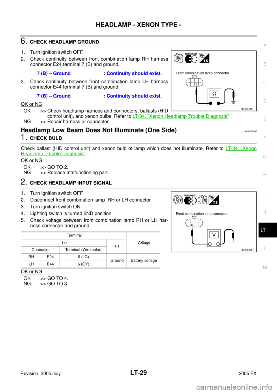
6. CHECK HEADLAMP GROUND
1. Turn ignition switch OFF.
2. Check continuity between front combination lamp RH harness connector E24 terminal 7 (B) and ground.
3. Check continuity between front combination lamp LH harness connector E44 terminal 7 (B) and ground.
OK or NG
OK >> Check headlamp harness and connectors, ballasts (HID control unit), and xenon bulbs. Refer to LT- 3 4 , "
Xenon Headlamp Trouble Diagnosis" .
NG >> Repair harness or connector.
Headlamp Low Beam Does Not Illuminate (One Side)AKS007MP
1. CHECK BULB
Check ballast (HID control unit) and xenon bulb of lamp which does not illuminate. Refer to LT- 3 4 , "
Xenon
Headlamp Trouble Diagnosis" .
OK or NG
OK >> GO TO 2.
NG >> Replace malfunctioning part.
2. CHECK HEADLAMP INPUT SIGNAL
1. Turn ignition switch OFF.
2. Disconnect front combination lamp RH or LH connector.
3. Turn ignition switch ON.
4. Lighting switch is turned 2ND position.
5. Check voltage between front combination lamp RH or LH har- ness connector and ground.
OK or NG
OK >> GO TO 4.
NG >> GO TO 3. 7 (B) – Ground : Continuity should exist.
7 (B) – Ground : Continuity should exist.
PKIA5207E
Terminal Voltage
(+)
(-)
Connector Terminal (Wire color)
RH E24 6 (LG) Ground Battery voltage
LH E44 6 (GY)
PKIA5208E
Page 3919 of 4731
LT-30
HEADLAMP - XENON TYPE -
Revision: 2005 July 2005 FX
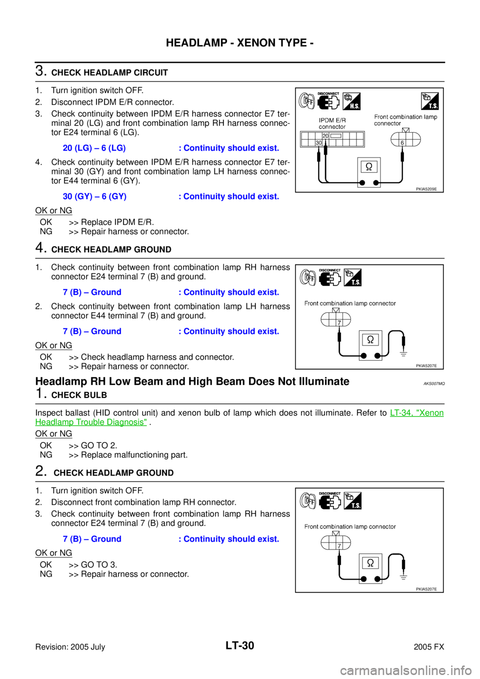
3. CHECK HEADLAMP CIRCUIT
1. Turn ignition switch OFF.
2. Disconnect IPDM E/R connector.
3. Check continuity between IPDM E/R harness connector E7 ter- minal 20 (LG) and front combination lamp RH harness connec-
tor E24 terminal 6 (LG).
4. Check continuity between IPDM E/R harness connector E7 ter- minal 30 (GY) and front combination lamp LH harness connec-
tor E44 terminal 6 (GY).
OK or NG
OK >> Replace IPDM E/R.
NG >> Repair harness or connector.
4. CHECK HEADLAMP GROUND
1. Check continuity between front combination lamp RH harness connector E24 terminal 7 (B) and ground.
2. Check continuity between front combination lamp LH harness connector E44 terminal 7 (B) and ground.
OK or NG
OK >> Check headlamp harness and connector.
NG >> Repair harness or connector.
Headlamp RH Low Beam and High Beam Does Not Illuminate AKS007MQ
1. CHECK BULB
Inspect ballast (HID control unit) and xenon bulb of lamp which does not illuminate. Refer to LT- 3 4 , "
Xenon
Headlamp Trouble Diagnosis" .
OK or NG
OK >> GO TO 2.
NG >> Replace malfunctioning part.
2. CHECK HEADLAMP GROUND
1. Turn ignition switch OFF.
2. Disconnect front combination lamp RH connector.
3. Check continuity between front combination lamp RH harness connector E24 terminal 7 (B) and ground.
OK or NG
OK >> GO TO 3.
NG >> Repair harness or connector. 20 (LG) – 6 (LG) : Continuity should exist.
30 (GY) – 6 (GY) : Continuity should exist.
PKIA5209E
7 (B) – Ground : Continuity should exist.
7 (B) – Ground : Continuity should exist.
PKIA5207E
7 (B) – Ground : Continuity should exist.
PKIA5207E
Page 3920 of 4731
HEADLAMP - XENON TYPE - LT-31
C
D E
F
G H
I
J
L
M A
B
LT
Revision: 2005 July 2005 FX
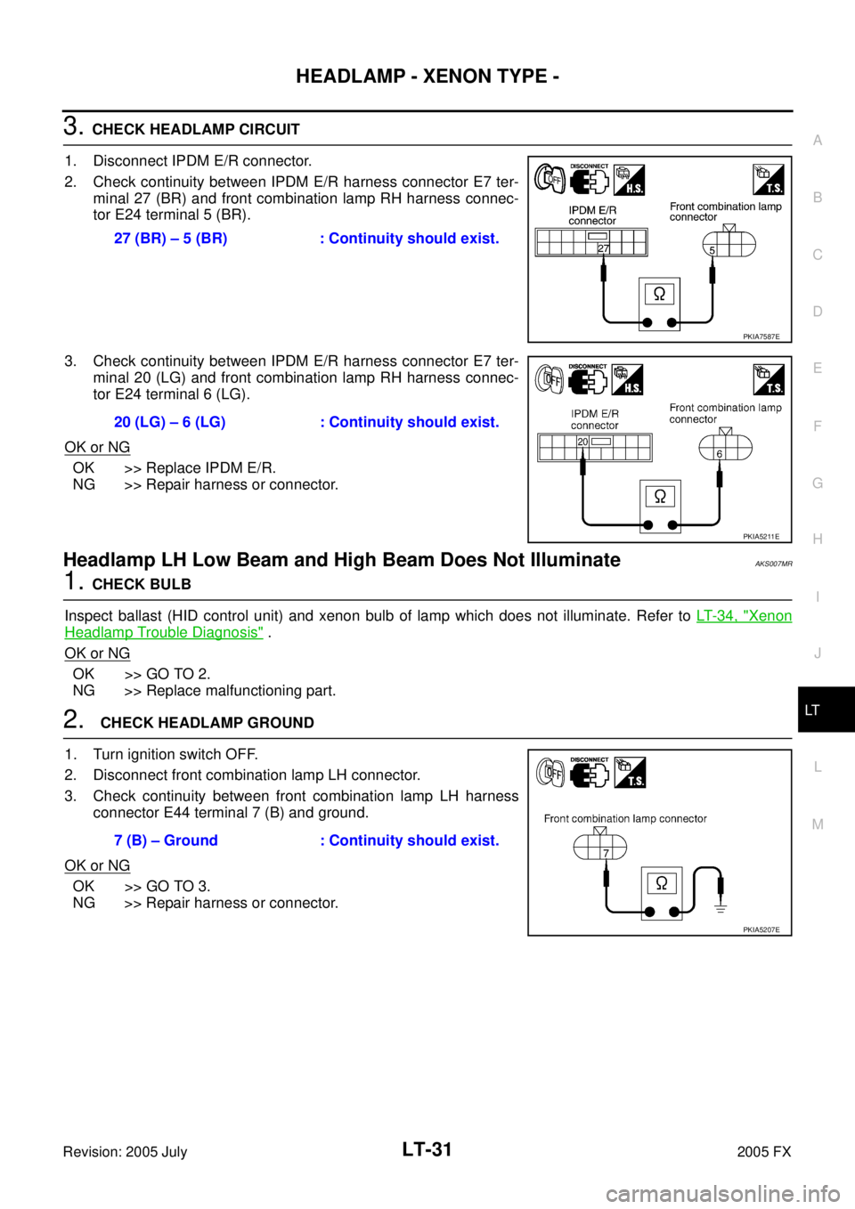
3. CHECK HEADLAMP CIRCUIT
1. Disconnect IPDM E/R connector.
2. Check continuity between IPDM E/R harness connector E7 ter- minal 27 (BR) and front combination lamp RH harness connec-
tor E24 terminal 5 (BR).
3. Check continuity between IPDM E/R harness connector E7 ter- minal 20 (LG) and front combination lamp RH harness connec-
tor E24 terminal 6 (LG).
OK or NG
OK >> Replace IPDM E/R.
NG >> Repair harness or connector.
Headlamp LH Low Beam and High Beam Does Not Illuminate AKS007MR
1. CHECK BULB
Inspect ballast (HID control unit) and xenon bulb of lamp which does not illuminate. Refer to LT- 3 4 , "
Xenon
Headlamp Trouble Diagnosis" .
OK or NG
OK >> GO TO 2.
NG >> Replace malfunctioning part.
2. CHECK HEADLAMP GROUND
1. Turn ignition switch OFF.
2. Disconnect front combination lamp LH connector.
3. Check continuity between front combination lamp LH harness connector E44 terminal 7 (B) and ground.
OK or NG
OK >> GO TO 3.
NG >> Repair harness or connector. 27 (BR) – 5 (BR) : Continuity should exist.
PKIA7587E
20 (LG) – 6 (LG) : Continuity should exist.
PKIA5211E
7 (B) – Ground : Continuity should exist.
PKIA5207E