Page 499 of 4731

ATC-62
TROUBLE DIAGNOSIS
Revision: 2005 July 2005 FX
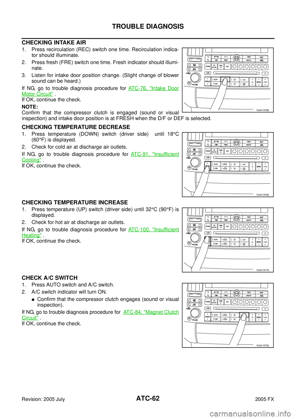
CHECKING INTAKE AIR
1. Press recirculation (REC) switch one time. Recirculation indica-
tor should illuminate.
2. Press fresh (FRE) switch one time. Fresh indicator should illumi- nate.
3. Listen for intake door position change. (Slight change of blower sound can be heard.)
If NG, go to trouble diagnosis procedure for AT C - 7 6 , "
Intake Door
Motor Circuit" .
If OK, continue the check.
NOTE:
Confirm that the compressor clutch is engaged (sound or visual
inspection) and intake door position is at FRESH when the D/F or DEF is selected.
CHECKING TEMPERATURE DECREASE
1. Press temperature (DOWN) switch (driver side) until 18 °C
(60 °F) is displayed.
2. Check for cold air at discharge air outlets.
If NG, go to trouble diagnosis procedure for AT C - 9 1 , "
Insufficient
Cooling" .
If OK, continue the check.
CHECKING TEMPERATURE INCREASE
1. Press temperature (UP) switch (driver side) until 32 °C (90 °F) is
displayed.
2. Check for hot air at discharge air outlets.
If NG, go to trouble diagnosis procedure for ATC-100, "
Insufficient
Heating" .
If OK, continue the check.
CHECK A/C SWITCH
1. Press AUTO switch and A/C switch.
2. A/C switch indicator will turn ON.
�Confirm that the compressor clutch engages (sound or visual
inspection).
If NG, go to trouble diagnosis procedure for AT C - 8 4 , "
Magnet Clutch
Circuit" .
If OK, continue the check.
RJIA1978E
RJIA1976E
RJIA1977E
RJIA1975E
Page 500 of 4731

TROUBLE DIAGNOSIS ATC-63
C
D E
F
G H
I
K L
M A
B
AT C
Revision: 2005 July 2005 FX
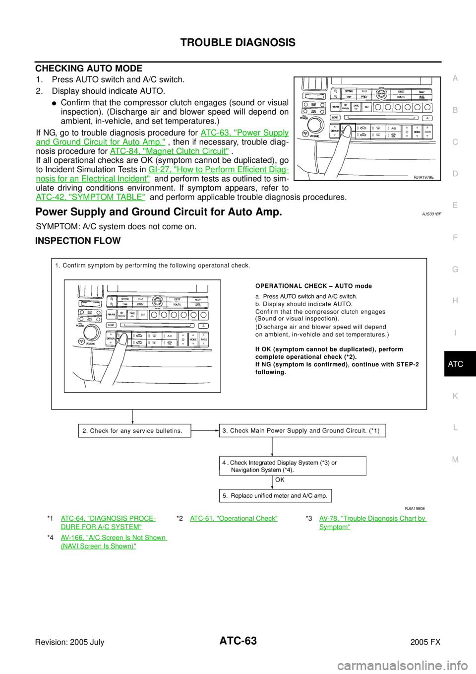
CHECKING AUTO MODE
1. Press AUTO switch and A/C switch.
2. Display should indicate AUTO.
�Confirm that the compressor clutch engages (sound or visual
inspection). (Discharge air and blower speed will depend on
ambient, in-vehicle, and set temperatures.)
If NG, go to trouble diagnosis procedure for AT C - 6 3 , "
Power Supply
and Ground Circuit for Auto Amp." , then if necessary, trouble diag-
nosis procedure for AT C - 8 4 , "
Magnet Clutch Circuit" .
If all operational checks are OK (symptom cannot be duplicated), go
to Incident Simulation Tests in GI-27, "
How to Perform Efficient Diag-
nosis for an Electrical Incident" and perform tests as outlined to sim-
ulate driving conditions environment. If symptom appears, refer to
AT C - 4 2 , "
SYMPTOM TABLE" and perform applicable trouble diagnosis procedures.
Power Supply and Ground Circuit for Auto Amp.AJS001BF
SYMPTOM: A/C system does not come on.
INSPECTION FLOW
RJIA1979E
*1 AT C - 6 4 , "DIAGNOSIS PROCE-
DURE FOR A/C SYSTEM"
*2ATC-61, "Operational Check"*3 AV- 7 8 , "Trouble Diagnosis Chart by
Symptom"
*4AV-166, "A/C Screen Is Not Shown
(NAVI Screen Is Shown)"
RJIA1980E
Page 521 of 4731
ATC-84
TROUBLE DIAGNOSIS
Revision: 2005 July 2005 FX
Magnet Clutch CircuitAJS0014Y
SYMPTOM: Magnet clutch does not engage.
INSPECTION FLOW
*1ATC-113, "Intake Sensor Circuit"*2 ATC-104, "Ambient Sensor Circuit"*3AT C - 5 4 , "FUNCTION CONFIRMA-
TION PROCEDURE", see No. 13.
*4 ATC-85, "
DIAGNOSIS PROCE-
DURE FOR MAGNET CLUTCH"
*5 ATC-96, "TROUBLE DIAGNOSIS
FOR UNUSUAL PRESSURE"
*6AT C - 6 1 , "Operational Check"
*7ATC-54, "FUNCTION CONFIRMA-
TION PROCEDURE", see No. 4 to 6. *8
ATC-42, "
SYMPTOM TABLE"
RJIA2002E
Page 522 of 4731
TROUBLE DIAGNOSIS ATC-85
C
D E
F
G H
I
K L
M A
B
AT C
Revision: 2005 July 2005 FX
SYSTEM DESCRIPTION
Unified meter and A/C amp. controls compressor operation by ambient temperature, intake air temperature
and signal from ECM.
Low Temperature Protection Control
Unified meter and A/C amp. will turn the compressor ON or OFF as determined by a signal detected by ambi-
ent sensor and intake sensor.
When ambient temperature is higher than −2 °C (28 °F), the compres-
sor turns ON. The compressor turns OFF when ambient temperature
is lower than −5 °C (23 °F).
When intake air temperature is higher than 1 °C (34 °F), the compres-
sor turns ON. The compressor turns OFF when intake air tempera-
ture is lower than −5°C (23 °F).
DIAGNOSIS PROCEDURE FOR MAGNET CLUTCH
SYMPTOM: Magnet clutch does not engage when A/C switch is ON.
RHA094GB
SJIA0267E
RJIA2003E
Page 523 of 4731

ATC-86
TROUBLE DIAGNOSIS
Revision: 2005 July 2005 FX
1. CHECK AMBIENT SENSOR AND INTAKE SENSOR CIRCUIT
Check ambient sensor and intake sensor. Refer to AT C - 5 4 , "
FUNCTION CONFIRMATION PROCEDURE" ,
see No. 9 and 11.
OK or NG
OK >> GO TO 2.
NG >>
�Malfunctioning ambient sensor: Refer to ATC-104, "Ambient Sensor Circuit" .
�Malfunctioning intake sensor: Refer to AT C - 11 3 , "Intake Sensor Circuit" .
2. PERFORM AUTO ACTIVE TEST
Refer to PG-24, "
Auto Active Test" .
Does the magnet clutch operate?
YES >>�WITH CONSULT-II
GO TO 5.
�WITHOUT CONSULT-II
GO TO 6.
NO >> Check 10 A fuse (No. 79, located in IPDM E/R), and GO TO 3.
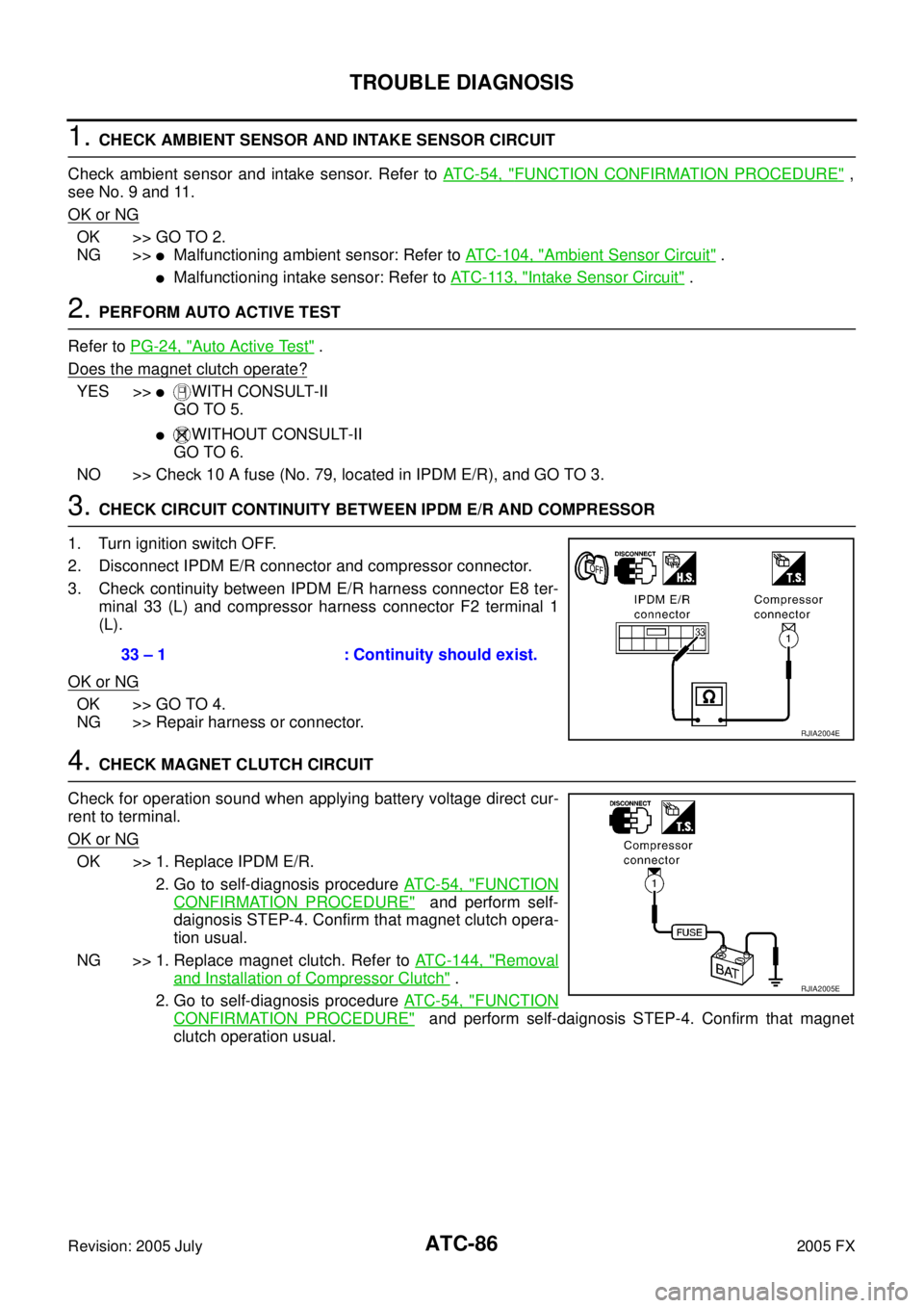
3. CHECK CIRCUIT CONTINUITY BETWEEN IPDM E/R AND COMPRESSOR
1. Turn ignition switch OFF.
2. Disconnect IPDM E/R connector and compressor connector.
3. Check continuity between IPDM E/R harness connector E8 ter- minal 33 (L) and compressor harness connector F2 terminal 1
(L).
OK or NG
OK >> GO TO 4.
NG >> Repair harness or connector.
4. CHECK MAGNET CLUTCH CIRCUIT
Check for operation sound when applying battery voltage direct cur-
rent to terminal.
OK or NG
OK >> 1. Replace IPDM E/R. 2. Go to self-diagnosis procedure AT C - 5 4 , "
FUNCTION
CONFIRMATION PROCEDURE" and perform self-
daignosis STEP-4. Confirm that magnet clutch opera-
tion usual.
NG >> 1. Replace magnet clutch. Refer to ATC-144, "
Removal
and Installation of Compressor Clutch" .
2. Go to self-diagnosis procedure AT C - 5 4 , "
FUNCTION
CONFIRMATION PROCEDURE" and perform self-daignosis STEP-4. Confirm that magnet
clutch operation usual.
33 – 1 : Continuity should exist.
RJIA2004E
RJIA2005E
Page 529 of 4731
ATC-92
TROUBLE DIAGNOSIS
Revision: 2005 July 2005 FX
*1ATC-54, "FUNCTION CONFIRMA-
TION PROCEDURE", see No. 4 to 6. *2
ATC-73, "
Air Mix Door Motor Circuit"*3ATC-95, "Test Reading"
*4 ATC-59, "AUXILIARY MECHA-
NISM: TEMPERATURE SETTING
TRIMMER"
*5ATC-54, "FUNCTION CONFIRMA-
TION PROCEDURE", see No. 13. *6
ATC-66, "
LAN System Circuit"
*7 ATC-79, "Blower Motor Circuit"*8ATC-84, "Magnet Clutch Circuit"*9ATC-93, "PERFORMANCE TEST
DIAGNOSIS"
*10 ATC-61, "Operational Check"*11AT C - 7 , "CONTAMINATED REFRIG-
ERANT"
*12EM-15, "Checking Drive Belts"
(VQ35DE) or EM-173, "
Checking
Drive Belts" (VK45DE)
*13 EC-467, "
SYSTEM DESCRIPTION"
(VQ35DE) or EC-1213, "
SYSTEM
DESCRIPTION" (VK45DE)
Page 531 of 4731
ATC-94
TROUBLE DIAGNOSIS
Revision: 2005 July 2005 FX
*1ATC-144, "Removal and Installation
of Compressor Clutch"
*2 ATC-79, "Blower Motor Circuit"*3EM-15, "Checking Drive Belts"
(VQ35DE) or EM-173, "
Checking
Drive Belts" (VK45DE)
RJIA3107E
Page 539 of 4731
ATC-102
TROUBLE DIAGNOSIS
Revision: 2005 July 2005 FX
Self-diagnosisAJS00152
SYMPTOM: Self-diagnosis cannot be performed.
INSPECTION FLOW
*1 Compressor Clutch, ATC-144,
"REMOVAL"
*2 Compressor Clutch, ATC-146,
"INSTALLATION"
*3AT C - 2 7 , "Maintenance of Lubricant
Quantity in Compressor"
*4ATC-61, "Operational Check"*5 EM-15, "Checking Drive Belts"
(VQ35DE) or EM-173, "
Checking
Drive Belts" (VK45DE)
*1 ATC-63, "
Power Supply and Ground
Circuit for Auto Amp."
*2 ATC-104, "Ambient Sensor Circuit"*3ATC-107, "In-vehicle Sensor Circuit"
*4ATC-110, "Sunload Sensor Circuit"*5 ATC-113, "Intake Sensor Circuit"*6AT C - 7 3 , "Air Mix Door Motor Circuit"
*7ATC-61, "Operational Check"*8 ATC-42, "SYMPTOM TABLE"
RJIA2014E