2005 Hyundai Tiburon flat tire
[x] Cancel search: flat tirePage 167 of 262

3
WHAT TO DO IN AN EMERGENCY
7
D060B02GK-AAT1. Obtain Spare Tire and Tool
Remove the spare tire and remove the
jack and tool bag from the trunk.
HGK4008
The jack is located behind the right side
of luggage trim. Remove the jack cover
by unscrewing the bolts. Turn the jack
end counterclockwise to lower the jack
height by using a screw driver or wrench
bar and remove it from the bracket.
HGK4009
D060C01A-AAT2. Block the Wheel
Block the wheel that is diagonally oppo-
site from the flat to keep the vehicle
from rolling when the car is raised on the
jack.
HGK4011
Flat tire
Page 169 of 262

3
WHAT TO DO IN AN EMERGENCY
9
!
WARNING:
Do not get under the car when it is
supported by the jack! This is very
dangerous as the jack could fall and
cause serious injury or death. No
one should stay in the car while the
jack is being used.
D060G02Y-AAT6. Changing Wheels
Loosen the wheel nuts and remove
them with your fingers. Slide the wheel
off the studs and lay it flat so it cannot
roll away. To put the wheel on the hub,
pick up the spare tire, line up the holes
with the studs and slide the wheel onto
them. If this is difficult, tip the wheel
slightly and get the top hole in the wheel
lined up with the top stud. Then jiggle
the wheel back and forth until the wheel
can be slid over the other studs.
HGK4031
Raise the car high enough so that the
fully inflated spare tire can be installed.
To do this, you will need more ground
clearance than is required to remove
the flat tire.
!
WARNING:
Wheels and wheel covers may have
sharp edges. Handle them carefully
to avoid possible severe injury. Be-
fore putting the wheel into place, be
sure that there is nothing on the hub
or wheel (such as mud, tar, gravel,
etc.) that interferes with the wheel
from fitting solidly against the hub. If
there is, remove it. If there is not
good contact on the mounting sur-
face between the wheel and hub, the
D060G02GK
Page 171 of 262

3
WHAT TO DO IN AN EMERGENCY
11
D060J01FC-GATAfter Changing Wheels
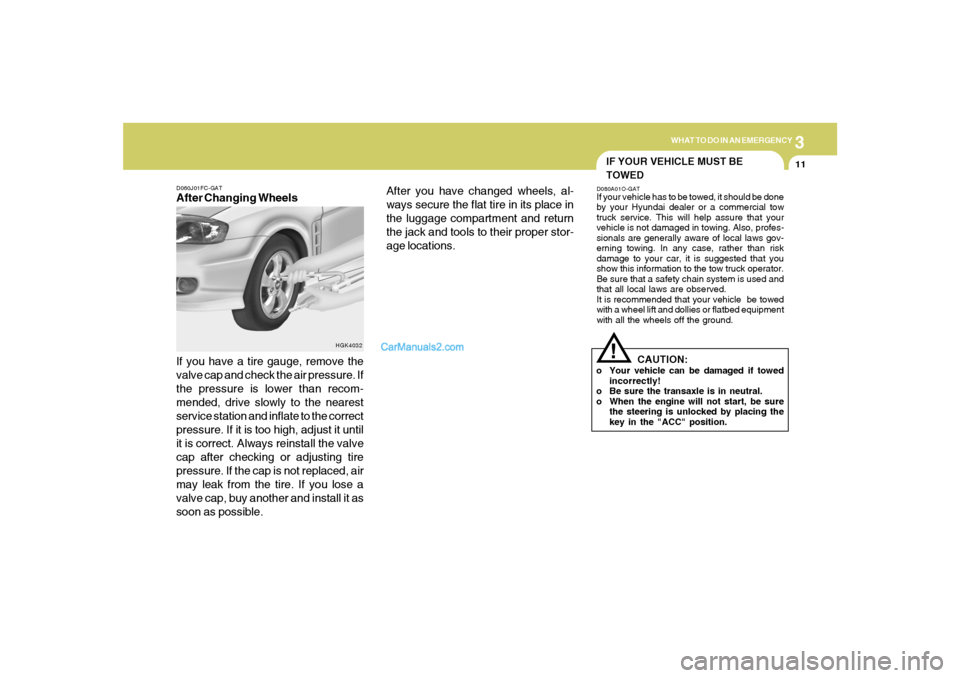
If you have a tire gauge, remove the
valve cap and check the air pressure. If
the pressure is lower than recom-
mended, drive slowly to the nearest
service station and inflate to the correct
pressure. If it is too high, adjust it until
it is correct. Always reinstall the valve
cap after checking or adjusting tire
pressure. If the cap is not replaced, air
may leak from the tire. If you lose a
valve cap, buy another and install it as
soon as possible.
HGK4032
After you have changed wheels, al-
ways secure the flat tire in its place in
the luggage compartment and return
the jack and tools to their proper stor-
age locations.
IF YOUR VEHICLE MUST BE
TOWEDD080A01O-GATIf your vehicle has to be towed, it should be done
by your Hyundai dealer or a commercial tow
truck service. This will help assure that your
vehicle is not damaged in towing. Also, profes-
sionals are generally aware of local laws gov-
erning towing. In any case, rather than risk
damage to your car, it is suggested that you
show this information to the tow truck operator.
Be sure that a safety chain system is used and
that all local laws are observed.
It is recommended that your vehicle be towed
with a wheel lift and dollies or flatbed equipment
with all the wheels off the ground.
!
CAUTION:
o Your vehicle can be damaged if towed
incorrectly!
o Be sure the transaxle is in neutral.
o When the engine will not start, be sure
the steering is unlocked by placing the
key in the "ACC" position.
Page 218 of 262

6
DO-IT-YOURSELF MAINTENANCE
29
G290B01GK-AATAdjustment After Headlight Assembly
ReplacementIf the vehicle has had front body repair and the
headlight assembly has been replaced, the
headlight aiming should be checked using an
aiming screen as shown in the illustration. Turn
on the headlight switch.
1. Adjust headlights so that main axis of light is
parallel to center line of the body and is
aligned with point "P" shown in the illustration.
2. Dotted lines in the illustration show the center
of headlights.
G290B01GK
L
W
H
H
Cut-off line
Ground line
"P"
Horizontal line
Vertical line
0.827 in. (21 mm)
HEADLIGHT AIMING ADJUSTMENT
G290A03GK G290A02GK-AAT
!
1. Keep all tires inflated to the correct pressure.
2. Place the vehicle on level ground and press
the front bumper & rear bumper down sev-
eral times. Place vehicle at a distance of 118
in. (3m) from the test wall.
3. See that the vehicle is unloaded (except for
full levels of coolant, engine oil and fuel, and
spare tire, jack, and tools).
4. Clean the head light lenses and turn on the
headlights.
5. Open the hood.
6. Draw the vertical line (through the center of
each headlight beam pattern) and the hori-
zontal line (through the center of each head-
light beam pattern) on the aiming screen.
And then, draw the parallel line at 0.827 in. (21
mm) under the horizontal line.
7. Adjust each cut-off line of the low beam to the
parallel line with a phillips screwdriver -
VERTICAL AIMING.
WARNING:
Horizontal aiming should be adjusted by an
authorized Hyundai Dealer. Low Beam
Vertical aiming
Before performing aiming adjustment, make
sure of the following.
G290A04GK
High Beam
Vertical aiming
Page 236 of 262

Vehicle Identification Number (VIN) .............................. 8-2
Engine Number ............................................................. 8-2
Recommended Inflation Pressures ............................... 8-3
Tire Sidewall Labeling ................................................... 8-4
Tire Terminology and Definitions ................................... 8-6
Snow Tires .................................................................... 8-8
Tire Chains .................................................................... 8-9
Tire Rotation .................................................................. 8-9
Tire Balancing.............................................................8-10
Tire Traction................................................................8-10
When to Replace Tires ...............................................8-10
Spare Tire and Tools ...................................................8-11
Warranties for Your Hyundai Vehicle..........................8-11
Consumer Information.................................................8-11
Reporting Safety Defects............................................8-13
Binding Arbitration of Warranty Claims.......................8-15
CONSUMER INFORMATION, REPORTING
SAFETY DEFECTS & BINDING
ARBITRATION OF WARRANTY CLAIMS
8
8
Page 238 of 262

8
CONSUMER INFORMATION, REPORTING SAFETY DEFECTS & BINDING ARBITRATION OF WARRANTY CLAIMS
3
I030A01JM-AATRECOMMENDED INFLATION PRES-
SURES
Tire label located on the driver's side of
the center pillar outer panel gives the
cold tire pressures recommended for
your vehicle with the original tire size,
the number of people that can be in your
vehicle and vehicle capacity weight.These pressures were chosen to pro-
vide the most satisfactory combination
of ride comfort, tire wear and stability
under normal conditions. Tire pressures
should be checked at least monthly.
Proper tire inflation pressures should
be maintained for these reasons:
I030B01GK
HGK6003
!
CAUTION:
Always observe the following:
o Check pressures when the tires
are cold. (After the vehicle has
been parked for at least three hours
or hasn't been driven more than 1
mile (1.6 km) since starting up.)
!
WARNING:
o Lower-than-recommended tire
pressures cause uneven tread
wear, poor handling, poor fuel
economy or tire failure.
o Higher-than-recommended tire
pressures can cause poor han-
dling, uneven tread wear or tire
failure.
Page 239 of 262

8
CONSUMER INFORMATION, REPORTING SAFETY DEFECTS & BINDING ARBITRATION OF WARRANTY CLAIMS4
Check the tire's inflation pressure when
the tires are cold. - "Cold" means your
vehicle has been sitting for at least
three hours or driven no more than 1
mile (1.6 km).
Remove the valve cap from the tire
valve stem. Press the tire gage firmly
onto the valve to get a pressure mea-
surement. If the cold tire inflation pres-
sure matches the recommended pres-
sure on the tire and loading information
label, no further adjustment is neces-
sary. If the pressure is low, add air until
you reach the recommended amount.
If you overfill the tire, release air by
pushing on the metal stem in the center
of the tire valve. Recheck the tire pres-
sure with the tire gage. Be sure to put
the valve caps back on the valve stems.
They help prevent leaks by keeping out
dirt and moisture.
I035A01JM-AATCHECKING TIRE INFLATION PRES-
SURE
Check your tires once a month or more.
Also, check the tire pressure of the
spare tire.
How to Check
Use a good quality gage to check tire
pressure. You can not tell if your tires
are properly inflated simply by looking
at them. Radial tires may look properly
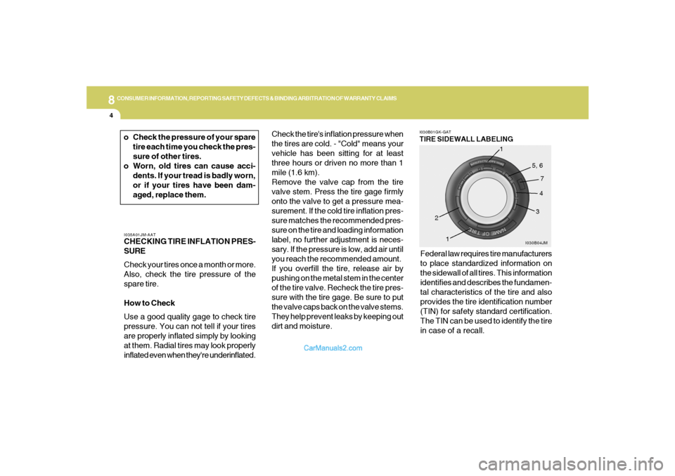
inflated even when they're underinflated.Federal law requires tire manufacturers
to place standardized information on
the sidewall of all tires. This information
identifies and describes the fundamen-
tal characteristics of the tire and also
provides the tire identification number
(TIN) for safety standard certification.
The TIN can be used to identify the tire
in case of a recall.
I030B01GK-GATTIRE SIDEWALL LABELING
I030B04JM
1
234 5, 6
7
1
o Check the pressure of your spare
tire each time you check the pres-
sure of other tires.
o Worn, old tires can cause acci-
dents. If your tread is badly worn,
or if your tires have been dam-
aged, replace them.
Page 240 of 262

8
CONSUMER INFORMATION, REPORTING SAFETY DEFECTS & BINDING ARBITRATION OF WARRANTY CLAIMS
5
1. Manufacturer or Brand name
o Manufacturer or Brand name is
shown.
2. Tire size
(example: P215/45R17 87V)
o The "P" indicates the tire is de-
signed for passenger vehicles.
A "T" is the designation for a tem-
porary spare tire.
o Three-digit number (215): This num-
ber gives the width in millimeters
of the tire from sidewall edge to
sidewall edge.
o Two-digit number (45): This num-
ber, known as the aspect ratio,
gives the tire's ratio of height to
width.
o R: The "R" stands for radial.
o Two-digit number (17): This num-
ber is the wheel or rim diameter in
inches.
o Two digit number (87): This num-
ber is the tire's load index. It is a
measurement of how much weight
each tire can support.o V: Speed Rating. The speed rating
denotes the speed at which a tire is
designed to be driven for extended
periods of time. The ratings range
from "A" to "Z" (98 to 186 MPH).
3. TIN (Tire Identification Number) for
new tire (example: DOT XX XX XXX
XXXX)
o DOT: Abbreviation for the "Depart-
ment of Transportation". The sym-
bol can be placed above, below or
to the left or right of the Tire Iden
tification Number. Indicates tire is
in compliance with the U.S. De-
partment of Transportation Motor
Vehicle Safety Standards.
o 1st two-digit code: Manufacturer's
identification mark
o 2nd two-digit code: Tire size
o 3rd three-digit code: Tire type code
(Optional)
o 4th four-digit code: Date of Manu-
factureo Four numbers represent the week
and year the tire was built. For
example, the numbers 3105 means
the 31st week of 2005.
4. Tire ply composition and material
The number of layers or plies of
rubbercoated fabric in the tire. Tire
manufacturers also must indicate
the materials in the tire, which in-
clude steel, nylon, polyester, and
others. The letter "R" means radial
ply construction; the letter "D" means
diagonal or bias ply construction;
and the letter "B" means belted-bias
ply construction.
5. Maximum permissible inflation
pressure
This number is the greatest amount
of air pressure that should be put in
the tire. Do not exceed the maximum
permissible inflation pressure. Refer
to the Tire and Loading Information
label for recommended inflation pres-
sure.