Page 366 of 539
1
CONTROLS AND EQUIPMENT
61
ZB120D1-E HIGH AND LOW BEAM
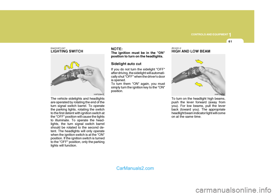
B340C03FC-EATLIGHTING SWITCH The vehicle sidelights and headlights are operated by rotating the end of the turn signal switch barrel. To operate the parking lights, rotating the switchto the first detent with ignition switch at the "OFF" position will cause the lights to illuminate. To operate the head-lights, the turn signal switch barrel should be rotated to the second de- tent. The headlights will only operatewhen the ignition switch is at the "ON" position. If the ignition switch is turned to the "OFF" position, only the parkinglights will function.
HHP2094-E NOTE: The ignition must be in the "ON" position to turn on the headlights. Sidelight auto cut If you do not turn the sidelight "OFF" after driving, the sidelight will automati-cally shut "OFF" when the driver's door is opened. To turn them "ON" again, you mustsimply turn the ignition key to the "ON" position.HHP2097-E
To turn on the headlight high beams, push the lever forward (away from you). For low beams, pull the lever back (toward you). The appropriateheadlight beam indicator light will come on at the same time.
Page 390 of 539
1
CONTROLS AND EQUIPMENT
85
This armrest is located in the centre of rear seat back. A storage box and two drink holders are included for your con- venience.PACKAGE ARMREST
HPB830A1-E
HHP2048
!
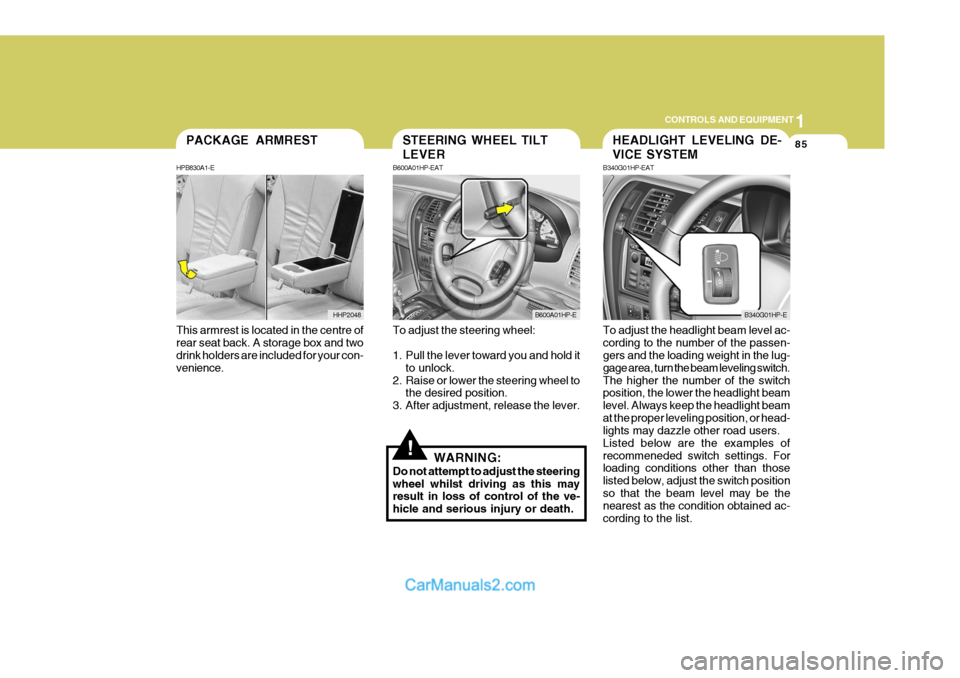
To adjust the steering wheel:
1. Pull the lever toward you and hold it to unlock.
2. Raise or lower the steering wheel to the desired position.
3. After adjustment, release the lever.
WARNING:
Do not attempt to adjust the steering wheel whilst driving as this may result in loss of control of the ve- hicle and serious injury or death. To adjust the headlight beam level ac-cording to the number of the passen- gers and the loading weight in the lug- gage area, turn the beam leveling switch.The higher the number of the switch position, the lower the headlight beam level. Always keep the headlight beamat the proper leveling position, or head- lights may dazzle other road users. Listed below are the examples ofrecommeneded switch settings. For loading conditions other than those listed below, adjust the switch positionso that the beam level may be the nearest as the condition obtained ac- cording to the list.
STEERING WHEEL TILT LEVER
B600A01HP-EAT
B600A01HP-E
HEADLIGHT LEVELING DE- VICE SYSTEM
B340G01HP-EAT
B340G01HP-E
Page 510 of 539
6
OWNER MAINTENANCE
33
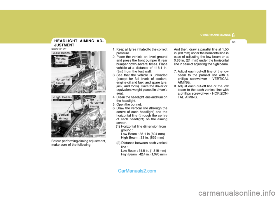
And then, draw a parallel line at 1.50 in. (38 mm) under the horizontal line incase of adjusting the low beam or at 0.83 in. (21 mm) under the horizontal line in case of adjusting the high beam.
7. Adjust each cut-off line of the low beam to the parallel line with a phillips screwdriver - VERTICAL AIMING.
8. Adjust each cut-off line of the low beam to the each vertical line witha phillips screwdriver - HORIZON-TAL AIMING.
Before performing aiming adjustment,make sure of the following.HEADLIGHT AIMING AD- JUSTMENT
G290A01HP-EAT
1. Keep all tyres inflated to the correct
pressure.
2. Place the vehicle on level ground and press the front bumper & rear bumper down several times. Placevehicle at a distance of 118.1 in. (3m) from the test wall.
3. See that the vehicle is unloaded (except for full levels of coolant, engine oil and fuel, and spare tyre,jack, and tools). Have the driver or equivalent weight placed in driver's seat.
4. Clean the headlight lens and turn on the headlight.
5. Open the bonnet.
6. Draw the vertical line (through the centre of each headlight) and thehorizontal line (through the centre of each headlight) on the aiming screen.
(1) Horizontal line dimension from
Horizontal aiming
Vertical aiming
G290B01HP
G290B02HP
Horizontal aiming
Vertical aiming
ground : Low Beam : 35.1 in.(894 mm) High Beam : 33 in. (839 mm)
(2) Distance between each vertical line :Low Beam : 51.8 in. (1,316 mm) High Beam : 42.4 in. (1,076 mm)
Page 511 of 539
6 OWNER MAINTENANCE
34
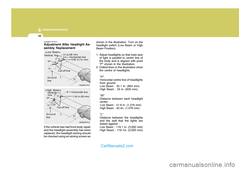
G290B01HP-EAT Adjustment After Headlight As- sembly Replacement If the vehicle has had front body repair and the headlight assembly has been replaced, the headlight aiming should be checked using an aiming screen as shown in the illustration. Turn on theheadlight switch (Low Beam or HighBeam Position).
1. Adjust headlights so that main axis
of light is parallel to centre line of the body and is aligned with point"P" shown in the illustration.
2. Dotted lines in the illustration show
the centre of headlights.
"H"Horizontal centre line of headlightsfrom ground : Low Beam : 35.1 in. (894 mm) High Beam : 33 in. (839 mm) "W" Distance between each headlight centre :
Low Beam : 51.8 in. (1,316 mm) High Beam : 42.4n. (1,076 mm) "L" Distance between the headlights and the wall that the lights are tested against : Low Beam : 118.1 in. (3,000 mm) High Beam : 118.1in. (3,000 mm)
G290B02HP-EG290B01HP-E
L
W
Cut-off line
Ground line "P"
Horizontal line
Vertical line
1.5 in.(38 mm)
0.55 in.(14 mm)
H
H
L
W
Cut-off line
Ground line "P"
Horizontal line
Vertical
0.83 in. (21mm) 1.54 in.(39 mm)
H
H
line
Page 512 of 539
6
OWNER MAINTENANCE
35
Wattage 55/55 5
21 8
10 55 55
Part Name
Headlight (Low/High Beam)Front position Light Front Turn Signal Light Map Light Interior Light Front Fog Light Side Repeater Light Front Door Edge Warning Light Wattage
10 16
No.
9
1011 12 Part Name
Luggage Compartment Light High Mounted Rear Stop Light Rear Combination Light Stop/Tail Light Turn Signal Light Back-up Light Rear Fog Light License Plate Light
No.
1 2 3 4 5 6 7 8
BULB WATTAGES
G280A01HP
G280A02HP-EAT
21/521 16 215
Page 515 of 539
6 OWNER MAINTENANCE
38
AMPERAGES15A 15A15A-
10A 10A
-
15A 15A15A15A 10A 10A10A 10A 10A 10A15A25A20A
NO. 10 NO. 11NO. 12NO. 13NO. 14NO. 15NO. 16NO. 17NO. 18NO. 19NO. 20NO. 21NO. 22NO. 23
NO. 24
NO. 25
NO. 26
NO. 27
NO. 28
NO. 29
DESCRIPTION
CIRCUIT PROTECTED
Fuel Heater and Sensor(Diesel Engine)
Headlamp(Low beam)Headlamp(High beam) -
A/C Compressor Relay, Triple Switch
TCI Fan Relay(COVEC-F/EGR)--ECM(Diesel Engine)ECM(Diesel Engine)
ECM(Diesel Engine), Air Heater Relay(Diesel Engine), EGR Solenoid(Diesel Engine)
Illuminations, Combination LampLicense Lamp, Combination Lamp
ABS Control Module, ABS Relay, EBD Relay
ECM(Diesel Engine), Headlamp Relay, Condenser Fan Relay
(Petrol/COVEC-F), EGR Solenoid(COVEC-F)ABS Control Module
Cruise Control Module
Front Wiper and Washer
Power Seat Switch
Power Outlet Relay
FUSE
Page 537 of 539
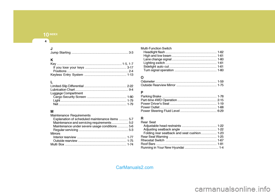
10INDEX
4
J Jump Starting .............................................................. 3-3
K
Key ....................................................................... 1-5, 1-7
If you lose y our keys ............................................. 3-17
Positions ................................................................... 2-4
Keyless Entry System .............................................. 1-13
L
Limited-Slip Differential .............................................. 2-22
Lubrication Chart .......................................................... 9-4
Luggage Compartment Cargo Security Screen ........................................... 1-80
Light ........................................................................ 1-79
Net .......................................................................... 1-79
MMaintenance Requirements Explanation of scheduled maintenance items .......... 5-7
Maintenance and servicing requirement s .................. 5-2
Maintenance under severe usage conditions ............ 5-6
Regular servici ng ...................................................... 5-3
Mirrors Interior rearview ...................................................... 1-77
Outside rearview ..................................................... 1-75
Multi Box ................................................................... 1-74Multi-Function Switch
Headlight flash ........................................................ 1-62
High and low beam ................................................. 1-61
Lane change si gnal ................................................. 1-60
Lighting switch ........................................................ 1-61
Sidelight auto cut .................................................... 1-61
Turn signal operation .............................................. 1-60
O Odometer ................................................................... 1-59
Outside Rearview Mirror ............................................ 1-75
P Parking Brake ............................................................ 1-78
Part-time 4WD Opera tion ........................................... 2-15
Power Driver's Seat ................................................... 1-19
Power Outlet .............................................................. 1-68
Power Steering Fluid Level ....... .................................6-29
R Rear Seat Adjustable head restraints ...................................... 1-22
Adjusting seatback angle ....................................... 1-22
Folding rear seatback and seat cushion .................1-23
Rear Seat Warning.................................................... 1-25
Rheostat Sw itch ........................................................ 1-67
Roof Bars .................................................................. 1-81
Running in Your New Hyundai ..................................... 1-4
Page:
< prev 1-8 9-16 17-24