2005 Hyundai Terracan audio
[x] Cancel search: audioPage 269 of 539

6
DO-IT-YOURSELF MAINTENANCE
47
AMPERAGES(A) 50A 30A 40A 40A 30A 40A 20A-
20A 10A 15A
NO. 1
NO. 2
NO. 3
NO. 4
NO. 5
NO. 6
NO. 7
NO. 8
NO. 9
DESCRIPTION
CIRCUIT PROTECTED
Power Connector(A,B), Engine Compartment Fuse and Relay Box #2
(Fuse 28,29), Inner Panel Fuse Box(Fuse 6,7,8, 9)
Start Relay, Ignition Switch
Condenser Fan Relay,
Engine Compartment Fuse and Relay Box #2(Fuse 14,15)ABS Control Module
Power Window Relay
Tail Lamp Relay,
Engine Compartment Fuse and Relay Box #2(Fuse 11,12)ABS Control Module-
Fuel Pump Relay, ECM, Ignition Failure Sensor
A/CON, TCM, ETACM, Data Link Connector, Siren,
Immobilizer Control Module
Interior Lamp, Map Lamp, Audio, Instrument Cluster,
Front Door Edge warning Lamp
FUSIBLE LINK
NO. 30
NO. 31
Page 270 of 539

6 DO-IT-YOURSELF MAINTENANCE
48
NO.1 2 34 5 67 8 9
10 11 1213 14 1516 17 1819 20 2122 23 2425 26 2728 AMPERAGES(A)
30A 10A 15A 20A10A15A30A20A 10A 10A20A10A- -
10A 10A -
10A10A10A10A 10A 10A
-
10A15A15A 10A CIRCUIT PROTECTED
Defogger Relay
Hazard Relay, Hazard Switch Stop Lamp Switch
TOD, EST Control Module - Sunroof Controller
Blower Relay
Power Door Locks
Rear Fog Lamp Relay
Audio, Map Lamp
Cigarette Lighter, Power Outlet relay, ACC Socket
Power Outside Mirror Switch- - A/C Switch
Left/Right Outside Mirror & Defogger -
TCM, ECM(COVEC-F), TCCS(TOD, EST), Immobilizer
Back-up Lamp Switch, Inside Rearview Mirror, Transmission Range Switch Hazard Switch
Instrument Cluster, ETACM, Vehicle Speed Sensor, DRL Control ModuleAirbag Airbag Indicator -
Blower & A/C, ETACM, Defogger Relay
Seat Warmer
Sunroof, Rear Wiper & Washer, Cruise Switch, Rear Intermittent Wiper Relay
Start Relay, Theft-Alarm Relay
G200E01HP-GAT Inner Panel NOTE: Not all fuse panel descriptions in this manual may be applicable to your vehicle. It is accurate at the time of printing. When you inspect the fuse box on your vehicle, refer to the fuse box label. G200D01HP
Page 289 of 539

10INDEX
2
A Air bag ....................................................................... 1-47
Air Cleaner Filter ....................................................... 6-15
Air Conditioning Care ....................................................................... 6-24
Filter ........................................................... 1-118, 6-26 Operation ................................................... 1-110, 6-25
Switch ................................................................... 1-110
Antenna ................................................................... 1-140
Ashtray ...................................................................... 1-81
Audio Fault Code .................................................... 1-137
Automatic Heating and Cooling Control System .... 1-112
B
Battery ............................................................. 2-26, 6-32 Bi-Level Heating ...................................................... 1-108
Brake
Anti-lock brake system (ABS) ................................ 2-21
Checking the brakes .............................................. 6-22
Fluid ....................................................................... 6-23
Pedal clearance ..................................................... 6-29
Pedal free-play ....................................................... 6-28
Practices ................................................................ 2-22
Breaking-In your New Hyundai ................................... 1-3C
Care of Cassette Tapes ....................
..................... 1-139
Care of Discs .......................................................... 1-138
Cargo Security Screen.............................................. 1-94
Cassette Tape Player Operation (H240) ................1-124
Cassette Tape Player Operation (H280) ................1-129
Catalytic Converter ..................................................... 7-3
CD Auto changer (H 280) .............................. 1-92, 1-134
Center Console Compartment ..................................1-87
Center console armrest .................... ..................... 1-88
Center console box ................................................ 1-87
Child Restraint System............................................. 1-39
Child-Protector Rear Door Lock ...............................1-12
Cigarette Lighter ....................................................... 1-80
Clock ......................................................................... 1-79
Clutch Checking fluid ........................................................ 6-24
Pedal free-play ....................................................... 6-28
Combination Light
Daytime running lights .... .......................................1-74
Headlight flasher .................................................... 1-75
Headlight swi tch ..................................................... 1-73
High-beam swi tch .................................................. 1-74
Lane change si gnal ................................................ 1-73
Parking light auto cut ............................................. 1-74
Turn signal oper ation............................................. 1-73
Compact Disc Player Operation (H 280) .................1-131
Cooling Fans ............................................................. 6-34
Page 373 of 539

1CONTROLS AND EQUIPMENT
68
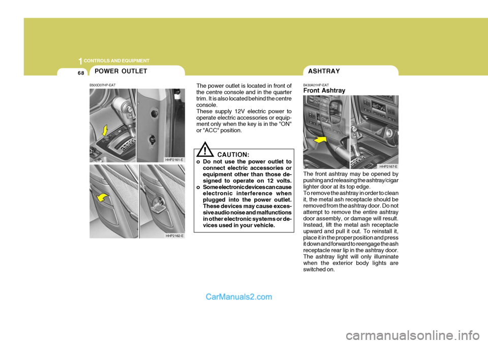
The front ashtray may be opened by pushing and releasing the ashtray/cigar lighter door at its top edge. To remove the ashtray in order to cleanit, the metal ash receptacle should be removed from the ashtray door. Do not attempt to remove the entire ashtraydoor assembly, or damage will result. Instead, lift the metal ash receptacle upward and pull it out. To reinstall it,place it in the proper position and press it down and forward to reengage the ash receptacle rear lip in the ashtray door.The ashtray light will only illuminate when the exterior body lights are switched on.ASHTRAY
B430A01HP-EAT Front Ashtray
HHP2167-E
!
The power outlet is located in front of the centre console and in the quartertrim. It is also located behind the centre console. These supply 12V electric power tooperate electric accessories or equip- ment only when the key is in the "ON" or "ACC" position.
CAUTION:
o Do not use the power outlet to connect electric accessories or equipment other than those de- signed to operate on 12 volts.
o Some electronic devices can cause electronic interference whenplugged into the power outlet.These devices may cause exces- sive audio noise and malfunctions in other electronic systems or de-vices used in your vehicle.
POWER OUTLET
B500D07HP-EAT
HHP2162-E
HHP2161-E
Page 410 of 539

1
CONTROLS AND EQUIPMENT
105STEREO SOUND SYSTEM
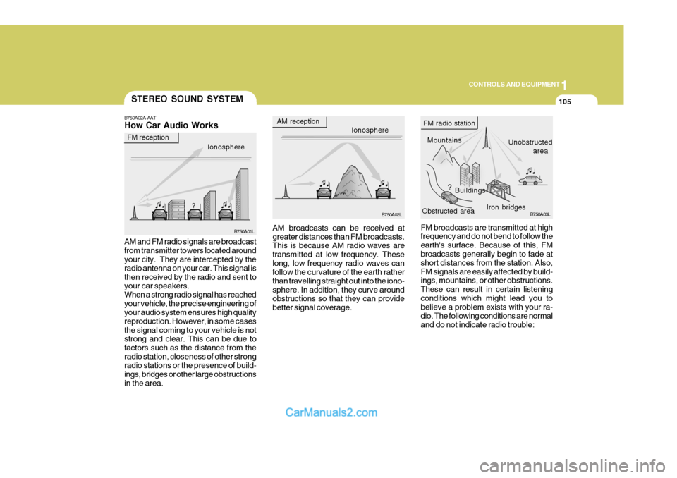
B750A02A-AAT How Car Audio Works
Ionosphere
FM reception
B750A01L
AM and FM radio signals are broadcast from transmitter towers located around your city. They are intercepted by the radio antenna on your car. This signal isthen received by the radio and sent to your car speakers. When a strong radio signal has reachedyour vehicle, the precise engineering of your audio system ensures high quality reproduction. However, in some casesthe signal coming to your vehicle is not strong and clear. This can be due to factors such as the distance from theradio station, closeness of other strong radio stations or the presence of build- ings, bridges or other large obstructionsin the area. AM broadcasts can be received atgreater distances than FM broadcasts. This is because AM radio waves are transmitted at low frequency. Theselong, low frequency radio waves can follow the curvature of the earth rather than travelling straight out into the iono-sphere. In addition, they curve around obstructions so that they can provide better signal coverage.
AM reception
Ionosphere
B750A02L
MountainsBuildings Unobstructed
area
FM radio station
B750A03L
Obstructed area Iron bridges
FM broadcasts are transmitted at high frequency and do not bend to follow the earth's surface. Because of this, FM broadcasts generally begin to fade at short distances from the station. Also,FM signals are easily affected by build- ings, mountains, or other obstructions. These can result in certain listeningconditions which might lead you to believe a problem exists with your ra- dio. The following conditions are normaland do not indicate radio trouble:
Page 411 of 539

1CONTROLS AND EQUIPMENT
106
!
B750B02Y-AAT Using a cellular phone or a two- way radio When a cellular phone is used inside the vehicle, noise may be producedfrom the audio equipment. This does not mean that something is wrong with the audio equipment. In such a case,use the cellular phone at a place as far as possible from the audio equipment.
CAUTION:
When using a communication sys- tem such a cellular phone or a radio set inside the vehicle, a separate external antenna must be fitted.When a cellular phone or a radio set is used with an internal antenna alone, it may interfere with thevehicle's electrical system and ad- versely affect safe operation of the vehicle.
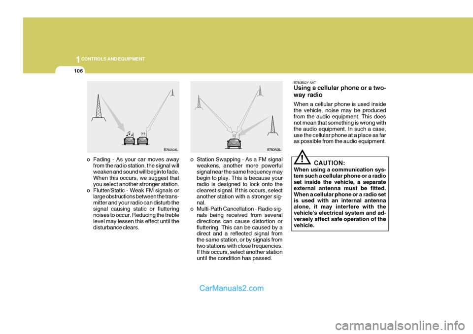
o Fading - As your car moves away
from the radio station, the signal willweaken and sound will begin to fade. When this occurs, we suggest that you select another stronger station.
o Flutter/Static - Weak FM signals or large obstructions between the trans-mitter and your radio can disturb thesignal causing static or fluttering noises to occur. Reducing the treble level may lessen this effect until thedisturbance clears. o Station Swapping - As a FM signal
weakens, another more powerfulsignal near the same frequency may begin to play. This is because your radio is designed to lock onto theclearest signal. If this occurs, select another station with a stronger sig- nal.
o Multi-Path Cancellation - Radio sig- nals being received from severaldirections can cause distortion orfluttering. This can be caused by a direct and a reflected signal from the same station, or by signals fromtwo stations with close frequencies. If this occurs, select another station until the condition has passed.
B750A04L B750A05L
Page 516 of 539

6
OWNER MAINTENANCE
39
AMPERAGES 50A 30A 40A 40A 30A 40A 20A-
20A 10A
15A
NO. 1
NO. 2
NO. 3
NO. 4
NO. 5
NO. 6
NO. 7
NO. 8
NO. 9
DESCRIPTION
CIRCUIT PROTECTED
Power Connector(A,B), Engine Compartment Fuse and Relay #2
(Fuse 28,29), Inner Panel Fuse Box(Fuse 6,7,8, 9)
Start Relay, Ignition Switch
Condenser Fan Relay, Engine Compar tment Fuse and Relay Box #2(Fuse 14,15)ABS Control Module
Power Window Relay
Tail Lamp Relay, Engine Compartment Fuse and Relay Box #2(Fuse 11,12)ABS Control Module-
Fuel Pump Relay, ECM, Ignition Failure Sensor
A/CON, TCM, ETACM, Data Link Connector, Siren, ImmobiliserControl Module
Interior Lamp, Map Lamp, Audio, Instrument Cluster, Front Door EdgeWarning Lamp
FUSIBLE LINK
NO. 30
NO. 31
Page 517 of 539

6 OWNER MAINTENANCE
40
NO.1 2 34 5 67 8 9
10 11 1213 14 1516 17 1819 20 2122 23 2425 26 2728 AMPERAGES
30A 10A 15A 20A10A15A30A20A 10A 10A20A10A- -
10A 10A -
10A10A10A10A 10A 10A
-
10A15A15A 10A CIRCUIT PROTECTED
Defogger Relay
Hazard Relay, Hazard Switch Stop Lamp Switch
TOD, EST Control Module - Sunroof Controller
Blower Relay
Power Door Locks
Rear Fog Lamp RelayAudio, Map Lamp
Cigar Lighter, Power Outlet relay, ACC Socket
Power Outside Mirror Switch- - A/C Switch
Left/Right Outside Mirror & Defogger -
TCM, ECM(COVEC-F), TCCS(TOD, EST), Immobiliser
Back-up Lamp Switch, Inside Rearview Mirror, Transmission Range Switch Hazard Switch
Instrument Cluster, ETACM, Vehicle Speed Sensor, DRL Control ModuleAirbag Airbag Indicator -
Blower & A/C, ETACM, Defogger Relay
Seat Warmer
Sunroof, Rear Wiper & Washer, Cruise Switch, Rear Intermittent Wiper Relay
Start Relay, Theft-Alarm Relay
G200E01HP-EAT Inner Panel NOTE: Not all fuse panel descriptions in this manual may be applicable to your vehicle. It is accurate at the time of printing. When you inspect the fuse box on your vehicle, refer to the fuse box label. G200D01HP