Page 394 of 539
1
CONTROLS AND EQUIPMENT
89
B710B01S-DAT CENTRE VENTILATOR The centre ventilators are located in the middle of the dashboard. The direction of air flow from the vents in the centreof the dashboard is adjustable. To control the direction of the air flow, move the knob in the centre of the ventup-and-down and side-to-side. B710C02HP-DAT SIDE VENTILATOR The side ventilators are located on each side of dashboard. To change the direction of the air flow, move the knob in the centre of the vent up-and-downand side-to-side. The vents are opened when the vent knob is moved to " " position. The vents are closed when thevent knob is moved to " ". Keep these vents clear of any obstructions.
HEATING AND COOLING CONTROL
B710A01HP-EAT
1. Side Ventilator
2. Side Defroster Nozzle
3. Windscreen Defroster Nozzle
4. Centre Ventilator B710B01HP-E
Page 395 of 539
1CONTROLS AND EQUIPMENT
90
B670B01A-AAT Fan Speed Control (Blower Con- trol)
There are four controls for the heating and cooling system. They are:
1. Fan speed control. This is used to turn the fan on and select the fan speed.
2. Air intake control. This allows you to select fresh out-side air or recirculation inside air.
3. Temperature control. This is used to turn the heatingsystem on and off and to select the degree of heating desired. 4. Air flow control.
This is used to direct the flow of air.Air can be directed to the floor, dashboard outlets, or windscreen. Five symbols are used to representFace, Bi-Level, Floor, Floor-Defrost and Defrost air positions.
This is used to turn the blower fan on and off and to select the fan speed. The blower fan speed, and therefore the volume of air delivered from thesystem, may be controlled manually by setting the blower control between the "1" and "4" position.
B670A01HP
HHP2123
HEATING AND VENTILA- TION
B670A01HP-EAT
Page 396 of 539

1
CONTROLS AND EQUIPMENT
91
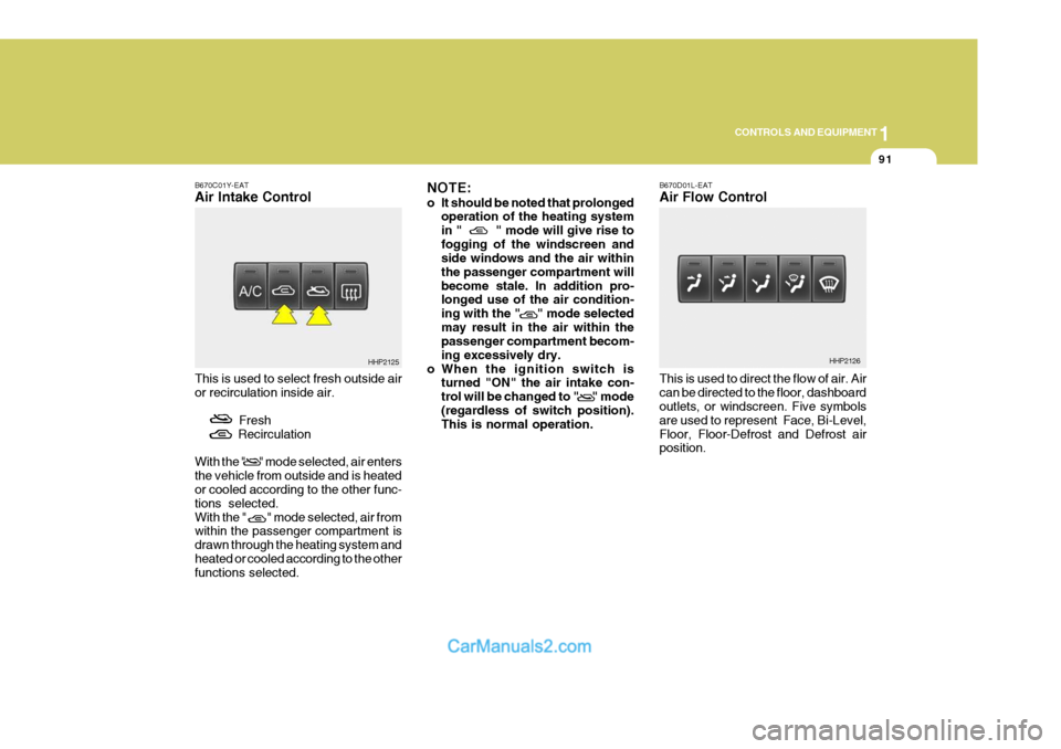
B670C01Y-EAT Air Intake Control This is used to select fresh outside air or recirculation inside air.
Fresh
Recirculation With the " " mode selected, air enters the vehicle from outside and is heated or cooled according to the other func- tions selected.With the " " mode selected, air from within the passenger compartment is drawn through the heating system andheated or cooled according to the other functions selected. NOTE:
o It should be noted that prolonged
operation of the heating system in " " mode will give rise tofogging of the windscreen and side windows and the air within the passenger compartment willbecome stale. In addition pro- longed use of the air condition- ing with the " " mode selectedmay result in the air within the passenger compartment becom- ing excessively dry.
o When the ignition switch is turned "ON" the air intake con-trol will be changed to " " mode(regardless of switch position). This is normal operation. B670D01L-EAT Air Flow Control This is used to direct the flow of air. Air can be directed to the floor, dashboard outlets, or windscreen. Five symbols are used to represent Face, Bi-Level,Floor, Floor-Defrost and Defrost air position.
HHP2125HHP2126
Page 407 of 539
1CONTROLS AND EQUIPMENT
102
B980E01L-EAT Air Flow Control This is used to direct the flow of air. Air can be directed to the floor, dashboard outlets, or windscreen. Four symbols are used to represent Face, Bi-Level,Floor and Floor-Defrost air position. Face-Level
When selecting the "Face" mode, theindicator light will come on, causing airto be discharged through the face level vents.
HHP2145
B670D01HP-E
o When the ignition switch is turned "ON" the air intake control will be changed to ( )mode (regard- less of switch position). This is normal operation. The air intakecontrol operates in "AUTO" mode when turning the ignition to the ON position if the "AUTO" modewas used before shutting off the engine.
B980D01Y-AAT Heating and Cooling System Off
HHP2140
Press the "OFF" button to stop the operation of the heating and coolingsystem.
Page 408 of 539
1
CONTROLS AND EQUIPMENT
103
Floor-Level
When selecting the "Floor-Level" mode, the indicator light will come on and theair will be discharged through the floor vents, windscreen defrost nozzle, side defroster nozzle and side ventilator. Floor-Defrost Level
When selecting the "Floor-Defrost"mode, the indicator light will come onand the air will be discharged through the windscreen defrost nozzle, the floor vents, side defroster nozzle and sideventilator.
B670D03HP-EB670D04HP-EB670D02HP-E
Bi-Level
When selecting the "Bi-Level" mode, the indicator light will come on and theair will be discharged through the face vents and the floor vents. This makes it possible to have cooler air from thedashboard vents and warmer air from the floor outlets at the same time.
Page 503 of 539

6 OWNER MAINTENANCE
26
!
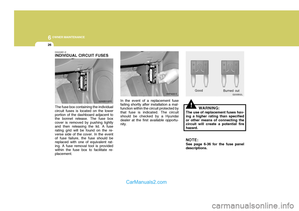
DG200B1-E INDIVIDUAL CIRCUIT FUSES The fuse box containing the individual circuit fuses is located on the lowerportion of the dashboard adjacent to the bonnet release. The fuse box cover is removed by pushing lightlyand then releasing the lid. A fuse rating grid will be found on the re- verse side of the cover. In the eventof fuse failure, the fuse should be replaced with one of equivalent rat- ing. A fuse removal tool is providedwithin the fuse box to facilitate re- placement. In the event of a replacement fuse
failing shortly after installation a mal- function within the circuit protected bythat fuse is indicated. The circuit should be checked by a Hyundai dealer at the first available opportu-nity. WARNING:
The use of replacement fuses hav-
ing a higher rating than specifiedor other means of connecting the circuit will create a potential fire hazard.
NOTE: See page 6-36 for the fuse panel
descriptions.
G200B01HP-E
HHP4002-EGood G200B02L
Burned out