Page 509 of 539
6 OWNER MAINTENANCE
32
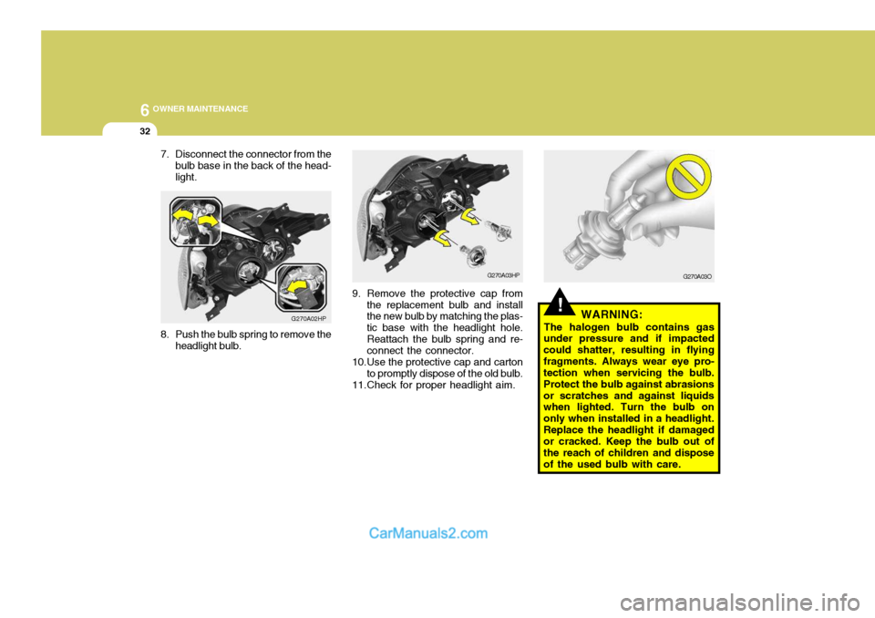
7. Disconnect the connector from the
bulb base in the back of the head- light.
G270A02HP
8. Push the bulb spring to remove the headlight bulb.
!WARNING:
The halogen bulb contains gas
under pressure and if impacted could shatter, resulting in flyingfragments. Always wear eye pro- tection when servicing the bulb. Protect the bulb against abrasionsor scratches and against liquids when lighted. Turn the bulb on only when installed in a headlight.Replace the headlight if damaged or cracked. Keep the bulb out of the reach of children and disposeof the used bulb with care.
G270A03HP
9. Remove the protective cap from the replacement bulb and install the new bulb by matching the plas- tic base with the headlight hole.Reattach the bulb spring and re- connect the connector.
10.Use the protective cap and carton to promptly dispose of the old bulb.
11.Check for proper headlight aim. G270A03O
Page 510 of 539
6
OWNER MAINTENANCE
33
And then, draw a parallel line at 1.50 in. (38 mm) under the horizontal line incase of adjusting the low beam or at 0.83 in. (21 mm) under the horizontal line in case of adjusting the high beam.
7. Adjust each cut-off line of the low beam to the parallel line with a phillips screwdriver - VERTICAL AIMING.
8. Adjust each cut-off line of the low beam to the each vertical line witha phillips screwdriver - HORIZON-TAL AIMING.
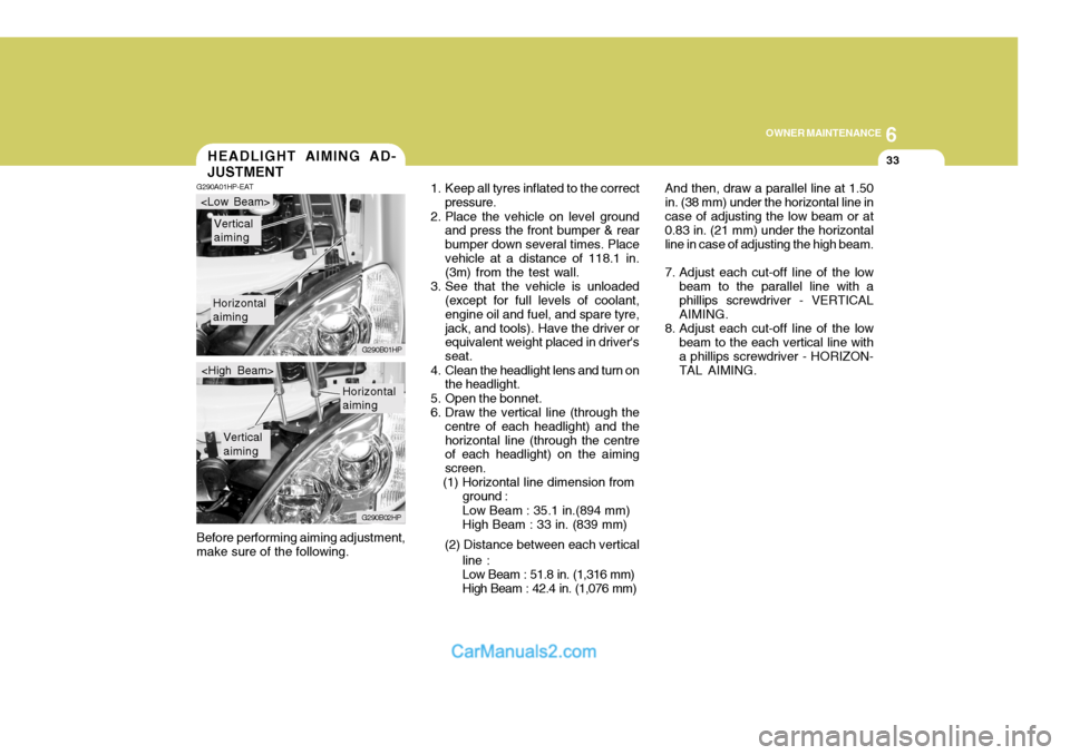
Before performing aiming adjustment,make sure of the following.HEADLIGHT AIMING AD- JUSTMENT
G290A01HP-EAT
1. Keep all tyres inflated to the correct
pressure.
2. Place the vehicle on level ground and press the front bumper & rear bumper down several times. Placevehicle at a distance of 118.1 in. (3m) from the test wall.
3. See that the vehicle is unloaded (except for full levels of coolant, engine oil and fuel, and spare tyre,jack, and tools). Have the driver or equivalent weight placed in driver's seat.
4. Clean the headlight lens and turn on the headlight.
5. Open the bonnet.
6. Draw the vertical line (through the centre of each headlight) and thehorizontal line (through the centre of each headlight) on the aiming screen.
(1) Horizontal line dimension from
Horizontal aiming
Vertical aiming
G290B01HP
G290B02HP
Horizontal aiming
Vertical aiming
ground : Low Beam : 35.1 in.(894 mm) High Beam : 33 in. (839 mm)
(2) Distance between each vertical line :Low Beam : 51.8 in. (1,316 mm) High Beam : 42.4 in. (1,076 mm)
Page 511 of 539
6 OWNER MAINTENANCE
34
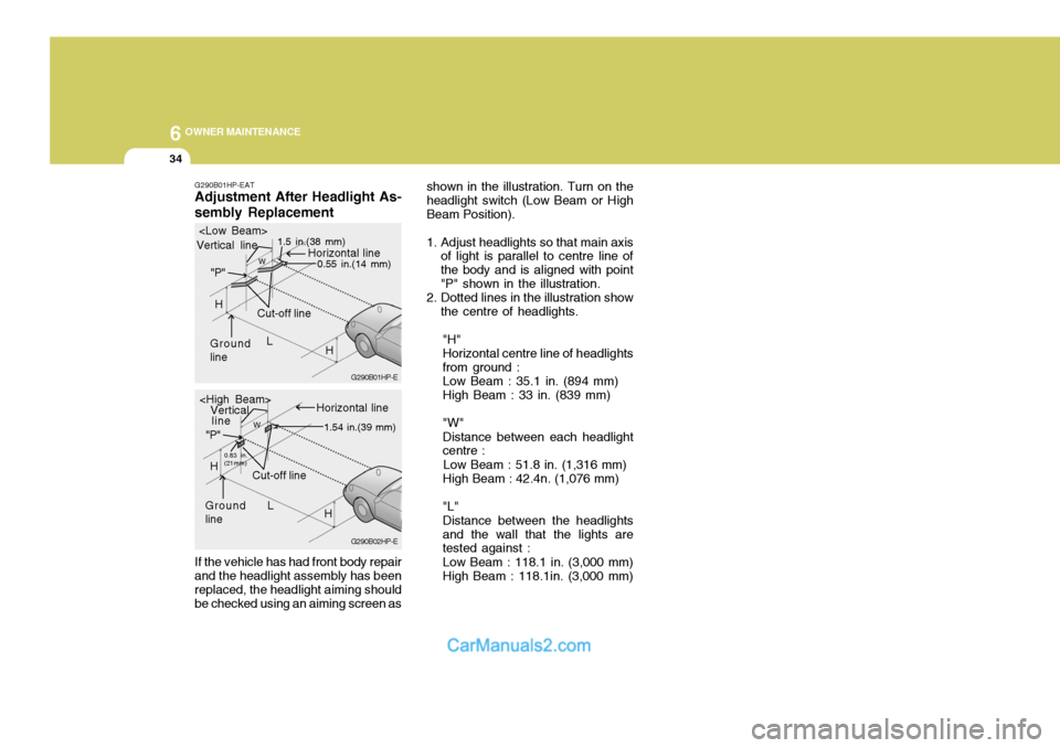
G290B01HP-EAT Adjustment After Headlight As- sembly Replacement If the vehicle has had front body repair and the headlight assembly has been replaced, the headlight aiming should be checked using an aiming screen as shown in the illustration. Turn on theheadlight switch (Low Beam or HighBeam Position).
1. Adjust headlights so that main axis
of light is parallel to centre line of the body and is aligned with point"P" shown in the illustration.
2. Dotted lines in the illustration show
the centre of headlights.
"H"Horizontal centre line of headlightsfrom ground : Low Beam : 35.1 in. (894 mm) High Beam : 33 in. (839 mm) "W" Distance between each headlight centre :
Low Beam : 51.8 in. (1,316 mm) High Beam : 42.4n. (1,076 mm) "L" Distance between the headlights and the wall that the lights are tested against : Low Beam : 118.1 in. (3,000 mm) High Beam : 118.1in. (3,000 mm)
G290B02HP-EG290B01HP-E
L
W
Cut-off line
Ground line "P"
Horizontal line
Vertical line
1.5 in.(38 mm)
0.55 in.(14 mm)
H
H
L
W
Cut-off line
Ground line "P"
Horizontal line
Vertical
0.83 in. (21mm) 1.54 in.(39 mm)
H
H
line
Page 512 of 539
6
OWNER MAINTENANCE
35
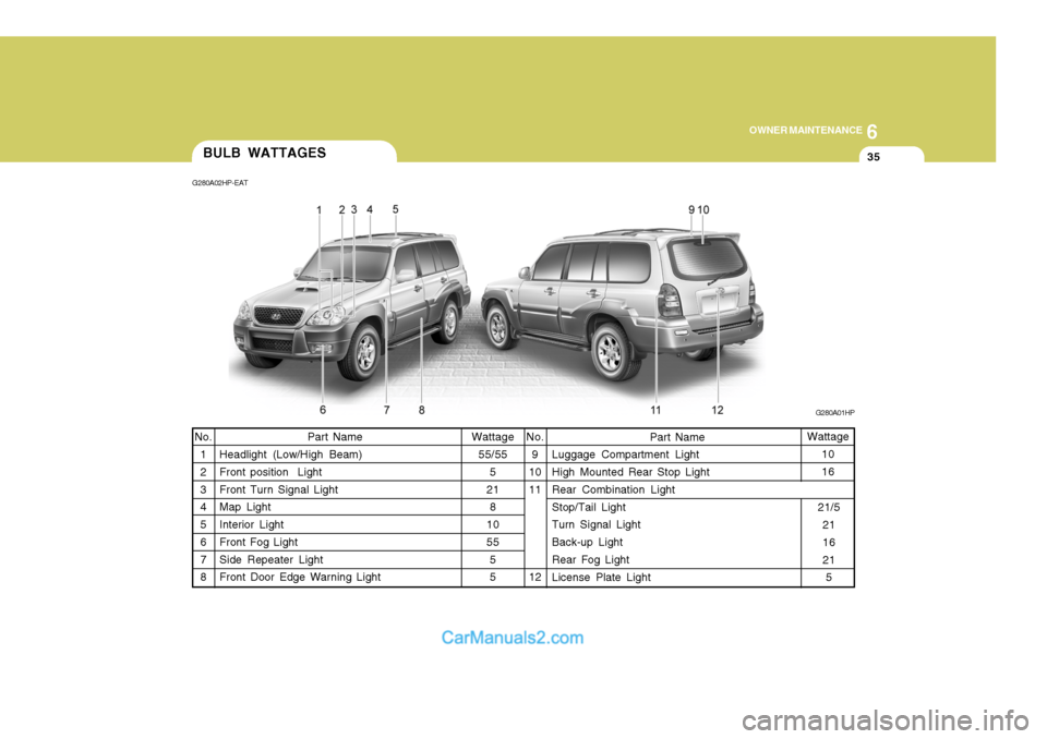
Wattage 55/55 5
21 8
10 55 55
Part Name
Headlight (Low/High Beam)Front position Light Front Turn Signal Light Map Light Interior Light Front Fog Light Side Repeater Light Front Door Edge Warning Light Wattage
10 16
No.
9
1011 12 Part Name
Luggage Compartment Light High Mounted Rear Stop Light Rear Combination Light Stop/Tail Light Turn Signal Light Back-up Light Rear Fog Light License Plate Light
No.
1 2 3 4 5 6 7 8
BULB WATTAGES
G280A01HP
G280A02HP-EAT
21/521 16 215
Page 513 of 539
6 OWNER MAINTENANCE
36
NO.1
NO. 2
NO. 3
NO.4
NO.5
NO. 6
NO. 7
NO. 8
NO. 9
NO. 10
NO. 11
NO. 12
DESCRIPTION
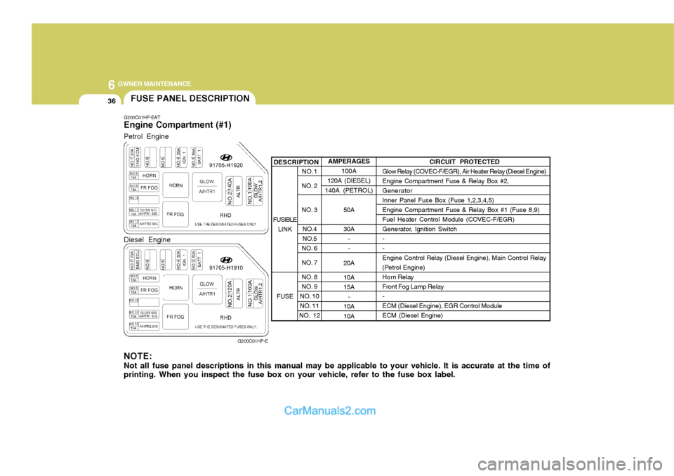
G200C01HP-EAT Engine Compartment (#1)
G200C01HP-E
NOTE: Not all fuse panel descriptions in this manual may be applicable to your vehicle. It is accurate at the time of printing. When you inspect the fuse box on your vehicle, refer to the fuse box label. AMPERAGES
100A
120A (DIESEL)
140A ( PETROL)
50A 30A - -
20A 10A 15A -
10A10A CIRCUIT PROTECTED
Glow Relay (COVEC-F/EGR), Air Heater Relay (Diesel Engine) Engine Compartment Fuse & Relay Box #2,GeneratorInner Panel Fuse Box (Fuse 1,2,3,4,5)Engine Compartment Fuse & Relay Box #1 (Fuse 8,9)
Fuel Heater Control Module (COVEC-F/EGR)
Generator, Ignition Switch--Engine Control Relay (Diesel Engine), Main Control Relay
(Petrol Engine)
Horn Relay
Front Fog Lamp Relay-ECM (Diesel Engine), EGR Control ModuleECM (Diesel Engine)
FUSIBLE LINK
FUSE
FUSE PANEL DESCRIPTION
Petrol Engine Diesel Engine
Page 514 of 539
6
OWNER MAINTENANCE
37
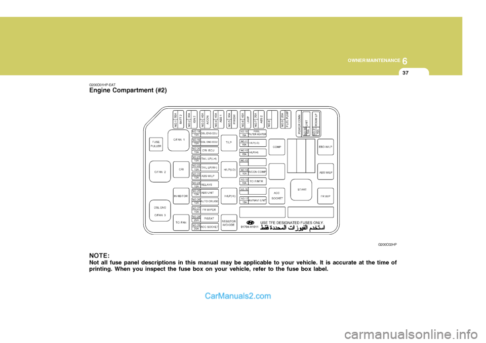
NOTE: Not all fuse panel descriptions in this manual may be applicable to your vehicle. It is accurate at the time of printing. When you inspect the fuse box on your vehicle, refer to the fuse box label.
G200D01HP-EAT
Engine Compartment (#2)
G200C02HP
Page 515 of 539
6 OWNER MAINTENANCE
38
AMPERAGES15A 15A15A-
10A 10A
-
15A 15A15A15A 10A 10A10A 10A 10A 10A15A25A20A
NO. 10 NO. 11NO. 12NO. 13NO. 14NO. 15NO. 16NO. 17NO. 18NO. 19NO. 20NO. 21NO. 22NO. 23
NO. 24
NO. 25
NO. 26
NO. 27
NO. 28
NO. 29
DESCRIPTION
CIRCUIT PROTECTED
Fuel Heater and Sensor(Diesel Engine)
Headlamp(Low beam)Headlamp(High beam) -
A/C Compressor Relay, Triple Switch
TCI Fan Relay(COVEC-F/EGR)--ECM(Diesel Engine)ECM(Diesel Engine)
ECM(Diesel Engine), Air Heater Relay(Diesel Engine), EGR Solenoid(Diesel Engine)
Illuminations, Combination LampLicense Lamp, Combination Lamp
ABS Control Module, ABS Relay, EBD Relay
ECM(Diesel Engine), Headlamp Relay, Condenser Fan Relay
(Petrol/COVEC-F), EGR Solenoid(COVEC-F)ABS Control Module
Cruise Control Module
Front Wiper and Washer
Power Seat Switch
Power Outlet Relay
FUSE
Page 516 of 539
6
OWNER MAINTENANCE
39
AMPERAGES 50A 30A 40A 40A 30A 40A 20A-
20A 10A
15A
NO. 1
NO. 2
NO. 3
NO. 4
NO. 5
NO. 6
NO. 7
NO. 8
NO. 9
DESCRIPTION
CIRCUIT PROTECTED
Power Connector(A,B), Engine Compartment Fuse and Relay #2
(Fuse 28,29), Inner Panel Fuse Box(Fuse 6,7,8, 9)
Start Relay, Ignition Switch
Condenser Fan Relay, Engine Compar tment Fuse and Relay Box #2(Fuse 14,15)ABS Control Module
Power Window Relay
Tail Lamp Relay, Engine Compartment Fuse and Relay Box #2(Fuse 11,12)ABS Control Module-
Fuel Pump Relay, ECM, Ignition Failure Sensor
A/CON, TCM, ETACM, Data Link Connector, Siren, ImmobiliserControl Module
Interior Lamp, Map Lamp, Audio, Instrument Cluster, Front Door EdgeWarning Lamp
FUSIBLE LINK
NO. 30
NO. 31