Page 507 of 539
6 OWNER MAINTENANCE
30
!
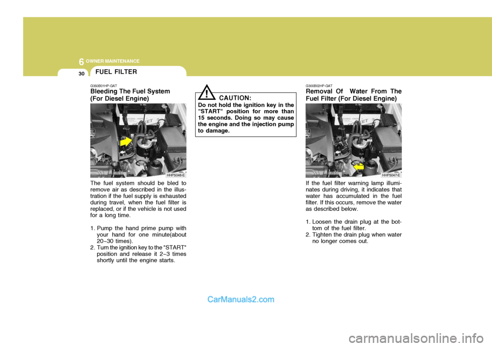
The fuel system should be bled to remove air as described in the illus- tration if the fuel supply is exhausted during travel, when the fuel filter isreplaced, or if the vehicle is not used for a long time.
1. Pump the hand prime pump with your hand for one minute(about 20~30 times).
2. Turn the ignition key to the "START" position and release it 2~3 times shortly until the engine starts. CAUTION:
Do not hold the ignition key in the
"START" position for more than 15 seconds. Doing so may causethe engine and the injection pump to damage. G300B02HP-GAT
Removal Of Water From The Fuel Filter (For Diesel Engine)
If the fuel filter warning lamp illumi-
nates during driving, it indicates that water has accumulated in the fuel filter. If this occurs, remove the wateras described below.
1. Loosen the drain plug at the bot- tom of the fuel filter.
2. Tighten the drain plug when water no longer comes out.
FUEL FILTER
G350B01HP-GAT Bleeding The Fuel System (For Diesel Engine)
HHP5048-EHHP5047-E
Page 508 of 539
6
OWNER MAINTENANCE
31
!
!
3. Check to be sure that the warning
lamp illuminates when the ignition key is turned to "ON", and that it goes off when the engine is started. If in doubt, consult your nearest authorised HYUNDAI dealer.
NOTE: It is recommended that water accu- mulated in the fuel filter should be removed by an authorised Hyundai dealer.
WARNING:
Be sure to carefully wipe away anywater drained out in this manner, because the fuel mixed in the water might be ignited and resultin a fire. Before attempting to replace a head-
light bulb, be sure the switch is turned to the "OFF" position.
The next paragraph shows how to
reach the headlight bulbs so they may be changed. Be sure to replacethe burned-out bulb with one of the same number and wattage rating.
Ensure that the replacement bulb has
the same cap configuration and watt-age as the original.
See page 6-35 for the wattage descrip-
tions.
CAUTION:
Keep the lamps out of contact with
petroleum product, such as oil, petrol, etc.
REPLACING HEADLIGHT BULBS
G260A01HP-EAT
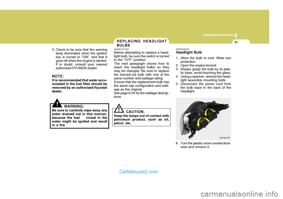
G270A01B-EAT Headlight Bulb
1. Allow the bulb to cool. Wear eye
protection.
2. Open the engine bonnet.
3. Always grasp the bulb by its plas- tic base, avoid touching the glass.
4. Using a spanner, remove the head- light assembly mounting bolts.
5. Disconnect the power cord from the bulb base in the back of the headlight.
G270A01HP
6. Turn the plastic cover counterclock- wise and remove it.
Page 510 of 539
6
OWNER MAINTENANCE
33
And then, draw a parallel line at 1.50 in. (38 mm) under the horizontal line incase of adjusting the low beam or at 0.83 in. (21 mm) under the horizontal line in case of adjusting the high beam.
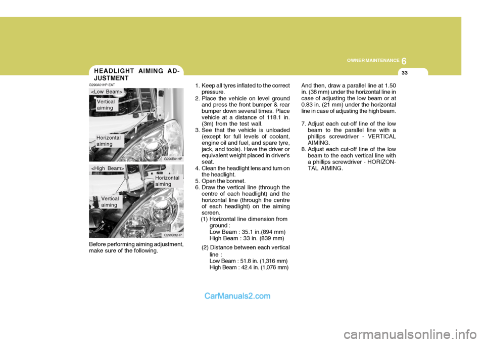
7. Adjust each cut-off line of the low beam to the parallel line with a phillips screwdriver - VERTICAL AIMING.
8. Adjust each cut-off line of the low beam to the each vertical line witha phillips screwdriver - HORIZON-TAL AIMING.
Before performing aiming adjustment,make sure of the following.HEADLIGHT AIMING AD- JUSTMENT
G290A01HP-EAT
1. Keep all tyres inflated to the correct
pressure.
2. Place the vehicle on level ground and press the front bumper & rear bumper down several times. Placevehicle at a distance of 118.1 in. (3m) from the test wall.
3. See that the vehicle is unloaded (except for full levels of coolant, engine oil and fuel, and spare tyre,jack, and tools). Have the driver or equivalent weight placed in driver's seat.
4. Clean the headlight lens and turn on the headlight.
5. Open the bonnet.
6. Draw the vertical line (through the centre of each headlight) and thehorizontal line (through the centre of each headlight) on the aiming screen.
(1) Horizontal line dimension from
Horizontal aiming
Vertical aiming
G290B01HP
G290B02HP
Horizontal aiming
Vertical aiming
ground : Low Beam : 35.1 in.(894 mm) High Beam : 33 in. (839 mm)
(2) Distance between each vertical line :Low Beam : 51.8 in. (1,316 mm) High Beam : 42.4 in. (1,076 mm)
Page 513 of 539
6 OWNER MAINTENANCE
36
NO.1
NO. 2
NO. 3
NO.4
NO.5
NO. 6
NO. 7
NO. 8
NO. 9
NO. 10
NO. 11
NO. 12
DESCRIPTION
G200C01HP-EAT Engine Compartment (#1)
G200C01HP-E
NOTE: Not all fuse panel descriptions in this manual may be applicable to your vehicle. It is accurate at the time of printing. When you inspect the fuse box on your vehicle, refer to the fuse box label. AMPERAGES
100A
120A (DIESEL)
140A ( PETROL)
50A 30A - -
20A 10A 15A -
10A10A CIRCUIT PROTECTED
Glow Relay (COVEC-F/EGR), Air Heater Relay (Diesel Engine) Engine Compartment Fuse & Relay Box #2,GeneratorInner Panel Fuse Box (Fuse 1,2,3,4,5)Engine Compartment Fuse & Relay Box #1 (Fuse 8,9)
Fuel Heater Control Module (COVEC-F/EGR)
Generator, Ignition Switch--Engine Control Relay (Diesel Engine), Main Control Relay
(Petrol Engine)
Horn Relay
Front Fog Lamp Relay-ECM (Diesel Engine), EGR Control ModuleECM (Diesel Engine)
FUSIBLE LINK
FUSE
FUSE PANEL DESCRIPTION
Petrol Engine Diesel Engine
Page 515 of 539
6 OWNER MAINTENANCE
38
AMPERAGES15A 15A15A-
10A 10A
-
15A 15A15A15A 10A 10A10A 10A 10A 10A15A25A20A
NO. 10 NO. 11NO. 12NO. 13NO. 14NO. 15NO. 16NO. 17NO. 18NO. 19NO. 20NO. 21NO. 22NO. 23
NO. 24
NO. 25
NO. 26
NO. 27
NO. 28
NO. 29
DESCRIPTION
CIRCUIT PROTECTED
Fuel Heater and Sensor(Diesel Engine)
Headlamp(Low beam)Headlamp(High beam) -
A/C Compressor Relay, Triple Switch
TCI Fan Relay(COVEC-F/EGR)--ECM(Diesel Engine)ECM(Diesel Engine)
ECM(Diesel Engine), Air Heater Relay(Diesel Engine), EGR Solenoid(Diesel Engine)
Illuminations, Combination LampLicense Lamp, Combination Lamp
ABS Control Module, ABS Relay, EBD Relay
ECM(Diesel Engine), Headlamp Relay, Condenser Fan Relay
(Petrol/COVEC-F), EGR Solenoid(COVEC-F)ABS Control Module
Cruise Control Module
Front Wiper and Washer
Power Seat Switch
Power Outlet Relay
FUSE
Page 516 of 539
6
OWNER MAINTENANCE
39
AMPERAGES 50A 30A 40A 40A 30A 40A 20A-
20A 10A
15A
NO. 1
NO. 2
NO. 3
NO. 4
NO. 5
NO. 6
NO. 7
NO. 8
NO. 9
DESCRIPTION
CIRCUIT PROTECTED
Power Connector(A,B), Engine Compartment Fuse and Relay #2
(Fuse 28,29), Inner Panel Fuse Box(Fuse 6,7,8, 9)
Start Relay, Ignition Switch
Condenser Fan Relay, Engine Compar tment Fuse and Relay Box #2(Fuse 14,15)ABS Control Module
Power Window Relay
Tail Lamp Relay, Engine Compartment Fuse and Relay Box #2(Fuse 11,12)ABS Control Module-
Fuel Pump Relay, ECM, Ignition Failure Sensor
A/CON, TCM, ETACM, Data Link Connector, Siren, ImmobiliserControl Module
Interior Lamp, Map Lamp, Audio, Instrument Cluster, Front Door EdgeWarning Lamp
FUSIBLE LINK
NO. 30
NO. 31
Page 520 of 539
7
EMISSION CONTROL SYSTEMS
3
DH010B1-E
1. Crankcase Emission Control System ; For a Petrol Engine
The positive crankcase ventilation
system is employed to prevent air pollution caused by blow-by gases being emitted from the crankcase.
This system supplies fresh air to the
crankcase through the air cleaner.Inside the crankcase, the fresh airmixes with blow-by gases, then passes through the PCV valve into the intake system.
ZH010C1-E
2. Evaporative Emission Control System ; For a Petrol Engine
The Evaporative Emission Control
System is designed to prevent fuel vapors from escaping into the atmo-sphere. Canister
Whilst the engine is inoperative, fuel
vapors generated inside the fuel tankare absorbed and stored in the canis-ter. When the engine is running, the fuel vapors absorbed in the canister are drawn into the induction systemthrough the purge control solenoid valve. Purge Control Solenoid Valve
The purge control solenoid valve is
controlled by the ECU; when the en- gine coolant temperature is low, and during idling, it closes, so that evapo- rated fuel is not taken into the surgetank. After engine warm-up, during ordinary driving, it opens to introduce evaporated fuel to the surge tank.
SH010D1-E
3. Exhaust Emission Control System
The exhaust emission control system
is a highly effective system which controls exhaust emission while main- taining good vehicle performance.
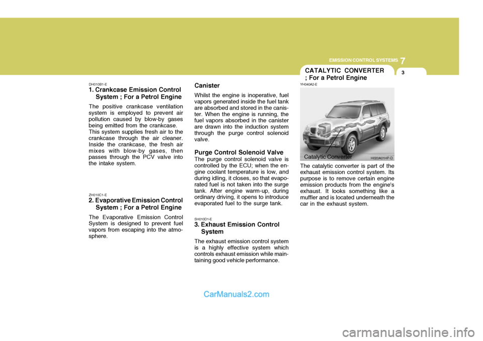
Catalytic Converter H020A01HP-D
CATALYTIC CONVERTER ; For a Petrol Engine
YH040A2-E The catalytic converter is part of the exhaust emission control system. Its purpose is to remove certain engineemission products from the engine's exhaust. It looks something like a muffler and is located underneath thecar in the exhaust system.
Page 521 of 539
7EMISSION CONTROL SYSTEMS
4
YH040B1-E About the Catalytic Converter ; For a Petrol Engine Exhaust gases passing through the catalytic converter cause it to operate at very high temperatures. As a re- sult, the introduction of large amountsof unburned petrol may cause it to overheat and create a fire hazard. This can be avoided by observing thefollowing: H020D01HP-GAT
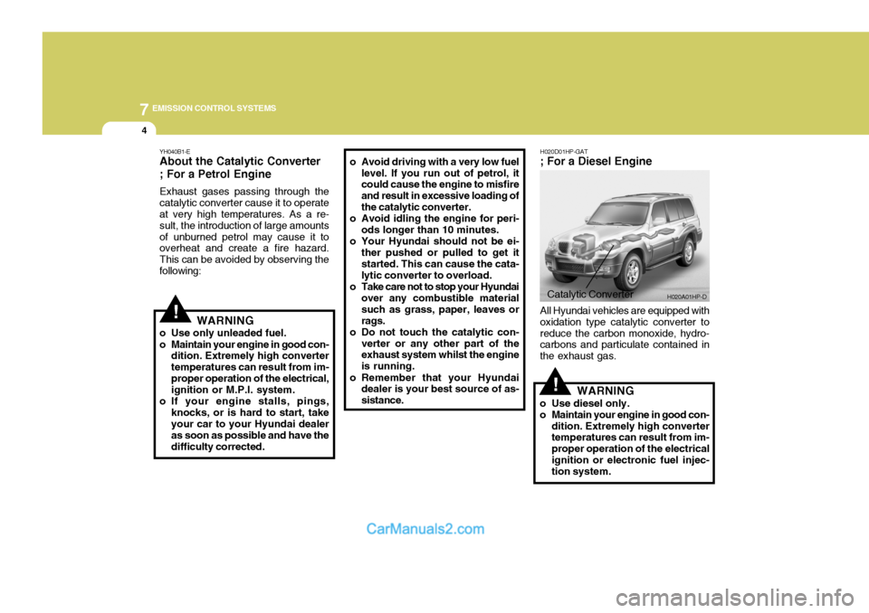
; For a Diesel Engine
!WARNING
o Use only unleaded fuel.
o Maintain your engine in good con- dition. Extremely high converter temperatures can result from im-proper operation of the electrical, ignition or M.P.I. system.
o If your engine stalls, pings, knocks, or is hard to start, takeyour car to your Hyundai dealer as soon as possible and have thedifficulty corrected. o Avoid driving with a very low fuel
level. If you run out of petrol, it could cause the engine to misfire and result in excessive loading ofthe catalytic converter.
o Avoid idling the engine for peri- ods longer than 10 minutes.
o Your Hyundai should not be ei- ther pushed or pulled to get itstarted. This can cause the cata- lytic converter to overload.
o Take care not to stop your Hyundai over any combustible material such as grass, paper, leaves orrags.
o Do not touch the catalytic con- verter or any other part of the exhaust system whilst the engine is running.
o Remember that your Hyundai dealer is your best source of as-sistance.
Catalytic Converter H020A01HP-D
!
All Hyundai vehicles are equipped with oxidation type catalytic converter toreduce the carbon monoxide, hydro- carbons and particulate contained in the exhaust gas.
WARNING
o Use diesel only.
o Maintain your engine in good con- dition. Extremely high converter temperatures can result from im- proper operation of the electricalignition or electronic fuel injec- tion system.