2005 Hyundai Sonata coolant
[x] Cancel search: coolantPage 208 of 271
6
DO-IT-YOURSELF MAINTENANCE
10
3. Be sure your drain receptacle is in place.
Open the drain cock on the radiator. Allow all
the engine coolant to drain from the cooling
system, and then securely close the drain
cock.
4. Check Section 9 for the capacity of the
cooling system in your car. Then, following
the manufacturer's directions on the engine
coolant container, add the appropriate quan-
tity of coolant to the radiator.
5. Slowly fill the radiator with the proper coolant
mixture (see the "Recommended Engine
Coolant in previous page) until the fluid level
stays up in the radiator neck. And pump the
radiator hose in order to bleed the air.
HNF5008
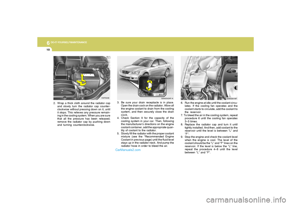
2. Wrap a thick cloth around the radiator cap
and slowly turn the radiator cap counter-
clockwise without pressing down on it, until
it stops. This relieves any pressure remain-
ing in the cooling system. When you are sure
that all the pressure has been released,
remove the radiator cap by pushing down
and turning counterclockwise.
G050D02NF-A
G050D01NF
6. Run the engine at idle until the coolant circu-
lates. If the cooling fan operates and the
coolant starts to circulate, add the coolant to
the reservoir.
7. To bleed the air in the cooling system, repeat
procedure 6 until the cooling fan operates
3~5 times.
8. Replace the radiator cap and turn it until
tightly installed. And then, add coolant to the
reservoir until the level is between "L" and
"F".
9. Stop the engine and check the coolant level
when the engine is cool. The level of the
coolant should be the "L" and "F" lines on the
reservoir. If the level is below the "L" line,
repeat the procedure 4~8 until the level
between "L" and "F".
Page 209 of 271

6
DO-IT-YOURSELF MAINTENANCE
11
!!
10.Replace the reservoir cap and check to be
sure the drain cock and the radiator cap are
fully closed and not leaking.
CAUTION:
Recheck after a few days and add the cool-
ant if the level is below the "L" level.
WARNING:
The cooling fan is controlled by engine
coolant temperature and may sometimes
operate even when the engine is not run-
ning. Use extreme caution when working
near the blades of the coolant fan so that
you are not injured by a rotating fan blade.
As the engine coolant temperature de-
creases, the fan will automatically shut off.
This is a normal condition.
Type
SK16PR-A11
IFR5G-11
SPARK PLUGSG060A01NF-AAT
G060A01LYour engine was originally equipped with Iri-
dium-tipped spark plugs.
Iridium-tipped spark plugs will last longer than
conventional type spark plugs and can be
identified by blue lines on the ceramic shell.NOTE:Do not clean or regap Iridium-tipped spark
plugs.
G060B01NF-AATReplacing the Spark PlugsThe spark plugs should be changed at the
intervals specified in the vehicle maintenance
schedule in Section 5 or whenever engine
performance indicates they should be changed.
Symptoms that suggest poor spark plug perfor-
mance include engine misfiring under load, loss
of fuel economy, poor acceleration, etc. When
spark plugs are replaced, always use spark
plugs recommended by Hyundai. The use of
other spark plugs can result in loss of perfor-
mance, radio interference or engine damage.NOTE:When replacing the spark plugs, always use
the genuine parts recommended.Recommended Spark Plugs:
0.039 ~ 0.043 in.
(1.0~1.1 mm)
Remark
2.4L
3.3L
Page 215 of 271
6
DO-IT-YOURSELF MAINTENANCE
17
CAUTION:
o Radiator antifreeze (engine coolant)
should not be used in the washer system
because it will damage the car's finish.
o The washer lever should not be pulled
and the washer should not be operated
if the washer reservoir is empty. This can
damage the washer fluid pump.
!
A good quality washer fluid should be used to fill
the washer reservoir. The fluid level should be
checked more frequently during bad weather or
whenever the washer system is in more fre-
quent use.
The capacity of the washer reservoir is 3.2 U.S.
quarts (4.0 liters).
!
WARNING:
It is always better to check the transaxle oil
level when the engine is cool or cold. If the
engine is hot, you should exercise great
caution to avoid burning yourself on hot
engine or exhaust parts.
CHECKING THE TRANSAXLE OIL
(MANUAL)G100A01NF-AAT
HNF5010
Filler plug
Drain plug
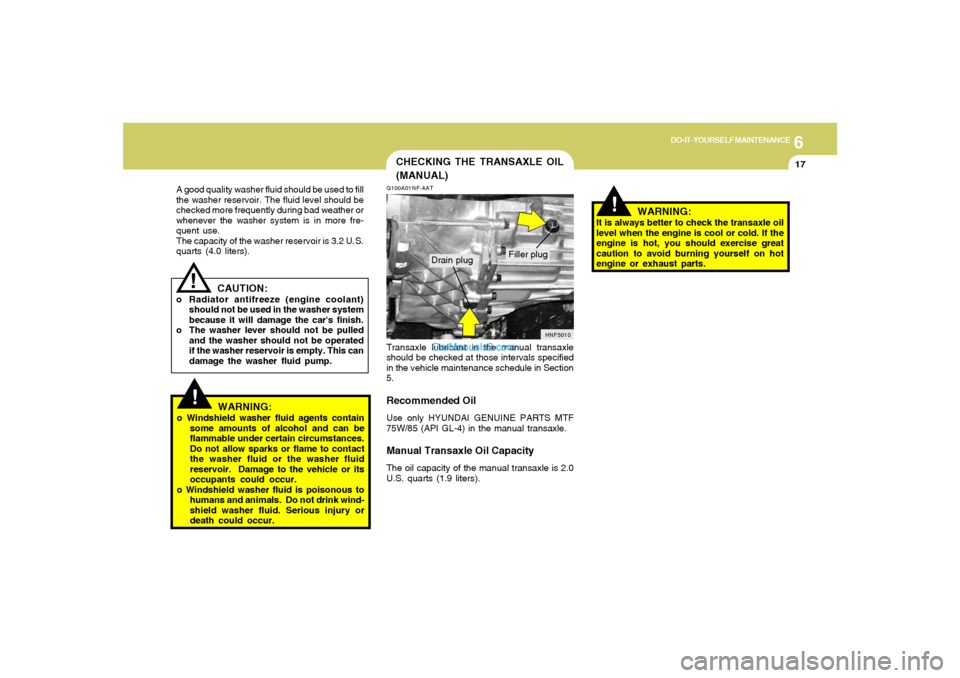
Transaxle lubricant in the manual transaxle
should be checked at those intervals specified
in the vehicle maintenance schedule in Section
5.Recommended OilUse only HYUNDAI GENUINE PARTS MTF
75W/85 (API GL-4) in the manual transaxle.Manual Transaxle Oil CapacityThe oil capacity of the manual transaxle is 2.0
U.S. quarts (1.9 liters).
!
WARNING:
o Windshield washer fluid agents contain
some amounts of alcohol and can be
flammable under certain circumstances.
Do not allow sparks or flame to contact
the washer fluid or the washer fluid
reservoir. Damage to the vehicle or its
occupants could occur.
o Windshield washer fluid is poisonous to
humans and animals. Do not drink wind-
shield washer fluid. Serious injury or
death could occur.
Page 218 of 271
6
DO-IT-YOURSELF MAINTENANCE
20
G110D02NF
CHECKING THE BRAKES!
G120B01A-AATChecking the Brake Fluid Level
WARNING:Use caution when handling brake fluid. It
can damage your vision if it gets into your
eyes. It will also damage your vehicle's
paint if spilled on it and not removed imme-
diately.
!
WARNING:
The cooling fan is controlled by engine
coolant temperature and may sometimes
operate even when the engine is not run-
ning. Use extreme caution when working
near the blades of the cooling fan so that
you are not injured by a rotating fan blade.
As the engine coolant temperature de-
creases, the fan will automatically shut off.
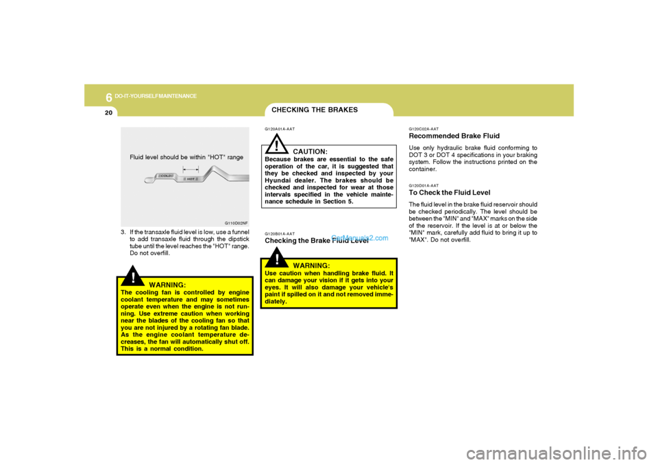
This is a normal condition.Fluid level should be within "HOT" range
G120A01A-AAT
CAUTION:
Because brakes are essential to the safe
operation of the car, it is suggested that
they be checked and inspected by your
Hyundai dealer. The brakes should be
checked and inspected for wear at those
intervals specified in the vehicle mainte-
nance schedule in Section 5.
!
3. If the transaxle fluid level is low, use a funnel
to add transaxle fluid through the dipstick
tube until the level reaches the "HOT" range.
Do not overfill.
G120D01A-AATTo Check the Fluid LevelThe fluid level in the brake fluid reservoir should
be checked periodically. The level should be
between the "MIN" and "MAX" marks on the side
of the reservoir. If the level is at or below the
"MIN" mark, carefully add fluid to bring it up to
"MAX". Do not overfill.G120C02A-AATRecommended Brake FluidUse only hydraulic brake fluid conforming to
DOT 3 or DOT 4 specifications in your braking
system. Follow the instructions printed on the
container.
Page 226 of 271
6
DO-IT-YOURSELF MAINTENANCE
28
!
!
WARNING:Always read the following in-
structions carefully when han-
dling a battery.
Keep lighted cigarettes and all
other flames or sparks away from
the battery.
Hydrogen, which is a highly com-
bustible gas, is always present in
battery cells and may explode if
ignited.
Keep batteries out of the reach of
children because batteries con-
tain highly corrosive SULFURIC
ACID. Do not allow battery acid
to contact your skin, eyes, cloth-
ing or paint finish.
If any electrolyte gets into your
eyes, flush your eyes with clean
water for at least 15 minutes and
get immediate medical attention.
If possible, continue to apply
water with a sponge or cloth until
medical attention is received.If electrolyte gets on your skin,
thoroughly wash the contacted
area.
If you feel a pain or a burning
sensation, get medical attention
immediately.
Wear eye protection when charg-
ing or working near a battery.
Always provide ventilation when
working in an enclosed space.
o When lifting a plastic-cased battery, ex-
cessive pressure on the case may cause
battery acid to leak, resulting in personal
injury. Lift with a battery carrier or with
your hands on opposite corners.
o Never attempt to charge the battery when
the battery cables are connected.
o The electrical ignition system works with
high voltage.
Never touch these components with the
engine running or the ignition switched
on.
WARNING:
CHECKING ELECTRIC COOLING
FANS!
G220A01A-AAT
WARNING:
The cooling fan is controlled by engine
coolant temperature and may sometimes
operate even when the engine is not run-
ning. Use extreme caution when working
near the blades of the cooling fan, so that
you are not injured by a rotating fan blade.
As the engine coolant temperature de-
creases the fan will automatically shut off.
This is a normal condition.G220B01NF-GATChecking Engine Cooling FanThe engine cooling fan should come on auto-
matically if the engine coolant temperature is
high or whenever the air conditioning is in
operation.
Page 228 of 271

6
DO-IT-YOURSELF MAINTENANCE
30
HEADLIGHT AIMING ADJUSTMENTG290A02O-AATBefore performing aiming adjustment, make
sure of the following.
1. Keep all tires inflated to the correct pressure.
2. Place the vehicle on level ground and press
the front bumper & rear bumper down sev-
eral times.
Place vehicle at a distance of 118 in. (3m)
from the test wall.
3. See that the vehicle is unloaded (except for
full levels of coolant, engine oil and fuel, and
spare tire, jack, and tools). Have the driver
or equivalent weight placed in driver's seat.
4. Clean the headlight lenses and turn on the
headlights (Low beam).
5. Open the hood.
G290A01NF-A
Vertical
aiming
!
6. Draw a vertical line (through the center of
each headlight beam pattern) and a horizon-
tal line (through the center of each headlight
beam pattern) on the aiming screen.
And then, draw a parallel line at 0.8 in. (21
mm) under the horizontal line.
7. Adjust each cut-off line of the low beam to the
parallel line with a phillips screwdriver -
VERTICAL AIMING.
WARNING:
Horizontal aiming should be adjusted by
an authorized Hyundai dealer.
G290B01NF-AATAdjustment After Headlight Assembly
Replacement
G260B01GK
L
W
H
H
Cut-off line
Ground line
"P"
Horizontal line
Vertical line
0.8 in.(21 mm)
If the vehicle has had front body repair and the
headlight assembly has been replaced, the
headlight aiming should be checked using the
aiming screen as shown in the illustration. Turn
on the headlight switch (Low Beam Position).
1. Adjust headlights so that main axis of light is
parallel to the center line of the body and is
aligned with point "P" shown in the illustration.
2. Dotted lines in the illustration show the center
of the headlights.
Page 243 of 271
7
EMISSION CONTROL SYSTEMS2
EMISSION CONTROL
SYSTEMS
H010B01A-AAT1. Crankcase Emission Control SystemThe positive crankcase ventilation system is
employed to prevent air pollution caused by
blow-by gases being emitted from the crank-
case. This system supplies fresh filtered air to
the crankcase through the air intake hose.
Inside the crankcase, the fresh air mixes with
blow-by gases, which then pass through the
PCV valve into the induction system.
CanisterFuel vapors generated inside the fuel tank are
absorbed and stored in the onboard canister.
When the engine is running, the fuel vapors
absorbed in the canister are drawn into the
surge tank through the purge control solenoid
valve.Purge Control Solenoid Valve (PCSV)The purge control solenoid valve is controlled
by the Engine Control Module (ECM); when the
engine coolant temperature is low during idling,
the PCSV closes so that evaporated fuel is not
taken into the engine. After the engine warms-
up during ordinary driving, the PCSV opens to
introduce evaporated fuel to the engine.H010D01A-AAT3. Exhaust Emission Control
SystemThe Exhaust Emission Control System is a
highly effective system which controls exhaust
emissions while maintaining good vehicle per-
formance.
H010A01NF-AATYour Hyundai is equipped with an emission
control system to meet all emission regulations.
There are three emission control systems which
are as follows.
(1) Crankcase emission control system
(2) Evaporative emission control system
(3) Exhaust emission control system
In order to assure the proper function of the
emission control systems, it is recommended
that you have your car inspected and main-
tained by an authorized Hyundai dealer in ac-
cordance with the maintenance schedule in this
manual.
Caution for the Inspection and Maintenance
Test (With Electronic Stability Control (ESC)
system)
o To prevent the vehicle from misfiring
during dynamometer testing, turn the
Electronic Stability Control (ESC) sys-
tem off by pressing the ESC switch.
o After dynamometer testing is completed,
turn the ESC system back on by pressing
the ESC switch again.
H010C01S-AAT2. Evaporative Emission Control (Includ-
ing ORVR: Onboard Refueling Vapor
Recovery) SystemThe Evaporative Emission Control System is
designed to prevent fuel vapors from escaping
into the atmosphere.
(The ORVR system is designed to allow the
vapors from the fuel tank to be loaded into a
canister while refueling at the gas station, pre-
venting the escape of fuel vapors into the
atmosphere.)
Page 250 of 271

8
CONSUMER INFORMATION, REPORTING SAFETY DEFECTS & BINDING ARBITRATION OF WARRANTY CLAIMS6
6. Maximum load rating
This number indicates the maximum
load in kilograms and pounds that
can be carried by the tire. When
replacing the tires on the vehicle,
always use a tire that has the same
load rating as the factory installed
tire.
7. Uniform Tire Quality Grading
(UTQG):
Tire manufacturers are required to
grade tires based on three perfor-
mance factors: treadwear, traction
and temperature resistance. For more
information, see Uniform Tire Qual-
ity Grading on page 8-13.
I030D01JM-AATTIRE TERMINOLOGY AND DEFINI-
TIONS
Air Pressure: The amount of air inside
the tire pressing outward on the tire. Air
pressure is expressed in pounds per
square inch (psi) or kilopascal (kPa).
Accessory Weight: This means the
combined weight of optional accesso-
ries. Some examples of optional ac-
cessories are, automatic transmission,
power seats, and air conditioning.
Aspect Ratio: The relationship of a
tire's height to its width.
Belt: A rubber coated layer of cords that
is located between the plies and the
tread. Cords may be made from steel or
other reinforcing materials.
Bead: The tire bead contains steel
wires wrapped by steel cords that hold
the tire onto the rim.
Bias Ply Tire: A pneumatic tire in which
the plies are laid at alternate angles
less than 90 degrees to the centerline of
the tread.Cold Tire Pressure: The amount of air
pressure in a tire, measured in pounds
per square inch (psi) or kilopascals
(kPa) before a tire has built up heat from
driving.
Curb Weight: This means the weight of
a motor vehicle with standard and op-
tional equipment including the maxi-
mum capacity of fuel, oil and coolant,
but without passengers and cargo.
DOT Markings: A code molded into the
sidewall of a tire signifying that the tire
is in compliance with the U.S. Depart-
ment of Transportation motor vehicle
safety standards. The DOT code in-
cludes the Tire Identification Number
(TIN), an alphanumeric designator which
can also identify the tire manufacturer,
production plant, brand and date of
production.
GVWR: Gross Vehicle Weight Rating
GAWR FRT: Gross Axle Weight Rating
for the front Axle.
GAWR RR: Gross Axle Weight Rating
for the rear axle.