2005 Hyundai Matrix horn
[x] Cancel search: hornPage 14 of 407

CONTROLS AND EQUIPMENT
1- 6 The system will be disarmed when the driver's or passenger's door is unlocked by depress-ing the "UNLOCK" button on the transmitter. After completion of the step above, the turn signal light will blink twice to indicate that thesystem is disarmed. NOTE: Once the system has been disarmed, it can not be rearmed except by repeating thearming procedures. CAUTION: Only the transmitter can disarm the armed stage. If the transmitter does not disarmthe system, it is necessary to take thefollowing steps;
1. Unlock the door with the key, which will
cause, the alarm to be activated.
2. Insert the key in the ignition key cylin- der and turn the ignition key to "ON" position.
3. Wait for 30 seconds. After completion of the steps above, the system will be disarmed. B070F01A-EAT Keyless Entry System (Not all models) Locking doors
1. Close all doors.
2. Push the "LOCK" button on the transmit-
ter.
3. At the same time all doors lock, the turn signal light will blink once to indicate that the system is armed.
Unlocking doors
1. Push the "UNLOCK" button on the trans- mitter.
2. At the same time all doors unlock, the turn signal light will blink twice to indicate that the system is disarmed.
B070E02HP-GAT Replacing the batteryWhen the transmitter's battery begins to get weak, it may take several pushes on thebutton to lock or unlock the doors, and theLED will not light. Replace the battery as soonas possible. Battery type : CR2032
B070C01FC-EAT Alarm Stage The alarm will be activated if any of the following occurs whilst the car is parked andthe system is armed.
1) A front or rear door is opened without using
the transmitter.
2) The tail gate is opened without using the transmitter.
3) The engine bonnet is opened.The alarming horn will sound and the turn signal lights will blink continuously for 27seconds. To turn off the system, unlock thedoor or tail gate with the transmitter.
B070D02O-AAT Disarmed Stage
3A9BA21
Page 37 of 407

1- 29
CONTROLS AND EQUIPMENTHFC002-D
B250A01FC-EAT INSTRUMENTS AND CONTROLS
1. Passenger's Side Drink Holder
2. Passenger's Airbag
3. Accessory Tray
4. Heating/Air Conditioning Control Panel(Not all models)
5. Hazard Warning Light
6. Instrument Cluster
7. Windscreen Wiper/Washer Switch
8. Horn and Driver's Airbag
9. Indicator and Warning Light
10. Multi-Function Light Switch
11. Front Fog Light Switch (Not all models)
12. Headlight Leveling Switch
13. Rear Fog Light Switch
14. Glove Box
15. Centre Console (Not all models)
16. Parking Brake Lever
17. Drink Holder
18. Shift Lever (Not all models)
19. Cigar Lighter
20. Ashtray
21. Multi Box
22. Bonnet Release Lever
CAUTION: When installing a container of liquid air freshener inside a vehicle, do not place it near the instrument cluster nor on the instrument panel pad surface.If there is any leakage from the air freshener onto these areas (instrument cluster, instrumentpanel pad or air ventilator), it may damage these parts. If the liquid from the air freshener does leak onto these areas, wash them with water immediately. 1
2
34 5
67
89 1011
1213
14 15 1617
1819
20 2122
Page 62 of 407

CONTROLS AND EQUIPMENT
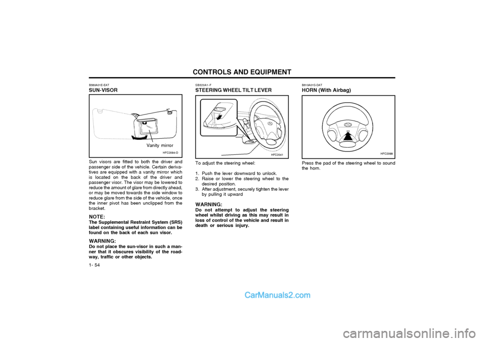
1- 54 B610A01S-DAT HORN (With Airbag) Press the pad of the steering wheel to sound the horn.
B580A01E-EAT
SUN-VISOR
Sun visors are fitted to both the driver and
passenger side of the vehicle. Certain deriva-tives are equipped with a vanity mirror whichis located on the back of the driver andpassenger visor. The visor may be lowered toreduce the amount of glare from directly ahead,or may be moved towards the side window toreduce glare from the side of the vehicle, oncethe inner pivot has been unclipped from thebracket.
NOTE: The Supplemental Restraint System (SRS)
label containing useful information can be found on the back of each sun visor.
WARNING: Do not place the sun-visor in such a man-
ner that it obscures visibility of the road- way, traffic or other objects. SB520A1-F
STEERING WHEEL TILT LEVER
HFC2099HFC2041HFC2094-D
Vanity mirror
To adjust the steering wheel:
1. Push the lever downward to unlock.
2. Raise or lower the steering wheel to the
desired position.
3. After adjustment, securely tighten the lever by pulling it upward
WARNING: Do not attempt to adjust the steeringwheel whilst driving as this may result inloss of control of the vehicle and result indeath or serious injury.
Page 111 of 407

OWNER MAINTENANCE
6-4 SG020B1-E
DAILY OPERATING CHECKS
The following items should be checked on a
daily basis or whenever the vehicle is refuelled, whichever occurs sooner.
o Engine oil level.
o Engine coolant level.
o Power steering fluid level.
o Brake fluid level.
o Windscreen washer fluid level.
o Battery condition.
o Tyre condition and pressures.
o Operation and cleanliness of all lighting equipment.
o Windscreen wiper and washer operation.
o Horn operation.
o Warning light operation.
o Adjustment and cleanliness of mirrors.
o Seat and seat belt adjustment and opera- tion.
o Fluid leakage.
The vehicle must not be driven if the daily
operating checks indicate that any item of equip- ment related to the safety or roadworthiness ofthe vehicle is not functioning correctly. G030A01FC-EAT
ENGINE OIL
The correct engine oil level is of paramount
importance. An excessively high or low oil levelmay result in irreparable damage being sus-tained by the engine. The engine oil levelmust be checked on a daily basis, wheneverthe vehicle is refuelled or before starting along trip, whichever occurs sooner.
In addition, it is imperative that only an ap-
proved grade and specification of oil is used toavoid the possibility of serious engine damageand premature wear. The use of "budget price"oil is a false economy that must be avoided ifthe maximum reliability and useful life is to beobtained from the vehicle. G030B02O-EAT
Recommended Oil
1. Petrol engine
G030B01FC
The engine oil quality should meet the follow- ing classification. API SJ, SL or ABOVE, ILSAC GF-3 or ABOVE The oil viscosity should be selected accord- ing to the operating environment of the engineby means of the table shown above. Theengine oil recommendations are complete inthemselves and the use of additives is neitherrequired nor recommended. The use of en-gine oil additives may result in invalidation ofthe vehicle warranty.
Page 135 of 407

OWNER MAINTENANCE
6-28
G200C01FC-EAT
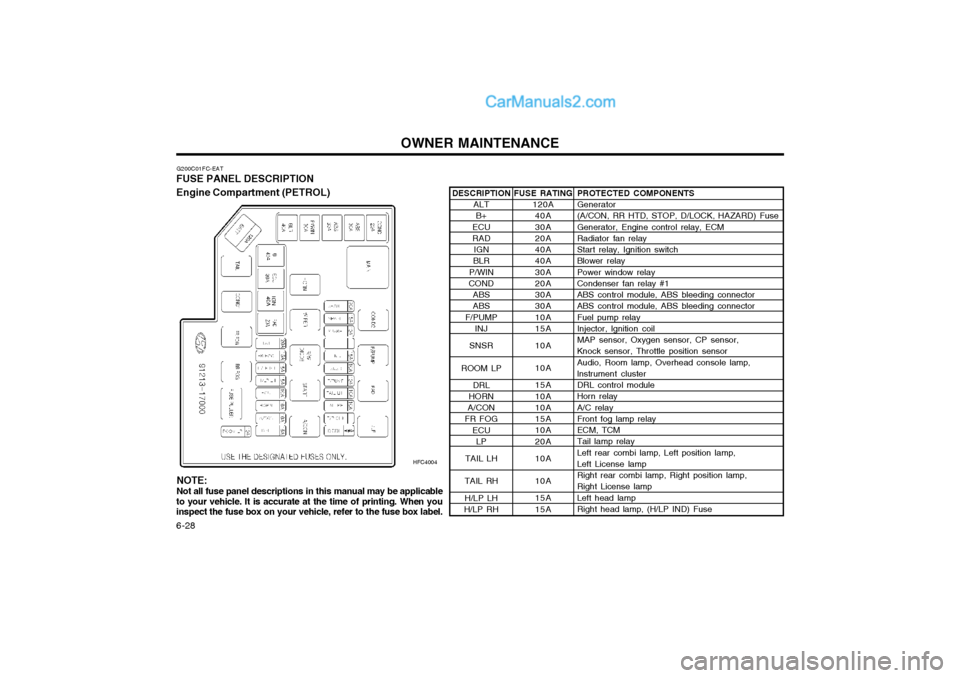
FUSE PANEL DESCRIPTION Engine Compartment (PETROL)
HFC4004PROTECTED COMPONENTS Generator (A/CON, RR HTD, STOP, D/LOCK, HAZARD) Fuse Generator, Engine control relay, ECM Radiator fan relay Start relay, Ignition switch Blower relay Power window relay Condenser fan relay #1 ABS control module, ABS bleeding connector ABS control module, ABS bleeding connector Fuel pump relay Injector, lgnition coil MAP sensor, Oxygen sensor, CP sensor, Knock sensor, Throttle position sensor Audio, Room lamp, Overhead console lamp, lnstrument cluster DRL control module Horn relay A/C relay Front fog lamp relay ECM, TCM Tail lamp relay Left rear combi lamp, Left position lamp, Left License lamp Right rear combi lamp, Right position lamp, Right License lamp Left head lamp Right head lamp, (H/LP IND) Fuse
FUSE RATING
120A40A 30A 20A 40A 40A 30A 20A 30A 30A 10A 15A 10A 10A 15A 10A 10A 15A 10A 20A 10A 10A 15A 15A
DESCRIPTION
ALTB+
ECU RAD IGN
BLR
P/WIN
COND
ABSABS
F/PUMP INJ
SNSR
ROOM LP DRL
HORN
A/CON
FR FOG
ECULP
TAIL LH
TAIL RH H/LP LH
H/LP RH
NOTE: Not all fuse panel descriptions in this manual may be applicable
to your vehicle. It is accurate at the time of printing. When you inspect the fuse box on your vehicle, refer to the fuse box label.
Page 137 of 407

OWNER MAINTENANCE
6-30
PROTECTED COMPONENTS
Generator (A/CON, RR HTD, STOP, D/LOCK, HAZARD) Fuse, DeicerGenerator, Engine control relay, ECMRadiator fan relay Start relay, Ignition switch Blower relayPower window relayCondenser fan relay #1ABS control module, ABS bleeding connectorABS control module, ABS bleeding connector Fuel pump relay ECM No.5 (Batt+)ECM No.4 (Batt+), Stop lamp switch, PTC heater relay #1Glow plug relay, Assistor heater relay 1/2, Stop lamp switch,TDC sensor, EGR act, Throttle plate act, VGT vacuum Audio, Room lamp, Overhead console lamp, lnstrument cluster, ETACM, Luggage lamp DRL control moduleHorn relayA/C relayFront fog lamp relayECM, TCM Tail lamp relay Left rear combi lamp, Left position lamp, Left License lampRight rear combi lamp, Right position lamp, Right License lampLeft head lampRight head lamp, (H/LP IND) FusePTC heater relay #1 GLOW relay PTC heater relay #2FFHS relayPTC heater relay #3
FUSE RATING
140A40A 30A 30A40A40A30A30A 30A 30A10A30A10A 15A10A 15A10A 10A 15A10A20A10A10A 15A 15A40A80A40A30A 40A
ALT
B+
ECU RAD
IGN
BLR
P/WIN COND ABSABS
F/PUMP ECUECU
SNSR
ROOM LP DRL
HORN
A/CON
FR FOG ECULP
TAIL LH
TAIL RH H/LP LH
H/LP RH
PTC HTR 1 GLOW
PTC HTR 2 FFHS
PTC HTR 3
FUSE
FUSIBLE LINK DESCRIPTION
Page 148 of 407

INDEX
10-2
E EFFECTIVE BRAKING
...................................................................... 2-9
ELECTRIC COOLING FANS ........................................................... 6-22
EMERGENCY TOWING ................... ...............................................3-10
EMISSION CONTROL SYSTEM ...................................................... 7-1
ENGINE COMPARTMENT ...................................................... 6-1 ~ 6-3
ENGINE COOLANT CHECKING AND REPLACING ....................... 6-9
ENGINE OIL AND FILTER REPLACEMENT ................................... 6-6
ENGINE OIL CONSUMPTION .......................................................... 6-6
ENGINE OIL REPLENISHMENT ...................................................... 6-5
ENGINE OIL ....................................................................................... 6-4
EXTERIOR REAR VIEW MIRR OR ................................................. 1-47
FFOLDING REAR SEATBACK AND SEAT CUSHION .......1-11 ~ 1-12
FOLD-UP TRAY ............................................................................... 1-50
FRONT ASHTRAY ........................................................................... 1-42
FRONT FOG LIGHT SWITCH ........................................................ 1-41
FUEL ECONOMY .............................................................................. 2-4
FUEL GAUGE .................................................................................. 1-35
FUEL RECOMMENDATIONS ........................................................... 1-1
FUSE PANEL DESCRIPTION ......................................................... 6-28
FUSIBLE LINKS ............................................................................... 6-20G GLOVE BOX
.................................................................................... 1-47
H HAZARD WARNING SYSTEM ........................................................ 1-40
HEADLIGHT AIMING ADJUSTEMENT ..........................................6-25
HEADLIGHT BULB ......................................................................... 6-24
HEADLIGHT LEVELING DEVICE SYSTEM ..................................1-44
HEAD RESTRAINT ADJUSTMENT ........................................ 1-9, 1-11
HEATED REAR WINDOW .............................................................. 1-41
HEATING CONTROL ....................................................................... 1-58
HEIGHT ADJUSTABLE FRONT SEAT SHOULDER BELT .......... 1-14
HORN ............................................................................................... 1-54
I
IF THE ENGINE CANNOT BE CRANKED ...................................... 3-1
IF THE ENGINE WILL NOT START ................................................ 3-1
IF THE EVENT OF A PUNCTURE ................................................... 3-4
IF YOUR VEHICLE MUST BE TOWED ........................................... 3-8
IMMOBILISER SYSTEM ......................................................... 1-2 ~ 1-3
INDIVIDUAL CIRCUIT FUSES ........................................................ 6-21
INSTRUMENT CLUSTER AND INDICATORS .............................. 1-30
INSTRUMENTS AND CONTROLS .................................................1-29
INTERIOR LIGHT ............................................................................ 1-46
INTERIOR REAR VIEW MIRROR .................................................. 1-49
Page 161 of 407

1. Front Fog Light Switch (If installed)
2. Headlight Leveling Switch (If installed)
3. Rear Fog Light Switch (If installed)
4. Multi-Function Light Switch
5. Indicator and Warning Light
6. Horn and Driver's Airbag (If installed)
7. Windshield Wiper/Washer Switch
8. Instrument Cluster
9. Hazard Warning Light
10.Heating/Air Conditioning Control Panel (If installed)
11.Audio System (If installed)
12.Accessory TrayCAUTION:
When installing a container of liquid air freshener inside the vehicle, do not place it near the instrument cluster nor on the instrument panel pad surface. If there is any leakage from the air freshener onto these areas (instrument cluster, instrument panel pad or air ventilator), it may damage these parts. If the liquid from the air freshener does leak onto these areas, washthem with water immediately.
! 13.Passenger's Airbag (If installed)
14.Passenger's Drink Holder
15.Hood Release Lever
16.Multi Box
17.Ashtray
18.Cigarette Lighter
19.Shift Lever (If installed)
20.Drink Holder
21.Parking Brake Lever
22.Glove Box
23.Center Console (If installed)