2005 Hyundai H-1 (Grand Starex) fuel
[x] Cancel search: fuelPage 125 of 205

44IN CASE OF EMERGENCY
24
D010B01A-AAT If Engine Doesn't Turn Over or Turns Over Slowly
1. If your car has an automatic
transaxle, be sure the gear selector lever is in "N" or "P" and the emer-gency brake is set.
2. Check the battery connections to be
sure they are clean and tight.
3. Turn on the interior light. If the light dims or goes out when you operatethe starter, the battery is discharged.
4. Check the starter connections to be sure they are securely tightened.
5. Do not push or pull the vehicle to start it. See instructions for "Jump Starting". D010B02P
D010D01A-AAT If the Engine Stalls While Driving
1. Reduce your speed gradually, keep-ing a straight line. Move cautiously off the road to a safe place.
2. Turn on your emergency flashers.
3. Try to start the engine again. If your
vehicle will not start, contact a Hyundai dealer or seek other quali- fied assistance.
JUMP STARTING
!
HA1FL4001
WARNING:
The gas produced by the battery during the jump-start operation is highly explosive. If these instruc-tions are not followed exactly, seri- ous personal injury and damage to the vehicle may occur! If you arenot sure how to follow this proce- dure, seek qualified assistance. Automobile batteries contain sul-furic acid. This is poisonous and highly corrosive. When jump start- ing, wear protective glasses and becareful not to get acid on yourself, your clothing or on the car. E110A02P-GAT
Discharged battery
Booster battery
D010C01A-AAT If Engine Turns Over Normally but Does Not Start 1. Check fuel level. 2. With the key in the "OFF" position,check all connectors at ignition coils and spark plugs(For Gasoline En- gine) or check all connectors atglow plug and glow plug relay(For Diesel Engine). Reconnect any that may be disconnected or loose.
3. Check fuel line in the engine room. 4. If engine still refuses to start, call a
Hyundai dealer or seek other quali- fied assistance.
Page 127 of 205
44IN CASE OF EMERGENCY
26
4. Check to see if the water pump drivebelt is missing. If it is not missing, check to see that it is tight. If the drive belt seems to be satisfactory, check for engine coolant leakingfrom the radiator, hoses or under the car. (If the air conditioning had been in use, it is normal for coldwater to be draining from it when you stop).
!WARNING:
While the engine is running, keep hair, hands, long hair and clothing away from moving parts such as the fan and drive belts to preventinjury.
!WARNING (Diesel only):
Never work on injection system with engine running or within 30 sec- onds after shutting off engine. High pressure pump, rail, injectors andhigh pressure pipes are subject to high pressure even after the engine stopped. The fuel jet produced byfuel leaks may cause serious in- jury, if it touch the body. People using pacemakers should not movethan 30cm closer to the ECU or wiring harness within the engine room while engine is running, sincethe high currents in the Common Rail system produce considerable magnetic fields.
5. If the water pump drive belt is bro- ken or engine coolant is leaking out, stop the engine immediately and call the nearest Hyundai dealer for assistance.!WARNING:
Do not remove the radiator cap when the engine is hot. This can allow coolant to be blown out of the open- ing and cause serious burns.
6. If you cannot find the cause of the overheating, wait until the engine temperature has returned to nor-mal. Then, if the engine coolant has been lost, carefully add coolant to the reservoir (page 8-12) to bringthe fluid level in the reservoir up to the halfway mark.
7. Proceed with caution, keeping alert for further signs of overheating. Ifoverheating happens again, call a Hyundai dealer for assistance.
CAUTION:
Serious loss of engine coolant indi-cates there is a leak in the coolingsystem and this should be checked as soon as possible by a Hyundai dealer.
!
Page 130 of 205
4
CORROSION PREVENTION AND APPEARANCE CARE
29
4
IN CASE OF EMERGENCY
29
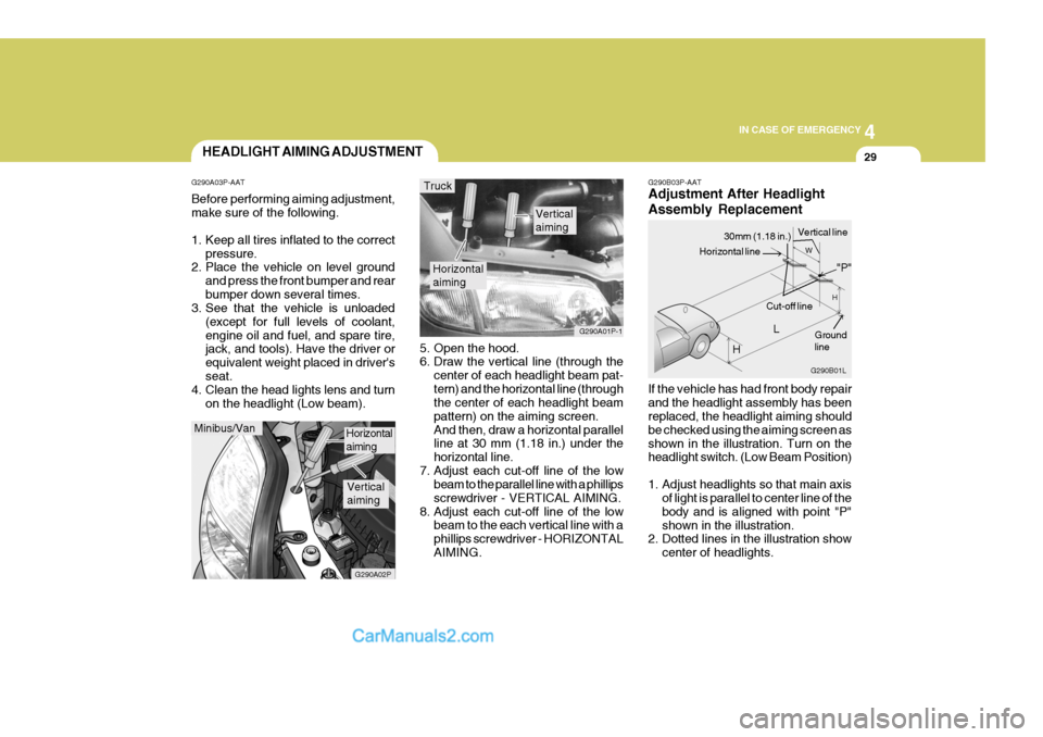
G290B03P-AAT Adjustment After Headlight Assembly Replacement If the vehicle has had front body repair and the headlight assembly has been replaced, the headlight aiming should be checked using the aiming screen asshown in the illustration. Turn on the headlight switch. (Low Beam Position)
1. Adjust headlights so that main axis
of light is parallel to center line of the body and is aligned with point "P"shown in the illustration.
2. Dotted lines in the illustration show
center of headlights.
5. Open the hood.
6. Draw the vertical line (through the
center of each headlight beam pat- tern) and the horizontal line (through the center of each headlight beam pattern) on the aiming screen.And then, draw a horizontal parallel line at 30 mm (1.18 in.) under the horizontal line.
7. Adjust each cut-off line of the low beam to the parallel line with a phillipsscrewdriver - VERTICAL AIMING.
8. Adjust each cut-off line of the low beam to the each vertical line with aphillips screwdriver - HORIZONTALAIMING.
Horizontal aiming
Verticalaiming
G290A01P-1
Truck
G290B01L
LW
H
H Cut-off line
Ground line
"P"
Horizontal line
30mm (1.18 in.) Vertical line
HEADLIGHT AIMING ADJUSTMENT
G290A03P-AAT Before performing aiming adjustment, make sure of the following.
1. Keep all tires inflated to the correct pressure.
2. Place the vehicle on level ground
and press the front bumper and rear bumper down several times.
3. See that the vehicle is unloaded
(except for full levels of coolant,engine oil and fuel, and spare tire, jack, and tools). Have the driver or equivalent weight placed in driver'sseat.
4. Clean the head lights lens and turn
on the headlight (Low beam).
Minibus/Van
G290A02P
Horizontal aiming
Verticalaiming
Page 141 of 205
44IN CASE OF EMERGENCY
40FUSE PANEL DESCRIPTION
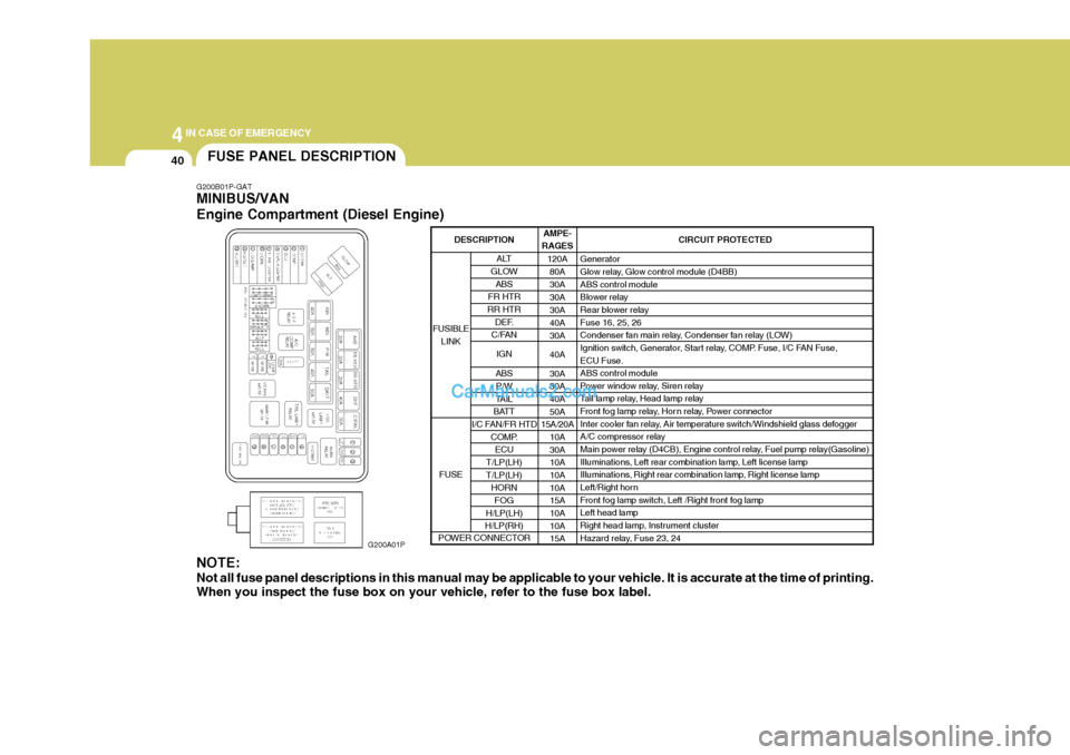
G200B01P-GAT MINIBUS/VAN Engine Compartment (Diesel Engine)
G200A01P
NOTE: Not all fuse panel descriptions in this manual may be applicable to your vehicle. It is accurate at the time of printing. When you inspect the fuse box on your vehicle, refer to the fuse box label. AMPE-
RAGES
120A80A 30A30A30A40A30A 40A30A 30A 40A 50A
15A/20A
10A30A10A 10A 10A15A 10A 10A15A CIRCUIT PROTECTED
Generator
Glow relay, Glow control module (D4BB) ABS control module
Blower relay
Rear blower relay Fuse 16, 25, 26
Condenser fan main relay, Condenser fan relay (LOW)
Ignition switch, Generator, Start relay, COMP. Fuse, I/C FAN Fuse, ECU Fuse. ABS control module
Power window relay, Siren relay
Tail lamp relay, Head lamp relay
Front fog lamp relay, Hor n relay, Power connector
Inter cooler fan relay, Air temperature switch/Windshield glass defogger
A/C compressor relay
Main power relay (D4CB), Engine control relay, Fuel pump relay(Gasoline)
Illuminations, Left rear combination lamp, Left license lamp
Illuminations, Right rear combination lamp, Right license lamp
Left/Right horn
Front fog lamp switch, Left /Right front fog lampLeft head lamp
Right head lamp, Instrument cluster
Hazard relay, Fuse 23, 24
ALT
GLOW ABS
FR HTR
RR HTR DEF.
C/FAN
IGN
ABS P/W
TAIL
BATT
I/C FAN/FR HTD COMP.
ECU
T/LP(LH) T/LP(LH) HORN
FOG
H/LP(LH)
H/LP(RH)
FUSIBLE
LINK
FUSE
DESCRIPTION
POWER CONNECTOR
Page 142 of 205
4
CORROSION PREVENTION AND APPEARANCE CARE
41
4
IN CASE OF EMERGENCY
41
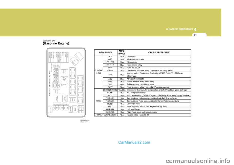
G200C01P-GAT (Gasoline Engine)
G200B01P AMPE-
RAGES
120A30A 30A30A40A30A 40A30A 30A 40A 50A
15A/20A
10A30A10A 10A 10A15A 10A 10A15A CIRCUIT PROTECTED
GeneratorABS control module
Blower relay
Rear blower relayFuse 16, 25, 26
Condenser fan main relay, Condenser fan relay (LOW)
Ignition switch, Generator, Start relay, COMP. Fuse,FR HTD Fuse,ECU Fuse. ABS control module
Power window relay, Siren relay
Tail lamp relay, Head lamp relay
Front fog lamp relay, Horn relay, Power connector
Inter cooler fan relay, Air temperature switch/Windshield glass defogger
A/C compressor relay
Main power relay (D4CB), Engine control relay, Fuel pump relay(Gasoline)
Illuminations, Left rear combination lamp, Left license lamp
Illuminations, Right rear combination lamp, Right license lamp
Left/Right horn
Front fog lamp switch, Left /Right front fog lamp Left head lamp
Right head lamp, Instrument cluster
Hazard relay, Fuse 23, 24
ALT
ABS
FR HTR
RR HTR
DEF.
C/FAN
IGN
ABS P/W
TAIL
BATT
I/C FAN/FR HTD
COMP.ECU
T/LP(LH) T/LP(LH) HORNFOG
H/LP(LH)
H/LP(RH)
FUSIBLE
LINK
FUSE
DESCRIPTION
POWER CONNECTOR
Page 143 of 205

44IN CASE OF EMERGENCY
42
G200D01P-GAT Inner Panel
G200D01PFUSE
1 23 4 56 7 8 9
10 11 12 13 14 15161718 19 20 CIRCUIT PROTECTED
Power outside mirror switch
Audio, Digital clock, Cigarette lighter, Multi-meter, A/T shift & key lock control module
Power outlet
Heater control module, Mode actuator
Front wiper & Washer
Rear wiper & Washer
Left front/rear sunroof relay, PTC heater relay, Fuel filter heater relay, Thermo sensor,
Hear lamp relay, Condenser fan main relay, HLLD switch, Inter cooler fan relay
ETACM, Power & hold switch, Front wiper relay, Seat belt tension reducer, Blower relay,
Overhead blower relay, Outside mirror defogger relay, Rear window defogger relay,
Rear blower relay, Rear blower main switch, Rear blower sub switch
Rear fog lamp relay
Seat warmer switchInstrument clusterSRS control module
ABS control module, Neutral switch, Back-up lamp switch, Vehicle speed sensor, Fuel
water sensor, Fuel filter switch, Fuel filter heater, Transaxle range switch, Instrument
cluster, TCM, Stop lamp switch, A/T shift & Key lock control module, G-Sensor, Overdrive
switch, A/T shift lever
Hazard switch
ETACM, ECM (D4BH), ECM (D4CB), Immobilizer control module, Idle-up control module
Rear window defogger relay
Left front sunroof relay
Left rear sunroof relay
Data link connector, Heater control module, Outside mirror defogger relay
Stop lamp switchAMPERAGES 10A 15A15A10A20A15A 10A 10A 10A 10A10A10A 10A10A 10A25A20A20A10A15A
Page 151 of 205
5
APPEARANCE CARE
5
F010P01P-GAT
Tire replacement
Tires which do not meet the size specifications must not be used. Re- placement of the tires must be made as a set of the two front tires, the tworear tires, or all four tires.A mixture of bias-ply tires and radialtires must not be used. Consult an authorized HYUNDAI dealer regarding tire replacement.
F010R01P-GAT
Tire care
For driving safely, and in order to
obtain the maximum useful life of thetires, the following points should be observed. For information concerning inspection, air pressure, and rotationof the tires, refer to the part which deals with wheels in the section of this manual entitled "Consumer Informa-tion". F010S01P-GAT
Tire air pressure
The air pressure of the tires mustalways be maintained in accordance with the specifications, and should be measured when the tires are cool.If any changes in driving conditions(speed and/or load weight) occur, theair pressure of the tires must meet the specifications which apply to the new driving conditions. If the vehicle isgoing to be driven under varying load weight, etc., the air pressure must be adjusted in order to meet the highestspecifications of the conditions under which the vehicle is driven (high speeds and maximum load weight). F010T01P-GAT Tire storage Storage of the tires should be in a dark, well-ventilated place.Tires not mounted on rims should bestored vertically. Be sure that the tires are not in contact with fuel, oil grease, etc.
Page 153 of 205

6VEHICLE MAINTENANCE REQUIREMENTS
2MAINTENANCE INTERVALS
F010C01A-GAT
Specified Scheduled Procedures
These are the procedures such as
inspections, adjustments and replace- ments that are listed in the mainte-nance charts starting on page 6-4. These procedures must be performed at the intervals shown in the mainte-nance schedule to assure that your warranty remains in effect. Although it is strongly recommended that they beperformed by the factory-trained or distributor-trained technicians at your Hyundai dealer, these procedures maybe performed at any qualified service facility. F010D01P-AAT
General Checks
These are the regular checks you should perform when you drive your Hyundai or you fill the fuel tank. A list of these items will be found on page8-6.
F010A01A-GAT Service Requirements To assure that you receive the great- est number of kilometers of satisfying operation from your Hyundai, certain maintenance procedures must be per-formed. Although careful design and engineering have reduced these to a minimum, those that are required areof the utmost importance.It is your responsibility to have thesemaintenance procedures performed to comply with the terms of the warran- ties covering your new Hyundai. TheService Passport supplied with your new vehicle provides further informa- tion about these warranties.
F010B01A-AAT
Maintenance Requirements
The maintenance required for your
Hyundai can be divided into three main areas: o Specified scheduled procedures o General checks o Do-it-yourself maintenance It is suggested that genuine Hyundai
service parts be used for any requiredrepairs or replacements. Other parts of equivalent quality such as engine oil, engine coolant, manual or autotransaxle oil, brake fluid and so on which are not supplied by Hyundai Motor Company or its distributor maybe used without affecting your war- ranty coverage but you should always be sure these are equivalent to thequality of the original Hyundai parts. Your Service Passport provides fur- ther information about your warrantycoverage.