2005 Hyundai H-1 (Grand Starex) tire jack
[x] Cancel search: tire jackPage 102 of 205

4
Tools and Jack ............................................................. 4-2
Spare Tire ..................................................................... 4-3
If You Have a Flat Tire ................................................. 4-6
Changing a Flat Tire ..................................................... 4-7Towing........................................................................ 4-13
Bleeding the Fuel System .......................................... 4-18
Removal of Water from the Fuel Filter ....................... 4-19
If the Engine Will Not Start ......................................... 4-20
Jump Starting ............................................................. 4-21
If the Engine Overheats ............................................. 4-22
Checking and Replacing Fuses ................................. 4-24
Headlight Aiming Adjustment ..................................... 4-26
Replacement of Light Bulbs ....................................... 4-27
Bulb Wattage .............................................................. 4-35
Fuse Panel Description .............................................. 4-37
IN CASE OF EMERGENCY
4
Page 104 of 205

4
CORROSION PREVENTION AND APPEARANCE CARE
3
4
IN CASE OF EMERGENCY
3
E030A01P-GAT JACK HANDLE
1. Loosen the holding nut and pull outthe handle.
The jack handle is stored as shown in the figure. To assemble, follow the steps. 2. Insert the opposite end of the handle,
and then tighten the holding nut.
E010B01P-1
HA14001 GS40050A
GS40060A
SPARE TIRE
E050A02P-GAT (Minibus/Van) (If installed) Check the air pressure of the spare tire frequently and make sure it is ready foremergency use at any time. Maintaining the spare tire at the high- est specified air pressure will ensurethat it can always be used under any conditions (city/-high-speed driving, varying load weight, etc.). NOTE: The spare tire is located underneath the car. HSRFL050
Minibus/Van
Truck To use the jack handle
Page 108 of 205

4
CORROSION PREVENTION AND APPEARANCE CARE
7
4
IN CASE OF EMERGENCY
7CHANGING A FLAT TIRE
D060A01HP-GAT The procedure described on the fol- lowing pages can be used to rotatetires as well as to change a flat tire. When preparing to change a flat tire, check to be sure the gear selectorlever is in "P" (automatic transmission) or reverse gear (manual transmission) and that the parking brake is set, then: HSRFL060D060A01P-GAT 1. Obtain Spare Tire and Tool
E010B01P-3
HSRFL050
Remove the spare tire and take out the jack and tool bag. D060C01A-AAT 2. Block the Wheel Block the wheel that is diagonally op- posite from the flat tire to keep the vehicle from rolling when the car israised on the jack.
HA14009
NOTE: The spare tire is located underneath the car.
Flat tire
Minibus/Van Truck
Page 109 of 205

44IN CASE OF EMERGENCY
8
D060D01A-AAT 3. Loosen Wheel Nuts The wheel nuts should be loosened slightly before raising the car. To loosenthe nuts, turn the wrench handle coun- terclockwise. When doing this, be sure that the socket is seated completelyover the nut so it cannot slip off. For maximum leverage, position the wrench so the handle is to the right asshown in the illustration. Then, while holding the wrench near the end of the handle, pull up on it with steady pres-sure. Do not remove the nuts at this time. Just loosen them about one-half turn. HSRFL056
D060E01P-AAT 4. Put the Jack in Place
Rear
E040A03P
HSRFL040
HSRFL042
2WD Front
4WD Front
The method for jacking up the vehicle should be remembered in order tochange a tire in the event of a puncture and in order to install tire chains. After stopping the engine and applying the parking brake on a flat level sur-face, also use chocks to hold the wheels. Position the jack only at the specified points indicated in the illustration, and the use of the jack at other points coulddamage the vehicle body.
Page 111 of 205

44IN CASE OF EMERGENCY
10
!
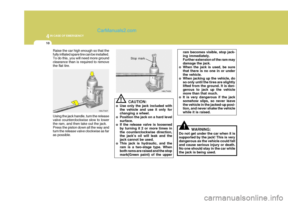
Raise the car high enough so that the fully inflated spare tire can be installed.To do this, you will need more ground clearance than is required to remove the flat tire. Using the jack handle, turn the release valve counterclockwise slow to lower the ram, and then take out the jack.Press the piston down all the way and turn the release valve clockwise as far as possible. HAUT407
HAUT409
CAUTION:
o Use only the jack included with the vehicle and use it only for changing a wheel.
o Position the jack on a hard level
surface.
o If the release valve is loosened
by turning it 2 or more times in the counterclockwise direction, the jack’s oil will leak and the jack cannot be used.
o This jack is hydraulic, and the ram is a two-stage type. Whenboth rams are raised and the stopmark(Green paint) of the upper
! Stop mark
ram becomes visible, stop jack- ing immediately.Further extension of the ram may damage the jack.
o When the jack is used, be sure
that there is no one in or underthe vehicle.
o When jacking up the vehicle, do so only until the tires are slightlylifted from the ground. It is dan- gerous to jack up the vehiclemore than that much.
o It is very dangerous if the jack
somehow slips, so never leavethe vehicle in the jacked-up posi- tion, and never shake the vehicle while it is raised.
WARNING:
Do not get under the car when it is supported by the jack! This is very dangerous as the vehicle could falland cause serious injury or death. No one should stay in the car while the jack is being used.
Page 113 of 205

44IN CASE OF EMERGENCY
12
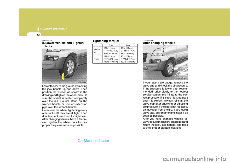
Tightening torque:
Minibus, Van Truck Front
12 to 14 kg.m (118 to 137 N.m, 87 to 101 lbs.ft) 18 to 22 kg.m(177 to 216 N.m, 130 to 159 lbs.ft)
Rear
12 to 14 kg.m (118 to 137 N.m, 87 to 101 lbs.ft) 18 to 22 kg.m(177 to 216 N.m, 130 to 159 lbs.ft)
E060J01A-AAT After changing wheels If you have a tire gauge, remove the valve cap and check the air pressure.If the pressure is lower than recom- mended, drive slowly to the nearest service station and inflate to the cor-rect pressure. If it is too high, adjust it until it is correct. Always reinstall the valve cap after checking or adjustingtire pressure. If the cap is not replaced, air may leak from the tire. If you lose a valve cap, buy another and install it assoon as possible. After you have changed wheels, al- ways secure the flat tire in its place andreturn the jack, jack handle, and tools to their proper storage locations. HSRFL065
D060I01P-GAT
8. Lower Vehicle and Tighten
Nuts
Lower the car to the ground by moving the jack handle up and down. Then position the wrench as shown in the drawing and tighten the wheel nuts. Besure the socket is seated completely over the nut. Do not stand on the wrench handle or use an extensionpipe over the wrench handle. Go around the wheel tightening every other nut until they are all tight. Thendouble-check each nut for tightness. After changing wheels, have a techni- cian tighten the wheel nuts to theirproper torque as soon as possible. HSRFL064
Page 130 of 205

4
CORROSION PREVENTION AND APPEARANCE CARE
29
4
IN CASE OF EMERGENCY
29
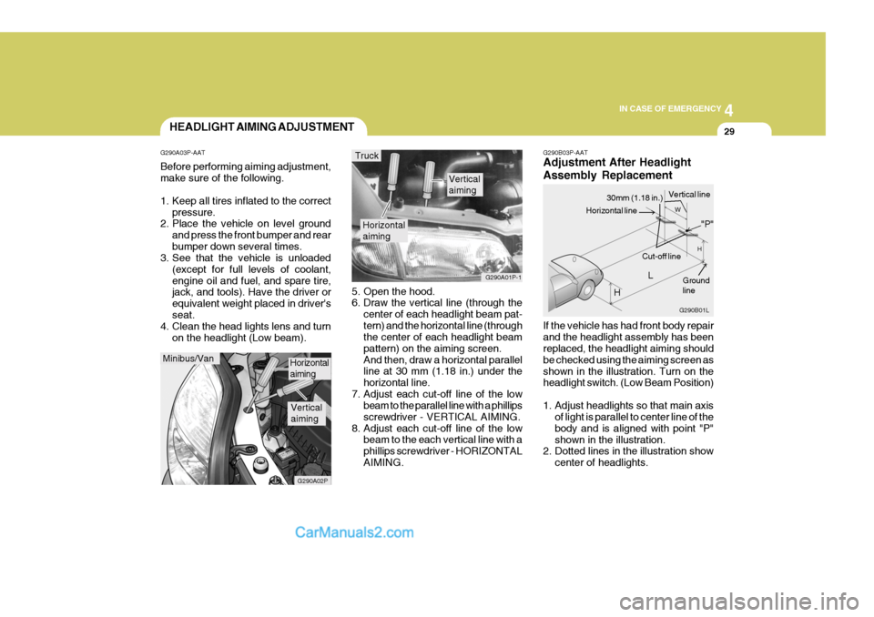
G290B03P-AAT Adjustment After Headlight Assembly Replacement If the vehicle has had front body repair and the headlight assembly has been replaced, the headlight aiming should be checked using the aiming screen asshown in the illustration. Turn on the headlight switch. (Low Beam Position)
1. Adjust headlights so that main axis
of light is parallel to center line of the body and is aligned with point "P"shown in the illustration.
2. Dotted lines in the illustration show
center of headlights.
5. Open the hood.
6. Draw the vertical line (through the
center of each headlight beam pat- tern) and the horizontal line (through the center of each headlight beam pattern) on the aiming screen.And then, draw a horizontal parallel line at 30 mm (1.18 in.) under the horizontal line.
7. Adjust each cut-off line of the low beam to the parallel line with a phillipsscrewdriver - VERTICAL AIMING.
8. Adjust each cut-off line of the low beam to the each vertical line with aphillips screwdriver - HORIZONTALAIMING.
Horizontal aiming
Verticalaiming
G290A01P-1
Truck
G290B01L
LW
H
H Cut-off line
Ground line
"P"
Horizontal line
30mm (1.18 in.) Vertical line
HEADLIGHT AIMING ADJUSTMENT
G290A03P-AAT Before performing aiming adjustment, make sure of the following.
1. Keep all tires inflated to the correct pressure.
2. Place the vehicle on level ground
and press the front bumper and rear bumper down several times.
3. See that the vehicle is unloaded
(except for full levels of coolant,engine oil and fuel, and spare tire, jack, and tools). Have the driver or equivalent weight placed in driver'sseat.
4. Clean the head lights lens and turn
on the headlight (Low beam).
Minibus/Van
G290A02P
Horizontal aiming
Verticalaiming
Page 203 of 205

10INDEX
4
I IF THE ENGINE OVERHEATS ................................ 4-25
IF THE ENGINE WILL NOT START .......................4-23
IF YOU HAVE A FLAT TIRE ..................................... 4-6
IGNITION SWITCH .................................................... 3-3
ILLUMINATED IGNITION SWITCH .........................1-11
IMMOBILIZER SYSTEM ............................................ 1-6
INCLI NOMETER ....................................................... 2-17
INSTALLATION OF ACCESSORIES ......................... 1-4
INSTRUMENT CLUSTER AND
INDICATOR LIGHTS ............................................... 2-2
INSTRUMENTS PANEL LIGHT CONTROL (RHEOSTAT) ......................................................... 2-24
INTERIOR LIGHT ..................................................... 2-28
J
JACK ........................................................................... 4-2JUMP STARTING ..................................................... 4-24
K
KEYS ........................................................................... 1-6 KEY POSITI ONS ........................................................ 3-3
L
LOADING .................................................................. 3-22
LOCKING DIFFERENTIAL ....... ................................3-31
LUBRICATION CHART .............................................. 9-4 MMAINTENANCE INTERVALS
..................................... 6-2
MAKING A FLAT SEAT .... .......................................1-36
MANUAL TRANSMISSION .................. ...................... 3-7
MEASUREMENT ........................................................ 9-2MULTI-FUNCTION LIGHT SWITCH Daytime Running Lights .................... ..................... 2-20
Headlight Flasher ................................................... 2-20
Headlight Switch .................................................... 2-19
High-beam Switch .................................................. 2-20
Lane Change Si gnal .............................................. 2-19
Parking Light Auto Cut .................. ........................ 2-20
Turn Signal Switch................................................. 2-19
MULTIMETER Altimeter ................................................................. 2-18
Inclinometer ............................................................ 2-17
Thermometer .......................................................... 2-17
OODOMETER/TRIP ODOMETER ..............................2-14
OPERATING THE SUNROOF SYSTEM .................2-31
OUTSIDE REARVIEW MIRROR ..............................2-34
OUTSIDE REARVIEW MIRROR HEATER ..............2-35
OVERDRIVE SWITCH ............................................. 3-12
OVERHEAD AIR COND ITIONING........................... 2-47