Page 243 of 289

Open the hood, and check the
physical condition of the battery.
In very cold weather, check the
condition of the electrolyte. If it
seems slushy or f rozen, do not try
jump starting until it thaws.
To jump start your vehicle:
You cannot start your vehicle by
pushing or pulling it. The numbers in the illustration show
the order to connect the jumper
cable.
1.
CONT INUED
Jump St art ing
T aking Care of t he Unexpect ed
253
BOOSTER
BATTERY
4-cylinder models
A battery can explode if you do
not follow the correct procedure,
seriously injuring anyonenearby.
Keep all sparks, open flames,
and smoking materials away
from the battery. If a battery sits in extreme
cold, the electrolyte inside can f reeze.
Attempting to jump start with a f rozen
battery can cause it to rupture.
�����—�����—�����y�
�����������
�y���
�(�����������y���������y
Although this seems like a simple
procedure, you should take several
precautions.
2.Turn of f all the electrical acces-
sories: heater, A/C, climate
control, stereo system, lights, etc.
Put the transmission in Neutral
(M/T) or Park (A/T), and set the
parking brake.
Page 244 of 289
�µ
�´
�´
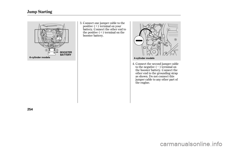
Connect the second jumper cable
to the negative ( ) terminal on
the booster battery. Connect the
other end to the grounding strap
as shown. Do not connect this
jumper cable to any other part of
the engine.
Connect one jumper cable to the
positive ( ) terminal on your
battery. Connect the other end to
the positive ( ) terminal on the
booster battery.
4.
3.
Jump Starting
254
4-cylinder models
BOOSTER
BATTERY
6-cylinder models
�����—�����—�����y�
�������������y���
�(�����������y���������y
Page 245 of 289
If the booster battery is in another
vehicle, have an assistant start
that vehicle and run it at a fast idle.
Start the vehicle. If the starter
motor still operates slowly, check
that the jumper cables have good
metal-to-metal contact.Once your vehicle is running,
disconnect the negative cable f rom
your vehicle, then f rom the
booster battery. Disconnect the
positive cable f rom your vehicle,
then from the booster battery.
Keep the ends of the jumper
cables away from each other and
any metal on the vehicle until
everything is disconnected.
Otherwise, you may cause an
electrical short.
7.
6.
5.
Jump Starting
T aking Care of t he Unexpect ed
255
6-cylinder models
�����—�����—�����y�
�������������y���
�(�����������y���������y
Page 249 of 289
Immediately turn of f all electrical
accessories. Try not to use other
electrically operated controls such as
the power windows. Keep the engine
running; starting the engine will
discharge the battery rapidly.
Go to a service station or garage
where you can get technical
assistance.
If the charging system indicator
comes on brightly when the engine
is running, the battery is not being
charged. If the indicator comes on while
driving, it means one of the engine’s
emission control systems may have a
problem. Even though you may f eel
no dif f erence in your vehicle’s
perf ormance, continued operation
may cause serious damage.
CONT INUED
Malf unction Indicator L amp
Charging System Indicator
Charging System Indicator, Malf unction Indicator L amp
T aking Care of t he Unexpect ed
259
CHARGING SYSTEM INDICATOR MALFUNCTION INDICATOR LAMP
�����—�����—�����y�
���������
���y���
�(�����������y���������y
Page 250 of 289

If the indicator remains on or the
f uel cap was not loose or missing,
have the vehicle checked by the
dealer as soon as possible.If your vehicle’s battery has been
disconnected or gone dead, these
codes are erased. It takes at least
three days of driving under various
conditions to set the codes again.
If you have recently ref ueled your
vehicle, the cause of this indicator
coming on could be a loose or
missing f uel f ill cap. Check the cap
or replace it. Tightening the cap will
not make the indicator turn of f
immediately; it takes at least three
days of normal driving.
Your vehicle has certain ‘‘readiness
codes’’ that are part of the on-board
diagnostics f or the emissions
systems. In some states, part of the
emissions testing is to make sure
these codes are set. If they are not
set, the test cannot be completed.To check if they are set, turn the
ignition to ON (II), without starting
the engine. The Malf unction
Indicator Lamp will come on f or 20
seconds. If it then goes of f , the
readiness codes are set. If it blinks 5
times, the readiness codes are not
set. If possible, do not take your
vehicle f or a state emissions test
until the readiness codes are set.
Refer to State Emissions Testing for
more inf ormation (see page ).
285
Readiness Codes
Malf unct ion Indicat or L amp
260
If you keep driving with the
Malf unction Indicator Lamp on, you
can damage your vehicle’s emissions
controls and engine. Those repairs may
not be covered by your vehicle’s
warranties. This indicator may also
come on with the ‘‘D’’ indicator.
�����—�����—���
�y�
����
��������y���
�(�����������y���������y
Page 254 of 289
, and keep the
speedbelow35mph(55km/h).If you decide to tow your vehicle
with all f our wheels on t")
With the f ront wheels on the ground,
it is best to tow the vehicle no farther
than 50 miles (80 km), and keep the
speedbelow35mph(55km/h).If you decide to tow your vehicle
with all f our wheels on the ground,
make sure you use a properly-
designed and attached tow bar.
Prepare the vehicle for towing as
described above, and leave the
ignition switch in Accessory (I) so
the steering wheel does not lock.
Make sure the radio and any items
plugged into the accessory power
socket are turned of f so they do not
rundownthebattery.
If your vehicle is equipped with a
f ront spoiler, remove it bef ore
towing so it is not damaged.
Emergency T owing
264
The steering system can be damaged if
the steering wheel is locked. Leave the
ignition switch in ACCESSORY (I), and
make sure the steering wheel turns
f reely bef ore you begin towing.
Trying to lif t or tow your vehicle by the
bumpers will cause serious damage.
The bumpers are not designed to
support the vehicle’s weight.
�����—�����—�����y�
�������������y���
�(�����������y���������y
Page 258 of 289
�µ�µ
�Î �Î �Î
�´
�Î
No. Amps. Circuits Protected No. Amps. Circuits Protected No. Amps. Circuits Protected
: 6-cylinder models
1 2345 10 A
(30A) 10 A
15 A
10 A Left Headlight Low
(Rear Defroster Coil)
Lef t Headlight Hi
Small Light
Right Headlight Hi 6789
10 10 A
7.5 A 15 A
20 A Right Headlight Low
Back Up
FI ECU
Condenser f an
Not Used 111112131415161717181819202122 23
20 A
30 A
7.5 A
20 A
40 A
40 A
15 A
30 A
30 A
20 A
40 A
40 A
(40 A) 40 A
100 A
50 A
50 A Cooling Fan
Cooling Fan
MG. Clutch
Horn, Stop
Rear Defroster
Back Up, ACC
Hazard
ABS Motor
TCS Motor
ABS F/S
TCS
Ignition Coil, DRL (Canada)
Power Seats, Seat Heaters
Heater Motor
Battery
Not Used
BIG1Main
Power Window Main
Fuses
268
UNDER-HOOD FUSE/RELAY BOX
�����—�����—�����y�
�����������
�y���
�(�����������y�������
�y
Page 264 of 289

�µ
�µ �µ�µ �µ �µ�µ�µ�µ�µ�µ�µ�µ�µ�µ�µ �µ �µ
�Î�Î
�Î�Î�Î
�Î�Î �Î�Î�Î
�Î
�Î�Î
�Î�Î �Î�Î
�Î�Î �Î�Î
CONT INUED
Specif ications
T echnical Inf ormation
275
Lights
Fuses
Battery Engine
Alignment
3.43 x 3.9 in (87.0 x 99.0 mm)
143.6 cu-in (2,354 cm
)
12 V 60 W (HB3)
12 V 51 W (HB4)
12 V 24/2.2 CP
9.7 : 1
3.39 x 3.39 in (86.0 x 86.0 mm)
182.8 cu-in (2,997 cm)
10 : 1
12 V
12 V
12 V
12 V
12 V
12 V
12 V 21 W
21/5 W
2CP
21 W
21 W
3CP8W
52 AH/5 HR
38 AH/5 HR
12 V
12 V
12 V
12 V
12 V
1.1 W
2CP
5W
8W8W
12 V
12 V
Headlights
Front turn signal/
Front parking lights
Rear turn signal lights
Stop/Taillights
Taillights
High-mount brake light
Back-up lights
License plate light
Ceiling light
Spotlights
Spotlights/Front ceiling lights
Trunk light
Door courtesy light
Vanity mirror lights
Interior
Under-hood
Capacity Type
BorexStroke
Displacement
Compression ratio
Spark plugs
Water cooled 4-stroke, DOHC
i-VTEC 4-cylinder, SOHC VTEC
6-cylinder (V6), gasoline engine
Toe-in
Camber
Caster 3°15’1°
0°
0.08 in (2.0 mm)
0.00 in (0.0 mm) IZFR6K-13 SKJ20DR-M13
SKJ20DR-M11
IZFR6K-11
See page 269 or the fuse label
attached to the inside of the fuse
box door on each side of the
dashboard.
See page 268 or the fuse box
cover. FrontRear
FrontRear
Front
HighLow
4-cylinder
6-cylinder
1: LX
2: EX (Amber)
3 : 4-cylinder models
4 : 6-cylinder models
5 : On some models NGK:
DENSO:NGK:
DENSO:
12
343
4
34
3, 4 3, 4
3, 5 3, 5
�����—�����—�����y�
�������������y���
�(�����������y���������y