2005 FORD F250 SUPER DUTY high beam
[x] Cancel search: high beamPage 15 of 312

Four wheel drive low: Illuminates
when four-wheel drive low is
engaged.
Four wheel drive indicator:
Illuminates when four-wheel drive is
engaged.
Speed control: Illuminates when
the speed control is activated. Turns
off when the speed control system
is deactivated.
Turn signal: Illuminates when the
left or right turn signal or the
hazard lights are turned on. If the
indicators stay on or flash faster, check for a burned out bulb.
High beams: Illuminates when the
high beam headlamps are turned on.
Key-in-ignition warning chime: Sounds when the key is left in the
ignition in the OFF, LOCK or ACCESSORY position and the driver’s door
is opened.
Headlamps on warning chime: Sounds when the headlamps or parking
lamps are on, the ignition is off (the key is not in the ignition) and the
driver’s door is opened.
Parking brake ON warning chime: Sounds when the parking brake is
set, the engine is running and the vehicle is driven more than 3 mph
(5 km). LOW
RANGE
4x4
2005 F250/350/450/550 (f23)
Owners Guide (post-2002-fmt)
USA_English (fus) Instrument Cluster
15
Page 40 of 312
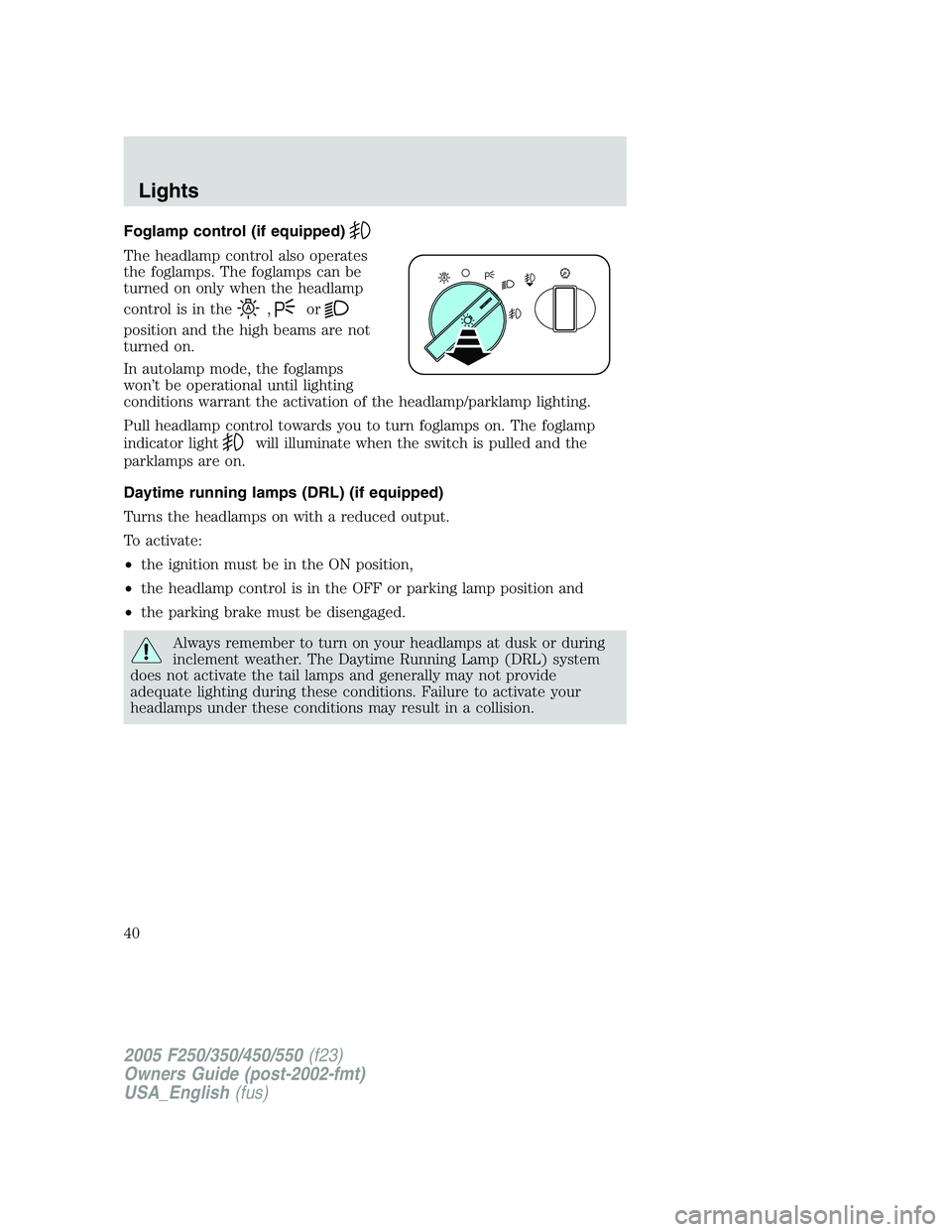
Foglamp control (if equipped)
The headlamp control also operates
the foglamps. The foglamps can be
turned on only when the headlamp
control is in the , or
position and the high beams are not
turned on.
In autolamp mode, the foglamps
won’t be operational until lighting
conditions warrant the activation of the headlamp/parklamp lighting.
Pull headlamp control towards you to turn foglamps on. The foglamp
indicator light will illuminate when the switch is pulled and the
parklamps are on.
Daytime running lamps (DRL) (if equipped)
Turns the headlamps on with a reduced output.
To activate:
• the ignition must be in the ON position,
• the headlamp control is in the OFF or parking lamp position and
• the parking brake must be disengaged.
Always remember to turn on your headlamps at dusk or during
inclement weather. The Daytime Running Lamp (DRL) system
does not activate the tail lamps and generally may not provide
adequate lighting during these conditions. Failure to activate your
headlamps under these conditions may result in a collision.
2005 F250/350/450/550 (f23)
Owners Guide (post-2002-fmt)
USA_English (fus)Lights
40
Page 41 of 312
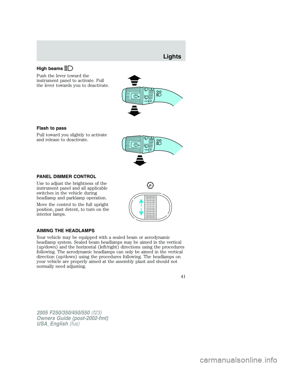
High beams
Push the lever toward the
instrument panel to activate. Pull
the lever towards you to deactivate.
Flash to pass
Pull toward you slightly to activate
and release to deactivate.
PANEL DIMMER CONTROL
Use to adjust the brightness of the
instrument panel and all applicable
switches in the vehicle during
headlamp and parklamp operation.
Move the control to the full upright
position, past detent, to turn on the
interior lamps.
AIMING THE HEADLAMPS
Your vehicle may be equipped with a sealed beam or aerodynamic
headlamp system. Sealed beam headlamps may be aimed in the vertical
(up/down) and the horizontal (left/right) directions using the procedures
following. The aerodynamic headlamps can only be aimed in the vertical
direction (up/down) using the procedures following. The headlamps on
your vehicle are properly aimed at the assembly plant and should not
normally need adjusting.
2005 F250/350/450/550 (f23)
Owners Guide (post-2002-fmt)
USA_English (fus) Lights
41
Page 42 of 312
Vertical and horizontal aim adjustment (sealed beam headlamps)
The headlamps on your vehicle are intended to be aimed using
mechanical aimers. If mechanical aimers are used and the cross-car sight
line is in any way blocked, set the legs of the universal adaptor all to the
same setting, such that the cross-car sight line is no longer blocked, per
the instructions for the brand of mechanical aimer used. You can also
aim the headlamps visually using the procedure below.
To adjust the headlamps:
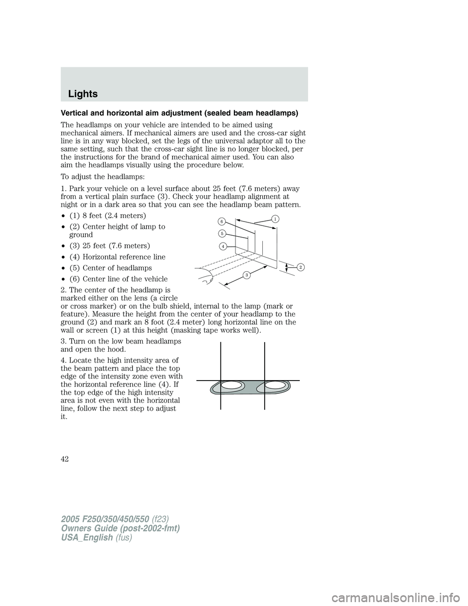
1. Park your vehicle on a level surface about 25 feet (7.6 meters) away
from a vertical plain surface (3). Check your headlamp alignment at
night or in a dark area so that you can see the headlamp beam pattern.
• (1) 8 feet (2.4 meters)
• (2) Center height of lamp to
ground
• (3) 25 feet (7.6 meters)
• (4) Horizontal reference line
• (5) Center of headlamps
• (6) Center line of the vehicle
2. The center of the headlamp is
marked either on the lens (a circle
or cross marker) or on the bulb shield, internal to the lamp (mark or
feature). Measure the height from the center of your headlamp to the
ground (2) and mark an 8 foot (2.4 meter) long horizontal line on the
wall or screen (1) at this height (masking tape works well).
3. Turn on the low beam headlamps
and open the hood.
4. Locate the high intensity area of
the beam pattern and place the top
edge of the intensity zone even with
the horizontal reference line (4). If
the top edge of the high intensity
area is not even with the horizontal
line, follow the next step to adjust
it.
2005 F250/350/450/550 (f23)
Owners Guide (post-2002-fmt)
USA_English (fus)Lights
42
Page 43 of 312
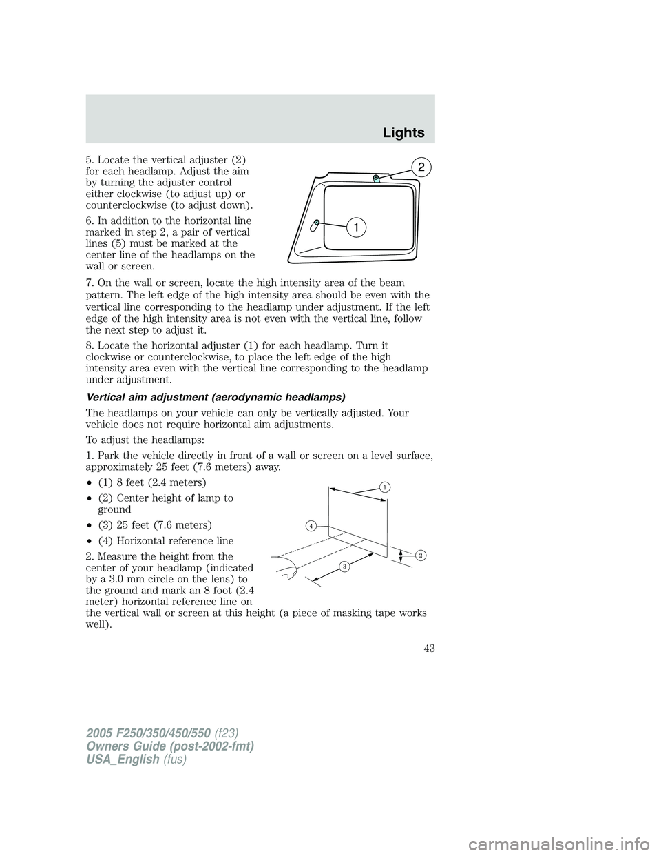
5. Locate the vertical adjuster (2)
for each headlamp. Adjust the aim
by turning the adjuster control
either clockwise (to adjust up) or
counterclockwise (to adjust down).
6. In addition to the horizontal line
marked in step 2, a pair of vertical
lines (5) must be marked at the
center line of the headlamps on the
wall or screen.
7. On the wall or screen, locate the high intensity area of the beam
pattern. The left edge of the high intensity area should be even with the
vertical line corresponding to the headlamp under adjustment. If the left
edge of the high intensity area is not even with the vertical line, follow
the next step to adjust it.
8. Locate the horizontal adjuster (1) for each headlamp. Turn it
clockwise or counterclockwise, to place the left edge of the high
intensity area even with the vertical line corresponding to the headlamp
under adjustment.
Vertical aim adjustment (aerodynamic headlamps)
The headlamps on your vehicle can only be vertically adjusted. Your
vehicle does not require horizontal aim adjustments.
To adjust the headlamps:
1. Park the vehicle directly in front of a wall or screen on a level surface,
approximately 25 feet (7.6 meters) away.
• (1) 8 feet (2.4 meters)
• (2) Center height of lamp to
ground
• (3) 25 feet (7.6 meters)
• (4) Horizontal reference line
2. Measure the height from the
center of your headlamp (indicated
by a 3.0 mm circle on the lens) to
the ground and mark an 8 foot (2.4
meter) horizontal reference line on
the vertical wall or screen at this height (a piece of masking tape works
well).
2005 F250/350/450/550 (f23)
Owners Guide (post-2002-fmt)
USA_English (fus) Lights
43
Page 46 of 312

Replacing exterior bulbs
Check the operation of all the bulbs frequently.
Function Number of
bulbs Trade number
Headlamps (aerodynamic) 2 H13/9008
Headlamps (sealed beam) 2 H6054
Park lamp with aerodynamic
headlamp 2 3157AK or 3157A
Park lamp with sealed beam
headlamp 2 4157K/3157
Sidemarker 2 194
Tail/stop/turn/sidemarker 2 4157K/3157
Backup 2 3156K or 3156
High-mount stoplamp 1 922
Foglamp 2 9145
License plate lamp 2 194
Cargo lamp 2 906
Roofmarker 5 194
Rear fender clearance* 4 W5W
Interior visor lamp (if
equipped) 4 194
Rear identification 3 194
All replacement bulbs are clear in color except where noted.
To replace all instrument panel lights - see your dealer
* Dual rear wheels, or if equipped.
Replacing headlamp bulbs (aerodynamic)
1. Make sure that the headlamp control is in the OFF position and open
the hood.
2005 F250/350/450/550 (f23)
Owners Guide (post-2002-fmt)
USA_English (fus)Lights
46
Page 109 of 312
Do not attempt to service, repair, or modify the air bag
supplemental restraint systems or its fuses. See your Ford or
Lincoln/Mercury dealer.
The front passenger air bag is not designed to offer protection to
an occupant in the center front seating position.
Modifying or adding equipment to the front end of the vehicle
(including frame, bumper, front end body structure and tow
hooks) may affect the performance of the air bag system, increasing
the risk of injury. Do not modify the front end of the vehicle.
Additional equipment such as snowplow equipment may effect
the performance of the air bag sensors increasing the risk of
injury. Please refer to the Body Builders Layout Book for instructions
about the appropriate installation of additional equipment.
Removing the blocker beam without installing snow plow
attachment hardware may effect air bag deployment in a crash.
Do not operate the truck unless either the blocker beam or snow plow
attachment hardware is installed on the vehicle.
Children and air bags
For additional important safety information, read all information on
safety restraints in this guide.
Children must always be properly restrained. Failure to follow these
instructions may increase the risk of injury in a collision.
An infant in a rear-facing seat faces a high risk of serious or fatal
injuries from a deploying passenger air bag. Rear facing infant
seats should NEVER be placed in the front seats, unless the passenger
air bag is turned off. See Passenger air bag ON/OFF switch.
2005 F250/350/450/550 (f23)
Owners Guide (post-2002-fmt)
USA_English (fus) Seating and Safety Restraints
109
Page 212 of 312
Do not attempt to service, repair, or modify the air bag
supplemental restraint system (SRS) or its fuses. See your Ford
or Lincoln Mercury dealer.
Additional equipment such as snowplow equipment may effect
the performance of the air bag sensors increasing the risk of
injury. Please refer to the Body Builders Layout Book for instructions
about the appropriate installation of additional equipment.
Transmission operation while plowing
• Shift transfer case to 4x4 LOW (4WD Low) when plowing in small
areas at speeds below 5 mph (8 km/h).
• Shift transfer case to 4x4 HIGH (4WD High) when plowing larger areas
or light snow at higher speeds. Do not exceed 15 mph (24 km/h).
• Do not shift the transmission from a forward gear to R (Reverse) until
the engine is at idle and the wheels are stopped.
• If the vehicle is stuck, shift the transmission in a steady motion
between forward and reverse gears. Do not rock the vehicle for more
than a few minutes. The transmission and tires may be damaged or
the engine can overheat.
Do not rock the vehicle if the engine is not at normal operating
temperature. Do not rock the vehicle for more than a minute. The
transmission and tires may be damaged or the engine may overheat.
Refer to Transmission temperature gauge in the Instrument Cluster
chapter for transmission fluid temperature information.
Do not spin the wheels at over 35 mph (55 km/h). The tires may
fail and injure a passenger or bystander.
Removing the snowplow frame mount
A metal crossmember is included below the front bumper on Super Duty
vehicles called a “BlockerBeam”. Typical snowplow installations require
removal of this BlockerBeam to install the snowplow mounting hardware
to the vehicle frame.
The BlockerBeam must be re-installed if the snowplow
frame-mounting hardware is removed from the vehicle to assure
proper air bag deployment in a crash.
2005 F250/350/450/550 (f23)
Owners Guide (post-2002-fmt)
USA_English (fus)Driving
212