Page 64 of 368

5. Use the cursor control to increase
or decrease the levels. The higher
the level selected, the greater the
compensation. The levels will be
shown in the display. Decrease all
the way to the left to turn AVC off.
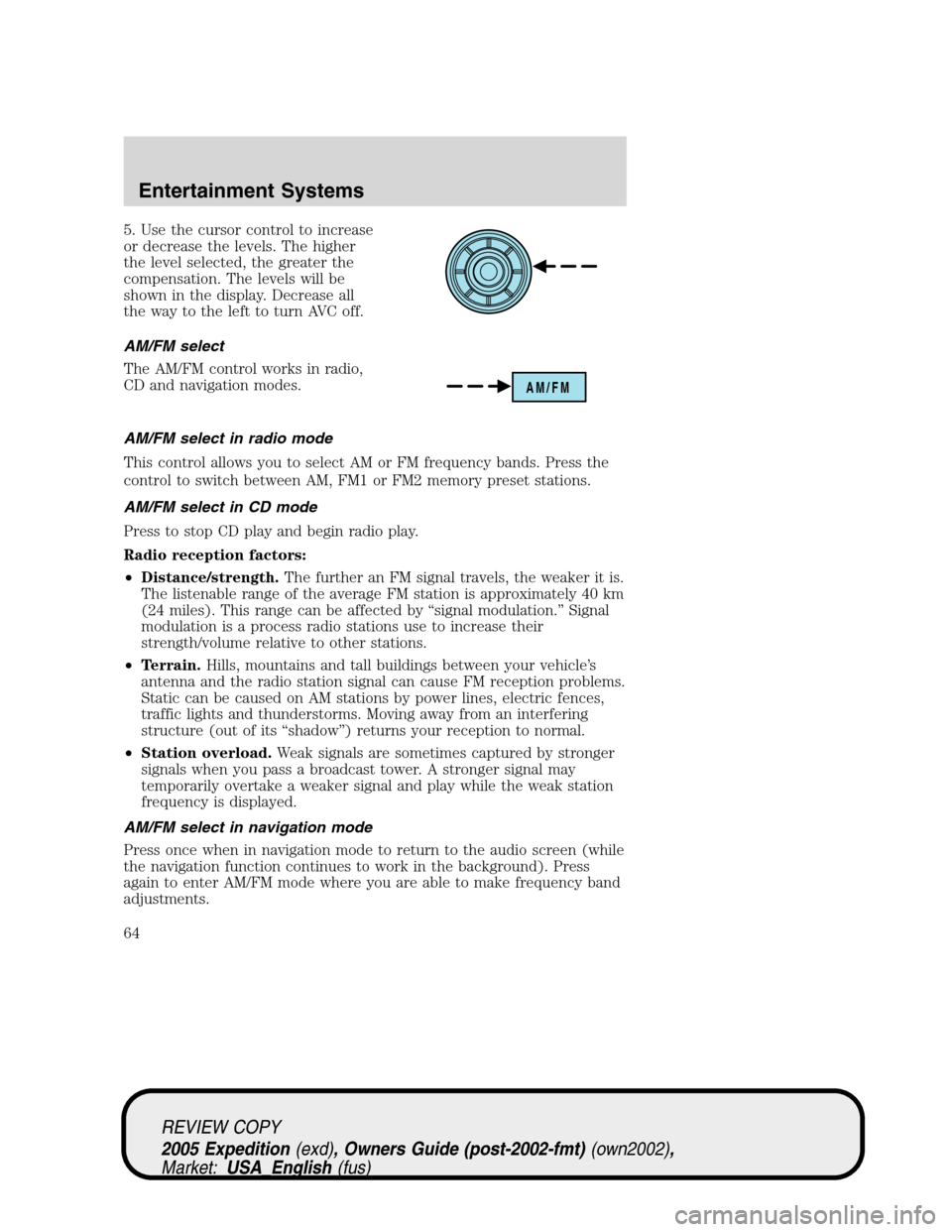
AM/FM select
The AM/FM control works in radio,
CD and navigation modes.
AM/FM select in radio mode
This control allows you to select AM or FM frequency bands. Press the
control to switch between AM, FM1 or FM2 memory preset stations.
AM/FM select in CD mode
Press to stop CD play and begin radio play.
Radio reception factors:
•Distance/strength.The further an FM signal travels, the weaker it is.
The listenable range of the average FM station is approximately 40 km
(24 miles). This range can be affected by “signal modulation.” Signal
modulation is a process radio stations use to increase their
strength/volume relative to other stations.
•Terrain.Hills, mountains and tall buildings between your vehicle’s
antenna and the radio station signal can cause FM reception problems.
Static can be caused on AM stations by power lines, electric fences,
traffic lights and thunderstorms. Moving away from an interfering
structure (out of its “shadow”) returns your reception to normal.
•Station overload.Weak signals are sometimes captured by stronger
signals when you pass a broadcast tower. A stronger signal may
temporarily overtake a weaker signal and play while the weak station
frequency is displayed.
AM/FM select in navigation mode
Press once when in navigation mode to return to the audio screen (while
the navigation function continues to work in the background). Press
again to enter AM/FM mode where you are able to make frequency band
adjustments.
AM/FM
REVIEW COPY
2005 Expedition(exd), Owners Guide (post-2002-fmt)(own2002),
Market:USA_English(fus)
Entertainment Systems
64
Page 294 of 368

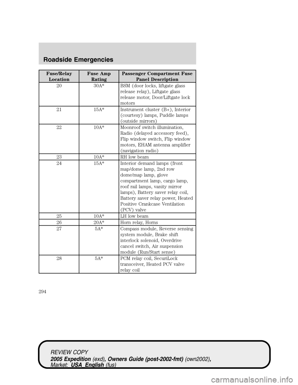
Fuse/Relay
LocationFuse Amp
RatingPassenger Compartment Fuse
Panel Description
20 30A* BSM (door locks, liftgate glass
release relay), Liftgate glass
release motor, Door/Liftgate lock
motors
21 15A* Instrument cluster (B+), Interior
(courtesy) lamps, Puddle lamps
(outside mirrors)
22 10A* Moonroof switch illumination,
Radio (delayed accessory feed),
Flip window switch, Flip window
motors, EHAM antenna amplifier
(navigation radio)
23 10A* RH low beam
24 15A* Interior demand lamps (front
map/dome lamp, 2nd row
dome/map lamp, glove
compartment lamp, cargo lamp,
roof rail lamps, vanity mirror
lamps), Battery saver relay coil,
Battery saver relay power, Heated
Positive Crankcase Ventilation
(PCV) valve
25 10A* LH low beam
26 20A* Horn relay, Horns
27 5A* Compass module, Reverse sensing
system module, Brake shift
interlock solenoid, Overdrive
cancel switch, Air suspension
module (Run/Start sense)
28 5A* PCM relay coil, SecuriLock
transceiver, Heated PCV valve
relay coil
REVIEW COPY
2005 Expedition(exd), Owners Guide (post-2002-fmt)(own2002),
Market:USA_English(fus)
Roadside Emergencies
294
Page 297 of 368

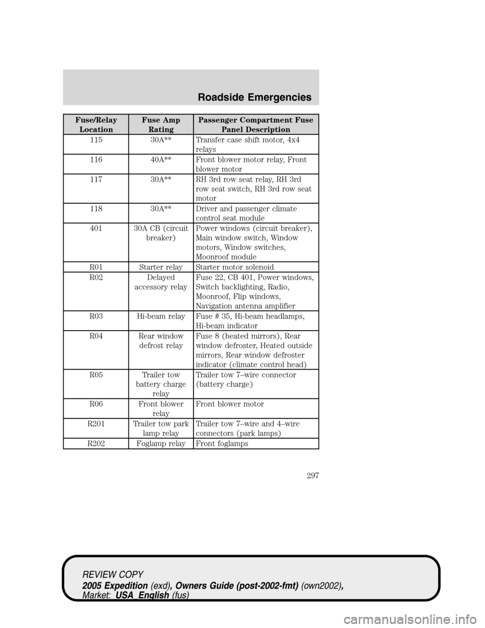
Fuse/Relay
LocationFuse Amp
RatingPassenger Compartment Fuse
Panel Description
115 30A** Transfer case shift motor, 4x4
relays
116 40A** Front blower motor relay, Front
blower motor
117 30A** RH 3rd row seat relay, RH 3rd
row seat switch, RH 3rd row seat
motor
118 30A** Driver and passenger climate
control seat module
401 30A CB (circuit
breaker)Power windows (circuit breaker),
Main window switch, Window
motors, Window switches,
Moonroof module
R01 Starter relay Starter motor solenoid
R02 Delayed
accessory relayFuse 22, CB 401, Power windows,
Switch backlighting, Radio,
Moonroof, Flip windows,
Navigation antenna amplifier
R03 Hi-beam relay Fuse # 35, Hi-beam headlamps,
Hi-beam indicator
R04 Rear window
defrost relayFuse 8 (heated mirrors), Rear
window defroster, Heated outside
mirrors, Rear window defroster
indicator (climate control head)
R05 Trailer tow
battery charge
relayTrailer tow 7–wire connector
(battery charge)
R06 Front blower
relayFront blower motor
R201 Trailer tow park
lamp relayTrailer tow 7–wire and 4–wire
connectors (park lamps)
R202 Foglamp relay Front foglamps
REVIEW COPY
2005 Expedition(exd), Owners Guide (post-2002-fmt)(own2002),
Market:USA_English(fus)
Roadside Emergencies
297
Page 361 of 368
•To avoid interference with other vehicle functions, such as anti-lock
braking systems, amateur radio users who install radios and antennas
onto their vehicle should not locate the Amateur Radio Antennas in
the area of the driver’s side hood.
•Electrical or electronic accessories or components that are
non-Genuine Ford Accessories added to the vehicle by the dealer or
the owner may adversely affect battery performance and durability.
REVIEW COPY
2005 Expedition(exd), Owners Guide (post-2002-fmt)(own2002),
Market:USA_English(fus)
Accessories
361