Page 110 of 368

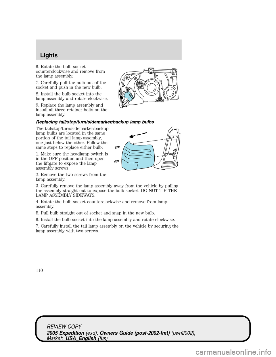
6. Rotate the bulb socket
counterclockwise and remove from
the lamp assembly.
7. Carefully pull the bulb out of the
socket and push in the new bulb.
8. Install the bulb socket into the
lamp assembly and rotate clockwise.
9. Replace the lamp assembly and
install all three retainer bolts on the
lamp assembly.
Replacing tail/stop/turn/sidemarker/backup lamp bulbs
The tail/stop/turn/sidemarker/backup
lamp bulbs are located in the same
portion of the tail lamp assembly,
one just below the other. Follow the
same steps to replace either bulb:
1. Make sure the headlamp switch is
in the OFF position and then open
the liftgate to expose the lamp
assembly screws.
2. Remove the two screws from the
lamp assembly.
3. Carefully remove the lamp assembly away from the vehicle by pulling
the assembly straight out to expose the bulb socket. DO NOT TIP THE
LAMP ASSEMBLY SIDEWAYS.
4. Rotate the bulb socket counterclockwise and remove from lamp
assembly.
5. Pull bulb straight out of socket and snap in the new bulb.
6. Install the bulb socket into the lamp assembly and rotate clockwise.
7. Carefully install the tail lamp assembly on the vehicle by securing the
lamp assembly with two screws.
REVIEW COPY
2005 Expedition(exd), Owners Guide (post-2002-fmt)(own2002),
Market:USA_English(fus)
Lights
110
Page 111 of 368

Replacing foglamp bulbs
Handle a halogen headlamp bulb carefully and keep out of
children’s reach. Grasp the bulb only by its plastic base and do
not touch the glass. The oil from your hand could cause the bulb to
break the next time the headlamps are operated.
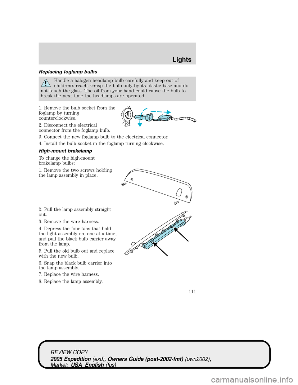
1. Remove the bulb socket from the
foglamp by turning
counterclockwise.
2. Disconnect the electrical
connector from the foglamp bulb.
3. Connect the new foglamp bulb to the electrical connector.
4. Install the bulb socket in the foglamp turning clockwise.
High-mount brakelamp
To change the high-mount
brakelamp bulbs:
1. Remove the two screws holding
the lamp assembly in place.
2. Pull the lamp assembly straight
out.
3. Remove the wire harness.
4. Depress the four tabs that hold
the light assembly on, one at a time,
and pull the black bulb carrier away
from the lamp.
5. Pull the old bulb out and replace
with the new bulb.
6. Snap the black bulb carrier into
the lamp assembly.
7. Replace the wire harness.
8. Replace the lamp assembly.
REVIEW COPY
2005 Expedition(exd), Owners Guide (post-2002-fmt)(own2002),
Market:USA_English(fus)
Lights
111
Page 112 of 368

Replacing license plate lamp bulb
The license plate bulbs are located in the license plate housing assembly
on the liftgate. To change the license plate bulbs:
1. Make sure the headlamp switch is
in the OFF position.
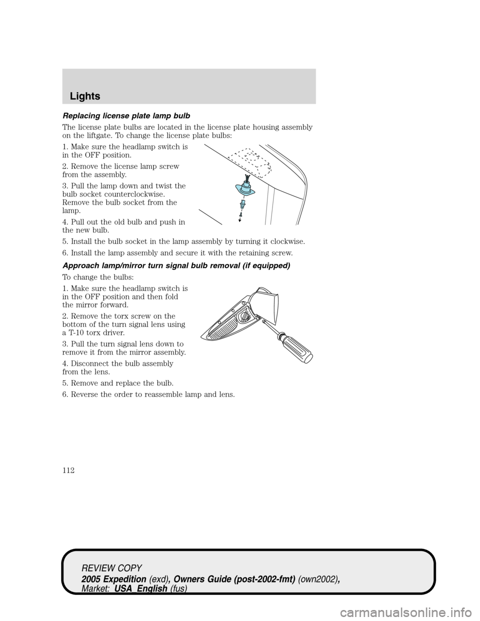
2. Remove the license lamp screw
from the assembly.
3. Pull the lamp down and twist the
bulb socket counterclockwise.
Remove the bulb socket from the
lamp.
4. Pull out the old bulb and push in
the new bulb.
5. Install the bulb socket in the lamp assembly by turning it clockwise.
6. Install the lamp assembly and secure it with the retaining screw.
Approach lamp/mirror turn signal bulb removal (if equipped)
To change the bulbs:
1. Make sure the headlamp switch is
in the OFF position and then fold
the mirror forward.
2. Remove the torx screw on the
bottom of the turn signal lens using
a T-10 torx driver.
3. Pull the turn signal lens down to
remove it from the mirror assembly.
4. Disconnect the bulb assembly
from the lens.
5. Remove and replace the bulb.
6. Reverse the order to reassemble lamp and lens.
REVIEW COPY
2005 Expedition(exd), Owners Guide (post-2002-fmt)(own2002),
Market:USA_English(fus)
Lights
112
Page 113 of 368
Approach lamp bulb removal (if equipped)
To change the bulbs:
1. Make sure that all the doors are
closed and the interior lights have
automatically turned off or the
opposite mirror approach lamp has
turned off.
2. With a small flat tipped
screwdriver, insert the tip into the
approach light module slot located
on the outboard corner of the lens
to release the clip.
3. While holding the clip in the release position, pull the approach light
module down.
4. Remove the two wires from the module and replace the module with a
new one.
5. Reverse the order to reassemble the approach light module.
REVIEW COPY
2005 Expedition(exd), Owners Guide (post-2002-fmt)(own2002),
Market:USA_English(fus)
Lights
113
Page 117 of 368

Forward storage bin and conversation mirror (if equipped)
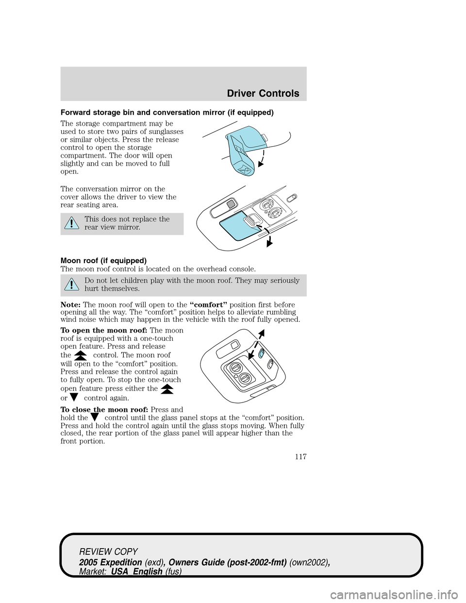
The storage compartment may be
used to store two pairs of sunglasses
or similar objects. Press the release
control to open the storage
compartment. The door will open
slightly and can be moved to full
open.
The conversation mirror on the
cover allows the driver to view the
rear seating area.
This does not replace the
rear view mirror.
Moon roof (if equipped)
The moon roof control is located on the overhead console.
Do not let children play with the moon roof. They may seriously
hurt themselves.
Note:The moon roof will open to the“comfort”position first before
opening all the way. The “comfort” position helps to alleviate rumbling
wind noise which may happen in the vehicle with the roof fully opened.
To open the moon roof:The moon
roof is equipped with a one-touch
open feature. Press and release
the
control. The moon roof
will open to the “comfort” position.
Press and release the control again
to fully open. To stop the one-touch
open feature press either the
orcontrol again.
To close the moon roof:Press and
hold the
control until the glass panel stops at the “comfort” position.
Press and hold the control again until the glass stops moving. When fully
closed, the rear portion of the glass panel will appear higher than the
front portion.
REVIEW COPY
2005 Expedition(exd), Owners Guide (post-2002-fmt)(own2002),
Market:USA_English(fus)
Driver Controls
117
Page 119 of 368
Do not plug optional electrical
accessories into the cigarette lighter.
Use the power point.
Do not use the power point for
operating the cigarette lighter
element.
The maximum power each power
point can supply depends on the
fuse rating. For example: a 20A fuse
should supply a maximum of 240
Watts, a 15A fuse should supply a maximum of 180 Watts and a 10A fuse
should supply a maximum of 120 Watts. Exceeding these limits will
result in a blown fuse.
Always keep the power point caps closed when not being used.
The third auxiliary power point on
the center console is accessible from
the rear seats.
The rear auxiliary power point is located on the right rear quarter panel.
The power point is accessible from the liftgate or the third row seat.
Equipped with rear climate
control
4 3 2 1 0
REVIEW COPY
2005 Expedition(exd), Owners Guide (post-2002-fmt)(own2002),
Market:USA_English(fus)
Driver Controls
119
Page 121 of 368

Window lock
The window lock feature allows only
the driver to operate the power
windows.
To lock out all the window controls
except for the driver’s press the left
side of the control. Press the right
side to restore the window controls.
Accessory delay
With accessory delay, the window switches, audio system and moon roof
may be used for up to ten minutes after the ignition switch is turned to
the OFF position or until any door is opened.
MIRRORS
Automatic dimming inside rear view mirror (if equipped)
Your vehicle may be equipped with
an inside rear view mirror with an
auto-dimming function. The
electronic day/night mirror will
change from the normal (high
reflective) state to the non-glare
(darkened) state when bright lights (glare) reach the mirror. When the
mirror detects bright light from behind the vehicle, it will automatically
adjust (darken) to minimize glare.
The mirror will automatically return to the normal state whenever the
vehicle is placed in R (Reverse) to ensure a bright clear view when
backing up.
Do not block the sensor on the backside of the inside rear view mirror
since this may impair proper mirror performance.
Power side view mirrors
The ignition can be in any position to adjust the power side view mirrors.
To adjust your mirrors:
REVIEW COPY
2005 Expedition(exd), Owners Guide (post-2002-fmt)(own2002),
Market:USA_English(fus)
Driver Controls
121
Page 124 of 368
Setting speed control
The controls for using your speed
control are located on the steering
wheel for your convenience.
1. Press the ON control and release
it.
2. Accelerate to the desired speed.
3. Press the SET + control and
release it.
4. Take your foot off the accelerator
pedal.
5. The indicator light
on the
instrument cluster will turn on.
Note:
•Vehicle speed may vary momentarily when driving up and down a
steep hill.
•If the vehicle speed increases above the set speed on a downhill, you
may want to apply the brakes to reduce the speed.
•If the vehicle speed decreases more than 10 mph (16 km/h) below
your set speed on an uphill, your speed control will disengage.
RES
SET
COAST+
REVIEW COPY
2005 Expedition(exd), Owners Guide (post-2002-fmt)(own2002),
Market:USA_English(fus)
Driver Controls
124