Page 275 of 368

CONTROL TRAC FOUR-WHEEL DRIVE (4X4) OPERATION
(IF EQUIPPED)
For important information regarding safe operation of this type
of vehicle, seePreparing to drive your vehiclein this chapter.
If equipped with the Control Trac 4x4 System, and 4L (4x4 LOW)
is selected while the vehicle is moving, the system will not
engage. This is normal and should be no reason for concern.
Before 4L (4x4 LOW) can be engaged, the vehicle must be
brought to a complete stop, the brake pedal depressed and the
transmission placed in N (Neutral).
The vehicle should not be operated in 4H (4x4 HIGH) or 4L (4x4 LOW)
on dry pavement. Doing so could result in difficult disengagement of the
transfer case, increased tire wear, decreased fuel economy and may
damage driveline components.
Your 4x4 features the heavy-duty Control Trac system which includes a
computer-operated transfer case. This unique system is interactive with
the road, continually monitoring and adjusting torque delivery to the
front and rear wheels to optimize vehicle control.
System indicator lights
The Control Trac system indicator lights illuminate only under the
following conditions. If these lights illuminate when driving in 2H or
A4WD, contact your Ford dealer as soon as possible.
•4X4 HIGH- momentarily
illuminates when the vehicle is
started. Illuminates when 4H is
selected.
•4X4 LOW– momentarily
illuminates when the vehicle is
started. Illuminates when 4L is
selected.
4x4
HIGH
4x4
LOW
REVIEW COPY
2005 Expedition(exd), Owners Guide (post-2002-fmt)(own2002),
Market:USA_English(fus)
Driving
275
Page 286 of 368

GETTING ROADSIDE ASSISTANCE
To fully assist you should you have a vehicle concern, Ford Motor
Company offers a complimentary roadside assistance program. This
program is separate from the New Vehicle Limited Warranty. The service
is available:
•24–hours, seven days a week
•for the New Vehicle Limited Warranty period of three years or
36,000 miles (60,000 km), whichever occurs first on Ford and Mercury
vehicles, and four years or 50,000 miles (80,000 km) on Lincoln
vehicles.
Roadside assistance will cover:
•a flat tire change with a good spare (except Ford GT which has a tire
inflation kit)
•battery jump start
•lock-out assistance (key replacement cost is the customer’s
responsibility)
•fuel delivery (2.0 gallons [7.5L], maximum two occurrences within
12 month period)
•towing of your disabled vehicle to the nearest Ford Motor Company
dealership, or your selling dealer if within 35 miles (56.3 km) of the
nearest Ford Motor Company dealership (one tow per disablement).
Even non-warranty related tows, like accidents, are covered (some
exclusions apply, such as impound towing or repossession).
Canadian customers refer to your Owner Information Guide for
information on:
•coverage period
•exact fuel amounts
•towing of your disabled vehicle
•emergency travel expense reimbursement
•travel planning benefits
USING ROADSIDE ASSISTANCE
Complete the roadside assistance identification card and place it in your
wallet for quick reference. In the United States, this card is found in the
Owner Guide portfolio in the glove compartment. In Canada, the card is
found in theOwner Information Guidein the glove compartment.
U.S. Ford or Mercury vehicle customers who require roadside assistance,
call 1–800–241–3673; Lincoln vehicle customers call 1–800–521–4140.
REVIEW COPY
2005 Expedition(exd), Owners Guide (post-2002-fmt)(own2002),
Market:USA_English(fus)
Roadside Emergencies
Roadside Emergencies
286
Page 287 of 368

Canadian customers who require roadside assistance, call
1–800–665–2006.
If you need to arrange roadside assistance for yourself, Ford Motor
Company will reimburse a reasonable amount. To obtain reimbursement
information, U.S. Ford or Mercury vehicles customers call
1-800-241-3673; Lincoln vehicle customers call 1–800–521–4140.
Canadian customers who need to obtain reimbursement information, call
1–800–665–2006.
ROADSIDE COVERAGE BEYOND BASIC WARRANTY
In the United States, you may purchase additional roadside assistance
coverage beyond this period through the Ford Auto Club by contacting
your Ford or Lincoln Mercury dealer.
Similarly in Canada, for uninterrupted Roadside Assistance coverage, you
may purchase extended coverage prior to your Basic Warranty’s Roadside
Assistance expiring. For more information and enrollment, contact
1–877–294–2582 or visit our website at www.ford.ca.
HAZARD FLASHER
Use only in an emergency to warn traffic of vehicle breakdown,
approaching danger, etc. The hazard flashers can be operated when the
ignition is off.
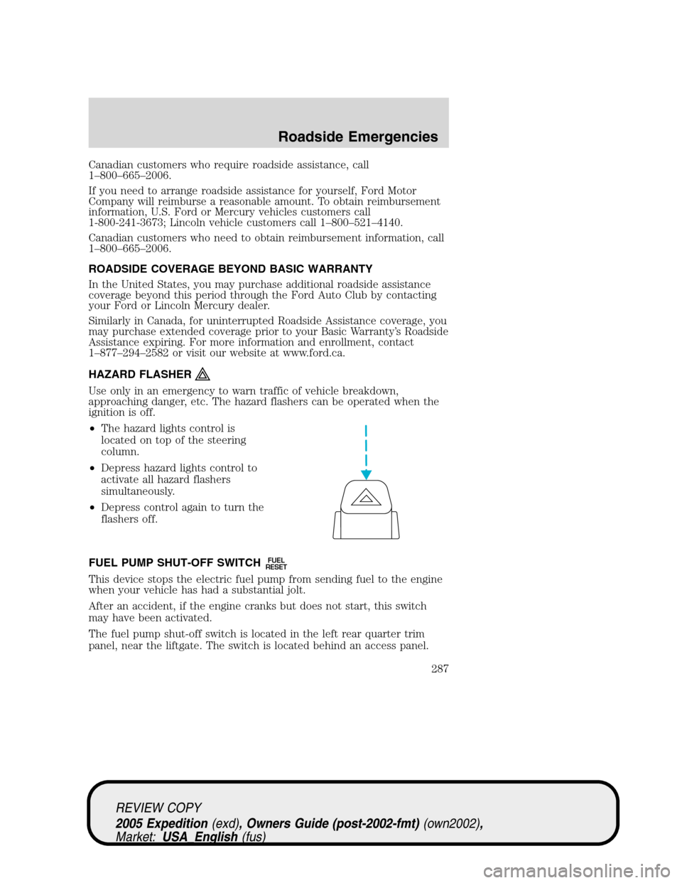
•The hazard lights control is
located on top of the steering
column.
•Depress hazard lights control to
activate all hazard flashers
simultaneously.
•Depress control again to turn the
flashers off.
FUEL PUMP SHUT-OFF SWITCH
FUEL
RESET
This device stops the electric fuel pump from sending fuel to the engine
when your vehicle has had a substantial jolt.
After an accident, if the engine cranks but does not start, this switch
may have been activated.
The fuel pump shut-off switch is located in the left rear quarter trim
panel, near the liftgate. The switch is located behind an access panel.
REVIEW COPY
2005 Expedition(exd), Owners Guide (post-2002-fmt)(own2002),
Market:USA_English(fus)
Roadside Emergencies
287
Page 288 of 368
The fuel pump shut-off switch has a
red reset button on top of it and is
located beneath the air suspension
switch (if equipped).
Use the following procedure to reset the fuel pump shut-off switch.
1. Turn the ignition to the OFF position.
2. Check the fuel system for leaks.
3. If no fuel leak is apparent, reset the fuel pump shut-off switch by
pushing in on the reset button.
4. Turn the ignition to the ON position. Pause for a few seconds and
return the key to the OFF position.
5. Make a further check for leaks in the fuel system.
FUSES AND RELAYS
Fuses
If electrical components in the
vehicle are not working, a fuse may
have blown. Blown fuses are
identified by a broken wire within
the fuse. Check the appropriate
fuses before replacing any electrical
components.
15
REVIEW COPY
2005 Expedition(exd), Owners Guide (post-2002-fmt)(own2002),
Market:USA_English(fus)
Roadside Emergencies
288
Page 293 of 368

Fuse/Relay
LocationFuse Amp
RatingPassenger Compartment Fuse
Panel Description
12 15A* Fuel pump relay, Fuel pump
shut-off switch, Fuel pump driver
module, Fuel pump motor
13 10A* Manual climate control mode
switch, Rear window defroster
relay coil, A/C refrigerant
containment switch, A/C de-icing
switch, A/C low pressure switch,
DEATC control head, DEATC
solenoids, DEATC blower control,
Trailer tow battery charge relay
coil
14 10A* Daytime Running Lamps (DRL)
ignition relay coil, Digital
Transmission Range Sensor
(DTRS) back-up lamps, Trailer
tow back-up lamps relay coil,
Electrochromatic mirror,
Navigation radio, Manual A/C
blend door actuator
15 5A* AdvanceTrac�with RSC switch,
Instrument cluster (Run/Start
feed)
16 10A* ABS/AdvanceTrac�with RSC
module (Run/Start feed)
17 15A* Foglamps
18 10A* Auxiliary A/C temperature blend
door actuator, Auxiliary A/C front
auxiliary control, Turn signal
flasher, Electrochromatic mirror,
Auxiliary mode motor
19 10A* Restraints Control Module (RCM)
REVIEW COPY
2005 Expedition(exd), Owners Guide (post-2002-fmt)(own2002),
Market:USA_English(fus)
Roadside Emergencies
293
Page 295 of 368

Fuse/Relay
LocationFuse Amp
RatingPassenger Compartment Fuse
Panel Description
29 30A* Trailer tow electric brake
controller, Trailer tow 7–wire
connector (electric brake)
30 25A* Air suspension module (air spring
solenoids and height sensors),
PCM (4x4 transfer case clutch)
31 20A* Radio (B+), Subwoofer
32 15A* Catalyst Monitor Sensors (CMS),
Transmission solenoids, Canister
vent solenoid, HEGO sensors,
VMV solenoid, A/C compressor
clutch relay coil, CMCV, VCT
actuators
33 — Not used
34 15A* PCM, Fuel injectors, Mass Air
Flow (MAF) sensor
35 20A* Instrument cluster high beam
indicator, High beam headlamps
36 10A* Trailer tow right turn/stop lamps
37 20A* Cargo area power point
38 25A* Rear wiper motor, Washer pump
(rear window wash)
39 20A* Console power points (front and
rear of console), Instrument panel
power point (bench seat)
40 20A* DRL relays, DRL foglamps, DRL
headlamp relay coil, Headlamp
switch (headlamps), Multifunction
switch (flash-to-pass), BSM
(autolamp headlamps relay), High
beam relay coil, Fuse 25 (LH low
beam), Fuse 23 (RH low beam)
REVIEW COPY
2005 Expedition(exd), Owners Guide (post-2002-fmt)(own2002),
Market:USA_English(fus)
Roadside Emergencies
295
Page 298 of 368

Fuse/Relay
LocationFuse Amp
RatingPassenger Compartment Fuse
Panel Description
R203 PCM relay Fuse 32, Fuse 34, PCM solenoids
and sensors
R301 Trailer tow
back-up lamp
relayTrailer tow 7–wire connector
(back-up lamps)
R302 Heated PCV
valve relayHeated PCV valve
R303 Fuel pump relay Fuel pump shut-off switch, PCM
(fuel pump monitor), Fuel pump,
Fuel pump driver module
R304 Battery saver
relayRoof rail lamps, Vanity mirror
lamps, Map/Dome lamp, Glove box
lamp, Cargo area lamp, Outside
mirror puddle lamps, Instrument
cluster (interior lamps)
R305 Horn relay Dual note horn
* Mini Fuses ** Maxi Fuses
Note:Relays R301–R305 are not serviceable components; see your
dealer or a qualified technician for assistance.
JUMP STARTING YOUR VEHICLE
The gases around the battery can explode if exposed to flames,
sparks, or lit cigarettes. An explosion could result in injury or
vehicle damage.
Batteries contain sulfuric acid which can burn skin, eyes and
clothing, if contacted.
Do not attempt to push-start your vehicle. Automatic
transmissions do not have push-start capability; doing so may
damage the catalytic converter.
REVIEW COPY
2005 Expedition(exd), Owners Guide (post-2002-fmt)(own2002),
Market:USA_English(fus)
Roadside Emergencies
298
Page 301 of 368
4. Make the final connection of the negative (-) cable to the jump
starting stud located in the rear of the engine compartment, near the
battery.Do notuse fuel lines, engine rocker covers or the intake
manifold asgroundingpoints.
Do not connect the end of the second cable to the negative (-)
terminal of the battery to be jumped. A spark may cause an
explosion of the gases that surround the battery.
5. Ensure that the cables are clear of fan blades, belts, moving parts of
both engines, or any fuel delivery system parts.
Jump starting
1. Start the engine of the booster vehicle and run the engine at
moderately increased speed.
2. Start the engine of the disabled vehicle.
3. Once the disabled vehicle has been started, run both engines for an
additional three minutes before disconnecting the jumper cables.
+–+–
REVIEW COPY
2005 Expedition(exd), Owners Guide (post-2002-fmt)(own2002),
Market:USA_English(fus)
Roadside Emergencies
301